|
Session states |
|---|

|
This section describes how to configure and use system logging and monitoring, and how to configure Secure Sockets Layer (SSL) encryption options. It also describes how to use a variety of tools to upgrade, roll back, or reset software versions and to back up or reset configuration files.
: •: Optional Network Configuration on page 273
: •: System Logging and Monitoring on page 276
: •: Managing Configuration Data on page 309
: •: Replicating Configuration Data on page 313
: •: Upgrading, Rolling Back, or Resetting the System on page 322
: •: Managing Schedules on page 329
: •: SSL Encryption on page 331
: •: FIPS Certification on page 333
: •: Software Licenses on page 338
Optional Network Configuration
This section describes how to configure a variety of network services and tools. It explains how to enable SSH access from remote hosts, and how to enable Internet Control Message Protocol (ICMP) so you can ping the appliance. It also describes how to configure the time settings on the appliance.
For information about configuring and using SNMP, see SNMP Configuration on page 298.
: •: Enabling SSH Access from Remote Hosts on page 273
: •: Enabling ICMP on page 274
: •: Configuring Time Settings on page 275
Enabling SSH Access from Remote Hosts
Enabling SSH provides an easy way to access the appliance console from another system. You can enable SSH access from your internal or external network. The local SSH server daemon (sshd) listens on port 22 (the well-known port number for SSH).
To enable SSH access
1. From the main navigation menu, click Services.
2. In the Network Services area, click the Configure link for SSH.
3. To enable SSH, select the Enable SSH check box.
To add a host from which you want to enable SSH access, click New, type the IP address and subnet mask for the host you want to add, and then click OK.
5. Click Save.
To delete a host
1. Select the check box to left of any hosts you want to remove.
2. Click Delete, and then click Save.
Note: You can enable SSH access from any host by typing 0.0.0.0 for both the IP address and the subnet mask. Keep in mind, however, that the trade-off for this convenience is decreased appliance security.
Enabling ICMP allows you to use the ping command to test network connectivity to the appliance from another computer on the same subnet. This will not enable broadcast pings.
Caution: Enabling ICMP makes it possible to ping the appliance from both network interfaces (external and internal). Unless you suppress ICMP Echo Request traffic using a firewall or other network device, it will be possible to discover the appliance from the Internet.
To enable ICMP
1. From the main navigation menu, click Network Settings.
2. In the Basic area, click the Edit link. The Configure Basic Network Settings page appears.
3. In the ICMP area, select the Enable ICMP pings check box.
Click Save.
To set the date and time referenced on the appliance and in system logs, select a time zone and then set the local time, if necessary. There are two ways to set the current time: manually, or by synchronizing with one or more Network Time Protocol (NTP) servers.
To change the time zone
1. From the main navigation menu, click General Settings.
2. In the Appliance options area, click Edit.
3. In the Date/time area, select your current local time zone from the Time zone list, and then click Save. By default, the appliance is set to Greenwich Mean Time (GMT).
4. Apply your pending changes.
To manually configure the system time
5. From the main navigation menu, click General Settings.
6. In the Appliance options area, click Edit.
7. In the Date/time area, click Change and then enter the current date and time. Click Set to apply your changes immediately.
If you are using a Dell SonicWALL-provided evaluation license, do not move your system time backward from the current time; doing so will disable all services on your appliance for licensing reasons.
To configure the system time using NTP
1. From the main navigation menu, click Services.
2. In the Network services area, click the Configure link next to NTP.
To enable NTP, select the Enable NTP check box.
4. To configure NTP, type the IP addresses for one or more NTP servers in the Primary server and Backup server boxes. The appliance attempts to synchronize with the primary server, and uses the secondary servers as needed if the primary server is unavailable.
5. Click Save.
Note: The appliance does not use NTP authentication keys, making it possible for someone to spoof an NTP server and provide the appliance with incorrect time settings. We recommend that you synchronize only with NTP servers on your internal network.
The E-Class SRA appliance logs a variety of useful information, including user access, system events, and changes in AMC. This section explains how to configure and view logs in AMC, and how to send messages to an external syslog server. It also describes the system status information displayed by AMC.
If a central syslog server is not available, you can review log files from the command-line interface on the appliance itself using standard UNIX commands. For information on how to manually view and interpret raw log data, see Log File Output Formats on page 729.
: •: Overview: System Logging and Monitoring on page 276
: •: Monitoring the Appliance on page 288
: •: SNMP Configuration on page 298
Overview: System Logging and Monitoring
The appliance logs data for the operation of AMC and the services on the appliance; it also collects data on how administrators have used and changed the system. All system logs are collected and stored in the syslog format, and log messages are handled using an updated version of the standard syslog format.
The appliance is initially configured to store log files locally. If you configure it to send log files to a central syslog server, you can monitor system-level events in near real time, and receive notifications about significant events. You can also export log message data to a comma-separated values (.csv) file for viewing and analysis with other applications.
The appliance generates several types of log files that can be viewed and exported from the Logging page in AMC. There are also two log files related to Aventail WorkPlace that can’t be viewed in AMC; they are described in WorkPlace Logs on page 742.
: •: Sorting, Searching, and Filtering Log Messages on page 278
: •: Exporting Log Files on page 279
: •: Configuring Log Settings on page 280
: •: System Message Log on page 281
: •: Management Message Log on page 283
: •: Management Audit Log on page 283
: •: Network Tunnel Audit Log on page 285
: •: Web Proxy Audit Log on page 286
: •: Client Installation Logs (Windows) on page 287
There are several log files generated by the E-Class SRA appliance, and AMC enables you to sort, search, and filter them.
To view logs
1. From the main navigation menu, click Logging. The View Logs page appears.
Select the system or service log file you want to view from the Log file list. The columns of information displayed are different for each type of log file:
|
3. Use the Show last box to select the number of log messages you want to display. You can choose 50, 100, 250, 500, or 1000 messages.
4. Click the Refresh button to update the page to show the most recent log messages, or to view the results of any filtering selections you’ve made.
By default, the log viewer’s Auto-refresh option is set to 1 min. You can optionally set the refresh time to 30 sec., 1 min., 5 min., 10 min., 15 min., or turn it Off during your AMC session.
5. Use the optional Search for and Level, Source, and Status sorting options to find log messages that meet specific criteria. See Sorting, Searching, and Filtering Log Messages on page 278.
6. A plus sign is displayed in the message column when a log entry is more than a few lines long: click it to expand the entry.
When Auto-refresh is set to any time interval other than Off and the View Logs page is displayed, the refresh activity prevents the AMC session from automatically timing out after the default inactivity period (15 minutes). This means that if you leave AMC unattended while the View Logs page is displayed and in auto-refresh mode, AMC will not time out. A good security practice is to always switch to another page in AMC when you are done viewing log messages. See Appliance Sessions on page 725 for more information.
Sorting, Searching, and Filtering Log Messages
The AMC log viewer allows you to customize the display of log message data using sorting, searching, and filtering options. You can use these options separately or in any combination.
Sorting
Data displayed in each of the columns in the log table can be sorted in ascending or descending order by clicking the column heading. By default, log messages are sorted by the Time column, with the most recent messages shown at the top.
Searching
To search for text strings in the log files, such as an IP address or a user ID, type the (case-sensitive) search criteria in the Search for box and then click Refresh to view the results. You can use the wildcard characters * and ? in your search criteria. To clear the search criteria, click the reset link.
When you’re viewing a system message log, you can click a session ID number in the ID column to automatically search for all log messages that share the same session ID. For information on session ID see the table of field descriptions in System Message Log on page 281.
In the Web proxy audit log and the network proxy/tunnel audit log, you can click a user ID in the Username column to automatically search for all log messages about a specific user.
Filtering
With the filtering options, you can include or exclude certain types of logging data for each log file. For example, if you want to see Management message log entries that are not AMC-related (such as system control authority messages), select all of the Level check boxes and make sure the AMC check box under Source is cleared. The available options vary depending on the type of log file you are viewing.
If you need to perform additional analysis of the log message data, or display the data differently, you can export selected data to files for use by another application, such as Microsoft Excel (in the case of logs with comma-separated values) or an XML editor (in the case of the log for unregistered devices).
You can reduce the size of the exported file by first applying filter or search criteria. The Show last <n> messages setting determines the maximum number of messages included in the exported log file.
To export a log file
1. From the main navigation menu, click Logging. The View Logs page appears.
2. Use the Log file list to select the system or service log file you want to view.
3. Apply any filter or search criteria to the log data. See Sorting, Searching, and Filtering Log Messages on page 278.
4. Click Export.
5. You are prompted to save or open the file. Click Save.
6. In the Save As dialog box, browse for the location where the file will be saved, optionally rename the file, and then click Save. By default, AMC assigns the following file names to the exported files:
|
If you are debugging the system, you can set the message log level for the services in AMC. Additionally, you can configure the appliance to send log files to an external syslog server.
You can specify how much detail is written to the message logs for each service. Increasing the message log detail requires more disk space and has a greater impact on system performance.
To set the logging level
1. From the main navigation menu, click Logging. The View Logs page appears.
2. Click the Configure Logging tab.
Select the appropriate level of message detail for the services on the appliance, which are listed in order of increasing detail. The highest detail log levels (Verbose and Debug) are valuable for troubleshooting purposes, but they require more disk space and can have a significant performance impact: they should not be used in normal operation.
4. You can also configure the appliance to send system logs to one or more syslog servers. Type the IP addresses and port numbers for the syslog servers in the Syslog configuration area. port 514 is the standard syslog-ng port, but you can use another port as needed to match your server configuration. Regardless of whether you configure syslog, all system events are logged locally.
5. Click Cancel to discard any changes you’ve made, or click Save.
Sending Log Files to a Syslog Server
The E-Class SRA appliance can send system logs to a syslog server. Regardless of whether you configure syslog, all system events are logged locally. To avoid flooding the network with log information, the appliance forwards log messages for only the three highest severity levels (fatal, error, and warning).
For information on the syslog protocol, see RFC 3164 (http://www.ietf.org/rfc/rfc3164.txt).
To send log files to a syslog server
1. From the main navigation menu, click Logging. The View Logs page appears.
2. Click the Configure Logging tab.
3. Under Syslog configuration, type the IP address and port numbers for one or more syslog servers. The default for the syslog-ng port is 514, but you can use another port as needed to match your server configuration. Use the Protocol list to specify whether the appliance will communicate with syslog using the TCP or UDP protocol.
4. Click Cancel to discard any changes you’ve made, or click Save.
Note: Because syslog data is not encrypted, sending log messages to an external server is a potential security issue.
The system message log displays server processing and diagnostic information about the Web proxy service, network proxy, and the network tunnel service. It also provides detailed messages about all access control decisions: each time a user request matches a policy rule, a log file entry is recorded explaining the action taken. To view this log, select System message log from the Log file list on the View Logs page in AMC.
The View Logs page displays the following information from the system message log file:
|
Note: For information on manually reviewing log files from the command-line interface on the appliance, see System Message Log on page 730.
Related Topics
: •: Management Message Log on page 283
: •: Management Audit Log on page 283
: •: Network Tunnel Audit Log on page 285
: •: Web Proxy Audit Log on page 286
: •: Client Installation Logs (Windows) on page 287
The Management message log contains entries regarding the operation of AMC, including when the console was started and stopped, and what errors occurred during administration of the appliance. If the replication of configuration data fails, for example, a detailed message is added to the log to help diagnose the issue. To view this log, select Management message log from the Log file list on the View Logs page in AMC.
The View Logs page displays the following information about the Management message log:
|
: •: System Message Log on page 281
: •: Management Audit Log on page 283
: •: Network Tunnel Audit Log on page 285
: •: Web Proxy Audit Log on page 286
: •: Client Installation Logs (Windows) on page 287
The Management audit log provides an audit history of configuration changes made in AMC by administrators, showing when changes were made and by which administrator. Configuration changes are either active or pending:
: •: Active configuration: Configuration items that precede the log message “Applied configuration changes” are ones that have been applied and are currently active.
: •: Pending changes: As changes are made, they are saved to disk but not immediately applied. In the Management audit log, these pending changes follow the “Applied configuration changes” message and can be discarded. See Discarding Pending Configuration Changes on page 135 to find out how to do so.
To view this log, select Management audit log from the Log file list on the View Logs page in AMC.
The View Logs page displays the following information about the Management audit log:
|
Note: For information on manually reviewing log files from the command-line interface on the appliance, see Management Console Audit Log on page 742.
Related Topics
: •: System Message Log on page 281
: •: Management Message Log on page 283
: •: Network Tunnel Audit Log on page 285
: •: Web Proxy Audit Log on page 286
: •: Client Installation Logs (Windows) on page 287
The network proxy/tunnel audit log provides detailed information about connection activity for users who are accessing resources using Connect Tunnel or OnDemand Tunnel, including a list of users and the amount of data transferred. To view this log, select Network tunnel audit log from the Log file list on the View Logs page in AMC.
The View Logs page displays the following information about the network proxy/tunnel audit log file:
|
Note: For information on manually reviewing log files from the command-line interface on the appliance, see Network Tunnel Audit Log on page 736.
Related Topics
: •: System Message Log
: •: Management Audit Log
: •: Web Proxy Audit Log
: •: Client Installation Logs (Windows)
The Web proxy audit log provides detailed information about connection activity for users who are accessing resources using Web Proxy Access or Translated Access, including a list of users and the amount of data transferred. To view this log, select Web proxy audit log from the Log file list on the View Logs page in AMC.
The View Logs page displays the following information about the Web proxy audit log file:
|
Note: For information on manually reviewing log files from the command-line interface on the appliance, see Web Proxy Audit Log on page 740.
Related Topics
: •: System Message Log on page 281
: •: Management Message Log on page 283
: •: Management Audit Log on page 283
: •: Network Tunnel Audit Log on page 285
: •: Client Installation Logs (Windows) on page 287
Client Installation Logs (Windows)
When users log in to a realm, the access methods available to them depend on a few different things:
: •: The network access agents or clients that are permitted for a particular community, which is something that you specify when you set up a realm
: •: The user’s environment: the operating system, browser, the availability of ActiveX or Java, and whether any clients or agents are already present
If something goes wrong during client or agent installation on a computer running Windows, the error is recorded in a client installation log. These logs are automatically uploaded to the appliance and listed in AMC if the user has E-Class SRA Access Manager installed. See Client and Agent Provisioning (Windows) on page 435 for details about E-Class SRA Access Manager.
To see the list of client logs for all users, select Client installation logs from the Log file list on the View Logs tab in AMC.
You can sort the client installation logs by time or username; to download a log file, click on it. The log appends information about each step in the provisioning process: bootstrapping, provisioning new components, and interrogating the device (for device profile matching). The last set of information is probably where the installation problem occurred.
When troubleshooting, first look at a user’s client installation log in AMC, and then (if necessary) the log file epiBootstrapper.log, stored on the user’s local machine in the \Documents and Settings\<username>\Application Data\E-Class SRA\LogFiles folder.
: •: System Message Log on page 281
: •: Management Message Log on page 283
: •: Management Audit Log on page 283
: •: Network Tunnel Audit Log on page 285
: •: Web Proxy Audit Log on page 286
AMC displays a variety of information that is helpful in monitoring basic system settings, disk and memory usage, current connections, and network bandwidth use.
This section describes how to monitor system status and active users, and how to terminate VPN connections for selected users.
: •: Monitoring Overall Activity on page 288
: •: Monitoring System Status on page 289
: •: Viewing User Sessions on page 290
: •: Open vs. Licensed Sessions on page 293
: •: Ending User Sessions on page 294
: •: Viewing User Access and Policy Details on page 295
The AMC home page (also known as Dashboard) displays a graphical summary of information that is helpful in monitoring system status. The graphs show average usage for the selected interval and is optionally refreshed at intervals based on your Auto-refresh selection.
Note: Warnings are displayed based on the selected interval. Change the interval to increase or decrease warnings.
Click the Home link at the top right of an AMC page to display the AMC home page. In addition to the system status graphs, this page provides a convenient access point to:
: •: Often used functions, such as starting and stopping services and viewing logs.
: •: Hardware and licensing information.
: •: Links to the default WorkPlace, mySonicWALL.com, online help, and support options.
1. From the main navigation menu, click System Status. The System Status page appears, displaying information about the appliance’s current status, such as memory utilization.
In the Show drop-down list, select the type of data you want to view.
|
3. In the second Show box, indicate the time interval you want to show:
|
4. In the Auto-refresh box, select a value that indicates how often AMC will automatically update the selected data.
5. Optionally, in the Also show box, you can select another type of data graph. This can be useful if you want to compare two types of data for a given time period.
6. To update the page at any time, click Refresh.
Note: When Auto-refresh is set to any time interval other than Off and the System Status page is displayed, the refresh activity prevents the AMC session from automatically timing out after the default inactivity period (15 minutes). This means that if you leave AMC unattended while this page is displayed and in auto-refresh mode, AMC will not time out. A good security practice is to always switch to another page in AMC when you are done reviewing status. See Appliance Sessions on page 725 for more information.
You can monitor, troubleshoot or terminate user sessions on your appliance, or HA pair of appliances, in AMC. By sorting through the list and filtering the sessions—by user name, realm (authentication server), community, access agent, traffic load, and so on—you can narrow your search to particular sessions and view further details about them. Here are two filtering examples.
To view all open user sessions
1. From the main navigation menu, click User Sessions.
You can get a quick read on what state a session is in by looking at its icon. See Open vs. Licensed Sessions on page 293 for a complete description of each state.
|
2. In the View list, select All open sessions. This displays sessions that are either licensed or idle. An idle session is one that can be resumed: its license is released after the connection is inactive for more than 15 minutes, but up until that moment the session can be resumed. See Open vs. Licensed Sessions on page 293 for more information on what sessions are considered “open.”
3. You can filter your list of sessions further using a combination of other properties, such as realm and zone. Click Refresh to update the list of sessions based on your filters.
4. Review the session list. To resort the list, click the heading at the top of a column.
5. For a quick summary of a particular session, expand the item in the session list:
For complete session details, such as the resource a user attempted to access and what policy rules were applied in the process, click the username link. See Viewing User Access and Policy Details on page 295 for more information on this troubleshooting tool.
To search for sessions with a high traffic load
1. From the main navigation menu, click User Sessions.
2. In the View list, select All sessions.
3. If you plan to end sessions that are taking up too much bandwidth, restrict the list to licensed sessions: in the Filters area, select Licensed in the Status list, and then click Refresh.
4. To isolate the time range you’re interested in, make a selection in the Time period list box:
: –: Select All to see data from sessions that are up to one week old, and select Last 24 hours to see user activity for the last day.
: –: Select Custom to specify a particular range by date and time.
Click Refresh to view updated results.
5. To find out which sessions involve the most traffic, sort the list by clicking Avg data (the amount of traffic for the last hour) or Total data (the total amount for the session) at the top of the column.
When you look at user sessions in AMC it’s important to understand the distinction between different types of sessions. For example, if a user has a question about access to a resource, you will want to see all sessions associated with that user (even the failed ones), not just the ones that are licensed.
|
Note: See How Licenses Are Calculated on page 339 for more information.
You can immediately terminate a user’s session, even if the user has multiple connections on different services or nodes, or temporarily disable a user’s network access for 10 minutes (the user can log in to the network again after that period if your access policy allows it). To permanently prevent a user from logging in to your VPN, you must do one of the following:
: •: Modify the applicable access control rules
: •: Modify or delete the applicable user and group definitions
: •: Delete the user from your user directory
To end open user sessions
1. From the main navigation menu, click User Sessions.
2. In the View lists, select the number of sessions you want to display, and then select All open (only sessions that are open can be terminated).
3. You can filter the list of sessions using a combination of other properties:
: –: User: Enter all or part of a user name. You can use wildcard characters (* or ?) anywhere in the search string.
: –: Realm: Select a realm, or all realms.
: –: Community: Select a community, or all communities. If you selected a realm, the communities you see in this list are restricted to those that are associated with it.
: –: Zone: Select a zone, or all zones.
: –: Agent: Select one or more access agents, or specify that none have been activated (translation only).
4. There are two ways to terminate sessions manually in AMC. Only open sessions—those for which there is either a license or those that can be resumed—can be terminated. Select the check box next to any session you want to end, or select the check box at the top to select all the users in the list, and then click one of the session termination buttons:
Terminate session
When you click Terminate session, all connections associated with the selected sessions are terminated. This is a good way to free up a license from an idle session, for example. Termination occurs on a session-by-session basis, so if a user has several sessions you can be selective about which ones you end. The user whose session was terminated can immediately reauthenticate and log in to the appliance.
Terminate session - restrict logins
This type of termination is the same as above, but there is a ten-minute interval during which the user is not allowed to generate new sessions. If there are any existing sessions, they can be used, but until ten minutes elapse, no new sessions can be created. This is the type of termination you would use, for example, if you wanted to end all of a user’s sessions and prevent any new ones from being established while you remove his or her credentials from the authentication store.
Viewing User Access and Policy Details
If a user is experiencing trouble with a session—for example, he is logged in but cannot establish a connection or is denied access to resources—you can use the Session Details page to diagnose the problem. It enables you to troubleshoot a session, whether or not it’s still active, by assessing its status, determining why a user’s device is classified into a particular zone, and discovering what policy rules are applied, editing them as needed.
To view user session details
1. From the main navigation menu, click User Sessions.
2. Click the username link for the session you want more details about; if needed, narrow the displayed list by setting filters, and then click Refresh.
To troubleshoot access to resources, look at the Access requests list. You can expand a list item to see the access control rule that determined whether this particular connection request should be allowed or denied. If the rule still exists, you’ll also a link for editing the item.
: –: An End Point Control zone classifies a connection request based on the presence or absence of a device profile. On the Zone classification page you can see what EPC zones (if any) were evaluated during this session and what the outcome of each evaluation was. In this example, the mobile device was placed in the Pocket PC zone, but it did not match the Equipment ID device profile.
: –: If the user’s session has any current Connect Tunnel connections, they are listed by IP address on the Active connections page. Other access agents are not listed here because they do not keep the VPN connection open.
: –: If the user connected using a personal device, device and authorization information is provided on the Device Authorization page. Users who were denied access because they did not accept the authorization terms are also identified on this page.
User session data can be exported from AMC to a comma-separated (CSV) file that can be displayed and edited in Microsoft Excel. Once user session data is exported to a CSV file, you may archive user session data indefinitely, create custom reports without using E-Class SRA Advanced Reporting (AAR), or use the file for any other special needs.
To export user session data to a CSV file:
1. From the main navigation menu, click User Sessions.
2. Optionally, filter the displayed user data so that only the data you want to export is displayed. See Viewing User Sessions on page 290 for additional filtering information.
3. Click the Export button located at the top of the user session data.
Note: The Export button is enabled only if the Administrator has view access to the User Sessions page.
4. When the Windows File Download dialog appears, click the Save button.
5. Select the location on the local computer and file name where user data should be saved or use the defaults. The default file name is UserSessions.csv and default location is your Downloads folder.
6. Click the Save button to export user session data to the csv file. All user sessions that meet the current filter criteria are exported.
The CSV file may include the following information for each user session, depending on the filters used:
|
Following is an example of a user session csv file generated by AMC:
Version,SessionID,State,Username,LongUsername,StartTime,EndTime,ElapsedSeconds,AverageBytesPerMinuteLastHour,TotalBytes,Realm,Community,Zone,EPCAgent,AccessAgents,RemoteAddress,LocalAddress
10.6.1-auto404320,7,Ended,"ljones@am.us.sonicwall.com","(ljones)@(snwl) (CN=Laura Jones,OU=Users,OU=Engineering,OU=AM Domain Users,DC=am,DC=us,DC=sonicwall,DC=com)",03/09/2012 03:35:05,03/09/2012 03:36:41,96,120750,205276,"snwl","Default community","Default Zone","","Web only",10.10.10.1,
If you have an SNMP (Simple Network Management Protocol) tool—such as Dell SonicWALL GMS Net Monitor, Hewlett-Packard OpenView, or IBM Tivoli—you can use it to monitor the appliance as an SNMP agent. The appliance supports SNMP versions 2 and 3, and provides a variety of management data in Management Information Base (MIB) II format.
You can enable SNMPv2 or SNMPv3, but not both at the same time. When SNMPv2 is enabled, SNMPv3 requests are ignored. When SNMPv3 is enabled, SNMPv2 requests are ignored. You can also disable SNMP support entirely, in which case any SNMP request directed at the system will be ignored and no traps will be generated.
SNMPv3 addresses the security deficiencies that have plagued both SNMPv1 and SNMPv2. SNMPv3 supports all the operations defined by versions 1 and 2. The new security functionality provided by SNMPv3 can be generally divided into three principle areas: authentication, privacy (encryption), and access control.
Where authentication in SNMPv2 was provided, insecurely, by the clear text “community string”, authentication in SNMPv3 uses the SHA algorithm to provide secure authentication. For each SNMP “user”, both a username and a passcode as well as the desired algorithm are configured on the agent (in our case, the SRA appliance) and must match the username, passcode, and algorithm choice provided to the management software that will be communicating with the appliance.
Prior to SNMPv3, all communications were unencrypted. In SNMPv3, the AES algorithm is used to encrypt and decrypt SNMP messages. As with authentication, a username, password and encryption algorithm are used to seed the encryption and must be configured on both the agent and the management station.
The combined authentication and encryption levels supported by E-Class SRA for SNMPv3 are as follows:
|
The SRA EX Series supports a subset of SNMPv3 functionality, designed to utilize the security benefits of the protocol while minimizing administrative complexity. At this time, access control as defined in the SNMPv3 specification is not supported. The addition of SNMPv3 functionality does not change in any way the management information that is reported by the appliance – this is exactly the same as it was in prior releases.
: •: Configuring SNMP on page 299
: •: Downloading the Dell SonicWALL MIB File on page 302
: •: Configuring GMS for SNMP Monitoring of the Appliance on page 302
: •: Retrieving Management Data Using SNMP on page 303
: •: Dell SonicWALL MIB Data on page 304
This section describes how to configure SNMP settings in AMC.
To configure SNMP
1. From the main navigation menu, click Services.
2. Under Network services, click the Configure link for SNMP.
To enable SNMP, select either the Enable SNMPv2 or the Enable SNMPv3 radio button. (If you leave this page to configure SNMP hosts before clicking Save, the status of this setting will not be saved.) To disable SNMP, select the Disable SNMP radio button and then click Save.
4. Select the network interface you want SNMP to use by selecting the appropriate option (Internal, External, or Both) from the Interface selection list.
5. Under Agent properties, describe the appliance agent in the System location and System contact boxes. For example, you might specify the physical location of the appliance (for example, Server lab) and the system administrator contact information (such as Jim Jamerson, 206-555-1212).
6. If using SNMPv2, under SNMPv2 Agent properties, type the string your network management tool uses to query the E-Class SRA appliance in the Community string box. This field is required, and set to public by default. It is a good security practice to change your community string to a different passphrase because public is not secure.
7. If using SNMPv3, under SNMPv3 Agent properties, type the user name your network management tool uses to query the E-Class SRA appliance in the Username box.
8. To enable secure authentication, select the Enable authentication (SHA-1) check box, and type the password into the Password and Confirm password fields. MD5 is not supported, as SHA-1 is more secure.
9. To enable encryption for privacy, select the Enable privacy (AES) check box, and type the password into the Password and Confirm password fields. DES is not supported, as AES is more secure.
10.Under SNMP Hosts, define the management systems from which the appliance will allow SNMP requests. You can allow the request to come from any host by typing 0.0.0.0 for both the IP address and the subnet mask. Keep in mind, however, that the trade-off for this convenience is decreased appliance security.
In the SNMP hosts area, click New.
b.Type the IP address and a Netmask for the host, and then click OK.
11.Under Trap receivers, select the Enable support for SNMP traps check box to enable traps being sent. You can clear the check box to disable traps from being sent.
If traps are enabled then all traps will be sent to all hosts defined in the list. If traps are disabled then the list of hosts will be ignored.
12.Define the management systems to which the appliance will send SNMP traps.
a.In the Trap receivers area, click New.
b.Type the IP address and a Netmask for the host, and then click OK.
13.Click Save.
Note•: You must configure your SNMP manager with the Management Information Base (MIB) used by the appliance. The appliance supports version 4.2.3 of the University of California, Davis (UCD) MIB, and MIB II. For SNMPv2, you must also configure your SNMP manager with the community string required to query the appliance. For SNMPv3, configure your SNMP manager with the same username, passcode, and algorithm choice as configured on the appliance.
: •: Ensure that your internal firewalls are configured to allow port 161/udp traffic.
Downloading the Dell SonicWALL MIB File
AMC enables you to download the Dell SonicWALL E-Class SRA MIB file, which adds VPN-specific data to already supported MIBs. See Dell SonicWALL MIB Data on page 304 for details on the information provided by the MIB.
To download the Dell SonicWALL MIB
1. From the main navigation menu, click Services.
2. Under Network Services, click the Configure link for SNMP.
3. Click the Download E-Class SRA MIB button. A file download message appears.
4. Click Save, browse to the correct directory, and then save the E-Class SRACustomMibs.tar file.
Configuring GMS for SNMP Monitoring of the Appliance
Dell SonicWALL Global Management System (Dell SonicWALL GMS) is a web-based application (purchased separately) that can help you centrally configure and manage Dell SonicWALL and non-Dell SonicWALL Internet security appliances. It enables you to monitor the status of and apply configurations to all managed Dell SonicWALL appliances.
There is a MIB compiler/importer integrated into GMS Net Monitor that you can use to analyze E-Class SRA MIB files. Once you configure Net Monitor, you can browse the E-Class SRA OID tree and create your own monitors, use mathematical expressions involving OIDs to create alerts, and so on. Complete details on configuring Net Monitor are included in the GMS documentation; a summary of how to do it is described here.
To configure GMS Net Monitor to view E-Class SRA MIBs
1. Download the E-Class SRA MIB file archive (E-Class SRACustomMibs.tar), described in Downloading the Dell SonicWALL MIB File on page 302.
2. Expand the archive and add a .mib extension to the files it contains.
3. Copy the E-Class SRA MIB files to the <GMS-Install-Folder>/etc/mibs folder.
4. Add a unit in Net Monitor, making sure to choose SNMP.
5. Click Advanced, and then select E-Class SRA MIBs.
6. Once the unit is acquired, select the SNMP Options/SNMP Manage Realtime Monitors menu for the device you just added.
Note: Refer to the documentation for Dell SonicWALL GMS Net Monitor on www.mysonicwall.com for further information.
Retrieving Management Data Using SNMP
SNMP data is arranged in a standardized hierarchy made up of structured text files that describe valuable management data. These text files (called MIBs) contain descriptions of specific data variables, such as system information or status.
To retrieve information through SNMP, you query the system for an “object identifier,” or OID. Each OID includes a text name, but is usually referenced using a number. For example, the OID for system uptime (sysUpTime) is 1.3.6.1.2.1.1.3.
If you don’t have an SNMP management package, you can retrieve SNMP data by connecting to the appliance, logging in as root, and then running the snmpwalk or snmpget command. For example, to retrieve information about disk space availability, you could type the following snmpwalk command to query OID 1.3.6.1.4.1.2021.9:
snmpwalk -v 1 localhost -c public 1.3.6.1.4.1.2021.9
To view a list containing all MIB variables, type:
snmpwalk -v 1 -O n localhost -c public |more
This command returns a list like this:
.1.3.6.1.2.1.1.1.0 = Linux E-Class SRAvpn 2.4.20_004 #1 SMP Thu Apr 10 14:35:50 PDT 2003 i686
.1.3.6.1.2.1.1.2.0 = OID: .1.3.6.1.4.1.2021.250.10
.1.3.6.1.2.1.1.3.0 = Timeticks: (1707979) 4:44:39.79
.1.3.6.1.2.1.1.4.0 = Root < root@localhost> (configure /etc/snmp/snmp.local.conf)
.1.3.6.1.2.1.1.5.0 = E-Class SRAvpn
.1.3.6.1.2.1.1.6.0 = Unknown (configure /etc/snmp/snmp.local.conf)
.1.3.6.1.2.1.1.8.0 = Timeticks: (7) 0:00:00.07
.1.3.6.1.2.1.1.9.1.2.1 = OID: .1.3.6.1.2.1.31
..
To view a list containing all MIB names (which are helpful for use with the snmpget command) type:
snmpwalk -O S localhost -c public |more
This command returns a list like the following:
SNMPv2-MIB::sysDescr.0 = Linux E-Class SRAvpn 2.4.20_004 #1 SMP Thu Apr 10 14:35:50 PDT 2003 i686
SNMPv2-MIB::sysObjectID.0 = OID : SNMPv2-SMI::enterprises.2021.250.10
SNMPv2-MIB::sysUpTime.0 = Timeticks: (1712451) 4:45:24.51
SNMPv2-MIB::sysContact.0 = Root (configure /etc/snmp/snmp.local.conf)
SNMPv2-MIB::sysName.0 = E-Class SRAvpn
SNMPv2-MIB::sysLocation.0 = Unknown (configure /etc/snmp/snmp.local.conf)
SNMPv2-MIB::sysORLastChange.0 = Timeticks: (7) 0:00:00.07
SNMPv2-MIB::sysORID.1 = OID: IF-MIB::ifMIB
..
Note•: For more information on the UCD MIB SNMP agent, see http://www.ece.ucdavis.edu/ucd-snmp/.
: •: For more information on MIB II (including an explanation of the MIB II variable names), see http://www.ietf.org/rfc/rfc1213.txt.
The Dell SonicWALL MIB modules reference object identifiers (OIDs) or text names that provide the following information about the E-Class SRA appliance:
|
MIB Data: System Information Module
The OIDs in the Dell SonicWALL System Information module provide basic information about the appliance.
|
MIB Data: System Health Module
The OIDs in the Dell SonicWALL System Health module provide information about the operational status of the appliance.
|
|
The OIDs in the Dell SonicWALL Service Health module provide information about the status of each service running on the appliance. For each service, the MIB provides a service ID, service description, and a service state of up or down.
|
MIB Data: Security History Module
The OIDs in the Dell SonicWALL Security History module provide information on login and access denials.
|
MIB Data: Network Tunnel Service Module
The OIDs in the Dell SonicWALL NG Server module provide information status of the network tunnel service.
|
A trap is a message the SNMP agent sends to indicate that a significant event has occurred that needs an administrator’s attention. To download the E-Class SRA MIBs, click Services in the main navigation menu, and then click Configure in the SNMP area. Click Download E-Class SRA MIB to save a copy of the file (E-Class SRACustomMibs.tar).
|
Here is some other information about the appliance that you can retrieve from the standard MIB file using SNMP.
|
The configuration data for your appliance is stored in a single export archive (.aea) file that includes the following types of configuration data:
|
It’s a good practice to back up the configuration data on your appliance, especially if you are working on system changes and may need to revert to an earlier configuration. For example, if you plan to add new access control rules, first save your configuration, and then make your changes: you can then revert to the saved (working) configuration if the new rules don’t work as expected.
There are several options for saving and restoring configuration data:
: •: Export configuration data to a local machine, and later import it. Exporting involves the complete set of configuration data, but it is possible to do just a partial import. See Exporting the Current Configuration to a Local Machine on page 310 and Importing Configuration Data on page 312 for more information.
: •: Save and restore configuration data files on the appliance. This involves the complete set of configuration data: you cannot save or restore a partial configuration. For more information, see Saving the Current Configuration on the Appliance on page 311 and Restoring or Exporting Configuration Data Stored on the Appliance on page 313.
: •: Distribute configuration data to a group of appliances. Before the configuration on one appliance is pushed to another one, the configuration data on the receiving appliance is automatically saved. For more information, see Replicating Configuration Data on page 313.
: •: You can export the policy from an older Dell SonicWALL appliance and import it to a newer one, provided the older appliance predates the newer one by no more than three versions. For example, if you own a version 9.0.0 appliance and you deploy a new appliance, you can import the policy configuration from your v9.0.0 appliance to the new one. See Updating the System on page 323 for a description of the version number conventions that Dell SonicWALL uses.
Caution: Only configuration data that was generated by AMC is saved or exported. If you have made manual edits (by editing the Dell SonicWALL files on your appliance directly), these changes are not included. Manual changes are rare and usually done with the help of Dell SonicWALL Technical Support.
Related Topics
: •: Exporting the Current Configuration to a Local Machine on page 310
: •: Saving the Current Configuration on the Appliance on page 311
: •: Importing Configuration Data on page 312
: •: Restoring or Exporting Configuration Data Stored on the Appliance on page 313
: •: Saving and Restoring Configuration Data on page 689
Exporting the Current Configuration to a Local Machine
You can export your complete set of appliance configuration data to a local machine (you cannot export a partial configuration). Only saved changes are included; changes that are pending when you export a configuration are discarded.
To export the current configuration
1. From the main navigation menu, click Maintenance.
2. In the System configuration area, click Import/Export.
Click Export. The Export Configuration page appears, and a File Download dialog box prompts you to open the E-Class SRASSLVPN-<date>-<nnn>.aea file or save it to your hard drive.
4. Click Save, browse to the correct directory, and then save the .aea file.
5. Click OK on the Export page.
Saving the Current Configuration on the Appliance
In contrast to exporting, saving configuration data stores it on your appliance (up to 20 saved configurations can be stored). You cannot save a partial configuration, and only changes that have been applied are included.
To save configuration data on the appliance
1. From the main navigation menu, click Maintenance.
2. In the System configuration area, click Import/Export.
3. Click New in the Saved Configurations list.
4. Describe this configuration in the Description box and (if there are multiple administrators) it is a good practice to identify who is saving it. For example, an entry might read as follows: Saved by MIS before adding access control rules for mobile devices.
5. Click Save. The current configuration data is stored on the appliance and added to the Saved Configurations list.
If your appliance is set up to receive configuration data from another appliance, its configuration data is automatically saved before replication occurs. For more information, see Replicating Configuration Data on page 313.
Exporting always involves the complete set of configuration data, but it is possible to do just a partial import (for example, if you want to import only policy and WorkPlace settings).
The following table describes the types of data that you can import into an existing AMC configuration:
|
To import a full or partial configuration
1. From the main navigation menu, click Maintenance.
2. In the System configuration area, click Import/Export.
3. In the File name box, type the path of the appropriate file (E-Class SRASSLVPN-<date>-<nnn>.aea), or click Browse to locate it.
4. Click Partial configuration if you want to import just the items listed in the table above.
5. Click Import. To activate the imported configuration, you must apply changes. See Applying Configuration Changes on page 134 for more information.
Note•: If an import fails, you can view details in the Management message log file.
: •: If you import a configuration while other configuration changes are pending in AMC, the pending changes are overwritten.
: •: You can import the policy from an older Dell SonicWALL appliance, provided the older appliance predates the newer one by no more than three versions. For example, you cannot import the policy configuration from versions earlier than 10.0.0 to your 10.6.x appliance.
: •: You cannot import a configuration from a single node onto a high-availability cluster, or from a cluster configuration onto a single node.
Restoring or Exporting Configuration Data Stored on the Appliance
Follow these steps to restore a configuration file that is stored on the appliance. (To specify configuration data that is stored on a local machine instead of the appliance, use the import feature. See Importing Configuration Data on page 312 for more information.) Only a full configuration data file can be restored: you cannot restore a partial configuration.
To restore or export configuration data stored on the appliance
1. From the main navigation menu, click Maintenance.
2. In the System configuration area, click Import/Export.
3. Select a configuration from the Saved Configurations list.
4. Restore the configuration or export it to a local machine:
: –: Click Restore. Restoration of the selected configuration begins immediately. After the restore is complete, click Pending changes to apply the new configuration. The restored configuration remains in the list.
: –: Click Export to save a copy of the configuration to a local machine.
Replicating Configuration Data
Replication is the process of distributing configuration data to a group of appliances in order to keep their settings matched up. When replication occurs, the sending appliance distributes configuration data to the members of a “collection.” For example, you might have appliances behind an external load-balancer supporting thousands of users, or appliances in different locations that must share configurations. This is not a merging of data: some of the settings on the receiving appliances are overwritten (security policy and CA certificates, for example), and others are not (network settings). See What Settings Are Replicated? on page 315 for a list of what’s included in replicated configuration data.
When you define a collection of appliances that will share settings, the nodes in the collection communicate over the internal interface using SSL. Replication can be initiated from any system that knows the shared secret for a collection—there is always one sending appliance and one or more recipients, but any receiving appliance that knows the shared secret can become a sender. This is in contrast to the synchronization that occurs in a high-availability cluster of E-Class SRA appliances, in which one node is designated the master; for more information, see Overview: High-Availability Cluster on page 535.
: •: Requirements for Replication on page 314
: •: Getting Started on page 315
: •: Defining a Collection of Appliances to Receive Configuration Data on page 316
: •: Beginning Replication on page 318
: •: Viewing Configuration Data Recipients on page 321
In order for the nodes in a collection of E-Class SRA appliances to share configuration data, certain requirements must be met, and some configuration elements have to match. The sending node, for example, must have the same number of WorkPlace sites as the receiving nodes, and the same WorkPlace site names must be used on all appliances.
|
: •: What Settings Are Replicated? on page 315
Most configuration data on the destination (“receiving”) nodes is overwritten by the settings on the sending node during replication. Here’s a summary of the items that are included and excluded when configuration data is replicated. For the receiving appliance, replication is very similar to doing a partial import of another appliance’s configuration; see Importing Configuration Data on page 312 for more information.
Included in Replicated Configuration Data
: •: Security policy, including access control rules and EPC configuration
: •: Network resources
: •: Users and groups
: •: Realms
: •: Authentication servers (the authentication server names should match those on the sending node, even if the IP addresses do not).
When you define a collection of appliances, you have the option of either overwriting authentication server settings (which would be typical in a deployment where there is a shared, central server), or excluding server settings from being overwritten during replication. See Defining a Collection—Advanced Settings on page 317 for more information.
: •: WorkPlace shortcuts
: •: CA certificates
: •: Certificate revocation lists downloaded from a remote CDP (CRL distribution point)
: •: Agent configuration, including graphical terminal agents (Citrix and Windows Terminal Server) and Web browser profiles
: •: Local user accounts
: •: Single sign-on profiles
Not Included in Replicated Configuration Data
: •: Network settings, including IP addresses, routing information, name resolution settings (DNS and WINS), and the settings for the network services (NTP, SSH and SNMP)
: •: If you have configured fallback servers for your Connect Tunnel users, each appliance has a unique list that is not replicated on the other servers
: •: License files
: •: SSL certificates
: •: WorkPlace configuration data (customized templates)
: •: Administrator user accounts and role definitions
: •: (Optional) You can exclude authentication server settings from being overwritten during replication, which is typical for a deployment where each appliance has its own authentication server. See Defining a Collection—Advanced Settings on page 317 for more information.
Before configuration data can be sent to other appliances, you must ensure that the receiving appliances have certain settings in common with the sender. Some of the settings on the receiving appliances will be overwritten during replication (security policy and CA certificates, for example), and others will not (such as network settings). One way to ensure that replication will be successful is to take the configuration data from the sending appliance and do a partial import of it to each of the receiving appliances. This may be unnecessary in cases where appliances are already sharing enough configuration data, but it’s an easy way to ensure that the receiver's configuration is compatible with the sender's.
Once you have ensured that the appliances share certain settings, define the members of the collection and make sure that replication is enabled on each one.
Preparing a group of appliances to share configuration data
1. Identify the sending appliance and up to ten receiving appliances. A pair of appliances in a high-availability cluster is treated as one node.
2. On the sending appliance, apply any pending changes and then export a copy of the appliance’s configuration data (.aea) and save it locally (for instructions on doing this, see Exporting the Current Configuration to a Local Machine on page 310).
3. On each appliance that will receive configuration data, export a copy of the appliance’s configuration data and save it locally as a backup.
4. On each receiving appliance, do a partial import of the sender's configuration data (for instructions on how to do this, see Importing Configuration Data on page 312).
5. Save and apply the changes on the receiving appliances. All of your appliances now share enough configuration data for replication to succeed.
Enable replication on all appliances
1. Enable replication on each of the receiving appliances using a shared secret:
a.From the main navigation menu in AMC, click Maintenance, and then click the Configure button under Replicate.
b.Select Enable replication, and then click Receive configuration data.
c.Enter and confirm the Shared secret. The secret must be known by each member of the collection that will send or receive configuration data.
d.Click Save, and then apply your changes.
2. Enable replication on the sender.
3. On the sending appliance, define the members of the collection and test your connections to them (connect to the AMC of each of the destination nodes by clicking its name on the Configure Replication page). See Defining a Collection of Appliances to Receive Configuration Data on page 316 for step-by-step instructions.
4. Click Save, and then apply your changes.
Defining a Collection of Appliances to Receive Configuration Data
To define a collection of appliances that will have configuration data in common, the primary administrator logs into the node that will “push” configuration data to other appliances and specifies a name and the IP address for each receiving node in the collection. If you have a pair of appliances in a high-availability cluster that will be configured to receive configuration data, it is treated as one node.
To define a collection of nodes to share configuration
1. From the main navigation menu in AMC, click Maintenance, and then click the Configure button under Replicate.
2. Select Enable replication, and then click Send configuration data.
Enter and confirm a Shared secret. In order to send or receive configuration data, each member of the collection must know the shared secret.
4. To define each member of the collection, click New and enter a Name and Host or IP address. For a high-availability pair of appliances, use the Host or IP address of the master node.
5. Use the Test connection link to verify that each member is properly configured. In order for policy replication to succeed, the following must be true:
: –: The destination (receiving) node must be accessible from the source node.
: –: The shared secret must be entered correctly.
: –: Every node must be running the same version of the E-Class SRA software.
To cancel the connection test (for example, if you realize that you entered the wrong IP address for an appliance you want to update with settings), click Cancel or click the Test connection link again.
6. Click Save, and then apply your changes.
Related Topics
: •: Defining a Collection—Advanced Settings on page 317
Defining a Collection—Advanced Settings
By default, most of the configuration data on the destination nodes is overwritten during replication (see What Settings Are Replicated? on page 315 for a list of the settings that are excluded). But in the case of authentication settings you have a choice: you can overwrite or retain the authentication server settings on the destination nodes.
To configure authentication server settings for replication
1. From the main navigation menu in AMC, click Maintenance, and then click the Configure button under Replicate.
2. Make sure Enable replication and Send configuration data are selected.
3. In the Advanced area, specify whether authentication server settings on the destination nodes should be overwritten or retained.
Click Nodes in the collection share centralized authentication servers to force all nodes in the collection to share the same settings. You would use this setting if, for example, you maintain a single Active Directory server for all employees, regardless of branch office location.
: –: Click Each node has its own authentication server to preserve the authentication settings on each destination node. The Chicago and London offices for a company, for example, might maintain their own directory servers; select this option so that the sending node does not overwrite authentication server settings on the receiving nodes.
Caution: For replication to succeed, deployments that have separate authentication servers must still have authentication servers of the same name on both appliances. In order to replicate the usage of authentication servers without replicating their actual authentication information, for every authentication server on the sender there must be a same-named authentication server counterpart on the recipient.
4. Click Save.
Note: You can specify (in the Advanced area) whether authentication server settings on the destination nodes should be overwritten or retained, except in the case of authentication using a digital certificate. If the sending node has a PKI authentication server configured, trusted CA certificates cannot be retained on the other nodes in the collection.
Replication can be performed manually or automatically at a scheduled time.
Immediate Replication
To distribute configuration data to other appliances immediately, the primary administrator logs into the node that will “push” configuration data. Configuration changes on the sending appliance must be applied before replication can begin.
To begin replication
1. From the main navigation menu in AMC, click Maintenance, and then click Replicate.
2. The Replicate Configuration page lists the appliances configured to receive configuration data from this appliance, along with an indication (in the Status column) of when the last replication occurred. Select the check box next to each appliance that should receive settings (the pair of appliances in a high-availability cluster is treated as one node).
3. Click Replicate.
: –: To stop replication, click Cancel before the status message indicates that the configuration is being applied.
: –: If replication fails, you can open the management log for the appliance in question by clicking its View log link.
: –: There is no need to apply changes on the destination nodes after replication is done—it is done automatically, as part of the replication process.
Note: On the appliances receiving configuration data, a backup of the appliance’s configuration data (prior to replication) is automatically created. On the receiving node, you can go to the Import/Export page in AMC and see the date and time of the replication, along with the name of the sending appliance. If you need to restore saved configuration data, follow the steps described in Restoring or Exporting Configuration Data Stored on the Appliance on page 313.
Scheduled Replication
The schedule used to push configuration data to other appliances allows you to select the time when data is sent to the appliances and when each appliance applies the changes. You may also choose to replicate configuration data immediately.
To schedule replication:
1. Under the main navigation menu, click Maintenance and then click the Replicate... button in the Replicate section of the Maintenance tab, which displays the Replicate Configuration window.
Note: The Replicate... button is only shown when the appliance is configured to send configuration data. For instructions on configuring replication, see the Aventail E-Class SRA Administrator Guide.
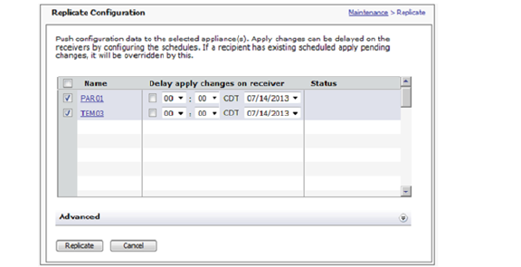
Note: This page may take a long time to display if a configured replicate receiver is unreachable. Because the current time and time zone is retrieved from the receiver, the current time is incorrect and the time zone is not shown.
2. Expand the Advanced section by clicking the  down arrow icon to the right of the Advanced heading.
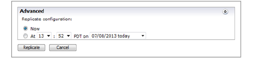
3. To immediately replicate data to the appliances, select Now in the Advanced section.
4. To replicate data to the appliances at a later time, select the time and date from the drop-down lists in the Advanced section.
5. In the list of receiving appliances, select when the replicated data will be applied on each appliance by checking the check box next to an appliance and then selecting the time and date from the drop-down lists in
6. the Delay apply changes on receiver column. The time is based on the local time where the receiving appliance is located.
Each appliance can apply replicated data at a different time, but the time must be later than the replication time specified in the Advanced section.
7. Click Replicate.
Related Topics
: •: Replication Status Messages on page 321
During replication the changing status of each node in the collection is displayed on the Replicate Configuration page. The rate at which replication progresses will differ among the appliances, depending on factors such as network latency. The sending appliance might, for example, be starting replication on one appliance, and already validating it on another.
The following table shows the status messages in roughly the same order they appear during replication.
|
Note•: Replication can fail on one node but continue on all others; in other words, the nodes in the collection are validated and changes are applied independent of what happens on the other destination nodes.
: •: The replication process can be canceled up until the configuration data is applied (before the message in the Status column reads “Applying configuration...”).
Viewing Configuration Data Recipients
In order to receive configuration data, an appliance must first be added as a member of a collection by the “sending” appliance, as described in Defining a Collection of Appliances to Receive Configuration Data on page 316. Regardless of whether the appliance is configured to send or receive configuration data, you can always see a list of the other collection members.
To view collection members on an appliance set up to receive configuration data
On any page in AMC, click the Configuration recipient link in the top, right-hand corner. The appliances in the collection are listed on the Configure Replication page.
To view collection members on an appliance set up to send configuration data
From the main navigation menu in AMC, click Maintenance, and then click the Configure button in the Replicate area.
Note: If there is a high-availability cluster of appliances in the collection, it is treated as one node and referred to by a single name.
Upgrading, Rolling Back, or Resetting the System
Dell SonicWALL periodically offers software updates that add new functionality or address existing issues. An update is delivered as a compressed .bin file and can be in the form of a hotfix or an upgrade:
: •: A hotfix addresses issues with a particular version of the appliance software and typically contains only the files that have changed from the original version.
: •: An upgrade is a new version of the software (the version number on the appliance is incremented).
Installing either kind of update, or rolling back to a previous version, can be done using AMC.
To view the current version of the system, click System Status or Maintenance from the main navigation menu. If any hotfixes have been applied, you can view the list by clicking the hotfixes link.
: •: Updating the System on page 323
: •: Rolling Back to a Previous Version on page 328
: •: Resetting the Appliance on page 328
: •: Performing a Factory Reset on page 693
You can find system updates (hotfixes and upgrades) on the MySonicWALL Web site. To access www.mysonicwall.com, you must first create an account, which is described in Creating a MySonicWALL Account on page 342. Once you have an account, new system updates and documentation are available in the Download Center on the Web site.
: •: Naming Conventions for Upgrades on page 323
: •: Naming Conventions for Hotfixes on page 324
: •: Installing System Updates on page 325
Naming Conventions for Upgrades
Dell SonicWALL uses the following syntax to describe version numbers for upgrade files:
upgrade-<major>.<minor>.<micro>-<build>.bin
The version number for AMC (displayed in the bottom-left corner of every AMC page) and client software follows a similar pattern:
<major>.<minor>-<micro>-<build>
|
To find out if any hotfixes have been applied, click System Status or Maintenance from the main navigation menu.
Related Topics
: •: Naming Conventions for Hotfixes on page 324
: •: Installing System Updates on page 325
Naming Conventions for Hotfixes
Between releases Dell SonicWALL may issue a hotfix that replaces a subset of the software files on your E-Class SRA appliance. Hotfix filenames use the following naming convention:
<component>-hotfix-<version>-<hotfix number>.gz
For example, admin-hotfix-10__x-001.gz is hotfix 001 for version 9.0.0 and later that fixes a problem in Aventail Management Console. The <component> is one of the following:
|
Note: To check whether any hotfixes have been applied, click System Status or Maintenance from the main navigation menu. If any hotfixes have been incorporated, you’ll see a hotfixes link next to the version number. Click the link for more information about which ones have been applied.
Related Topics
: •: Naming Conventions for Upgrades on page 323
: •: Installing System Updates on page 325
You can use AMC to install version upgrades and hotfixes manually or automatically at a scheduled time. For information on updating the software on a cluster, see Upgrading a Cluster on page 544.
Manual System Update
To download and install a system upgrade or hotfix
1. From the main navigation menu in AMC, click Maintenance.
In the System software updates area, click Update.
If you have not already downloaded the upgrade or hotfix file, click the Web site link (login required) and download the appropriate file from www.mysonicwall.com to your local file system.
4. Type the path of the file, or click Browse to locate it.
5. Click Install Update. A file upload status indicator appears. If necessary, you can click Cancel to stop the upload process.
After the file upload process is complete, the update is automatically installed on the appliance. You cannot cancel the installation process. After the installation process is complete, the appliance automatically restarts.
6. After the appliance restarts, log in to AMC and verify the new version number in the bottom-left corner of the AMC home page.
Note: If you see an error message indicating that a upgrade file is invalid or corrupt, follow the steps in Verify a Downloaded Upgrade File on page 697 to see if the checksum for the file is correct.
Scheduled System Update
To schedule software replication:
1. Download the software file from MySonicWALL.com.
2. Under the main navigation menu, click Maintenance and then click the Update... button in the Update section of the Maintenance tab.
a.In the Update page, click the Browse button and select the software to be installed.
b.Expand the Advanced section by clicking the  down arrow icon to the right of the Advanced heading.
3. To replicate the software file at a later time, click the At radio button and select the desired time and date.
You also may apply the pending changes immediately by selecting the Now radio button.
4. Click Install Update to replicate the software update at the selected time.
Related Topics
: •: Naming Conventions for Upgrades on page 323
: •: Naming Conventions for Hotfixes on page 324
: •: Upgrading a Cluster on page 544
Rolling Back to a Previous Version
From AMC, you can undo the most recent update installed on the system. If you experience problems after installing an upgrade or hotfix, you may want to use this feature to roll back to a known state. Each time you roll back, the most recent update is removed.
Caution: If you have made any configuration changes since you updated the appliance they will be lost if you restore a previous version of the system software. When you remove a hotfix, on the other hand, your configuration changes are preserved.
To roll back to a previous version
1. From the main navigation menu in AMC, click Maintenance.
2. In the System configuration area, click Rollback.
3. To roll back to the version displayed on the Rollback page, click OK. After the rollback process is complete, the appliance automatically restarts and applies the changes.
4. After the appliance restarts, verify the new version number in the bottom-left corner of the AMC home page.
Related Topics
: •: Resetting the Appliance on page 328
: •: Performing a Factory Reset on page 693
From AMC, you can reset your appliance using one of three reset levels. The mildest level erases your configuration information, log files, and the current firmware, but leaves you the option to roll back to a previous version, if one is loaded.
The second level removes all configuration, log files, and firmware from the appliance. With this option, you cannot roll back to a previous version.
The third level also removes all configuration, log files, and firmware from the appliance, and then securely erases the hard drive, which can take up to 45 minutes. If you select this option, you cannot roll back to a previous version.
There are a couple of scenarios in which a reset may be appropriate:
: •: You want to completely clean the machine and reuse it elsewhere.
: •: The appliance is in an unrecoverable state. In this case, you should contact Dell SonicWALL Technical Support and confirm that there is no other solution to your problem. A reset should be used only as a last resort to restore the appliance to a working condition.
To configure the appliance after it has been reset, you will need to use the LCD panel or serial console.
1. Back up the configuration data on the appliance. You can do this in AMC (see Exporting the Current Configuration to a Local Machine on page 310), or by using Backup Tool (see Saving Configuration Data on page 690).
2. From the main navigation menu in AMC, click Maintenance.
3. Near the top of the page, click Reset.
4. On the Maintenance > Reset page, select one of the following three radio buttons under Reset Options:
: –: Reset the current configuration – This option erases your current configuration. If you upgraded from a previous version, selecting this option retains the ability to roll back.
: –: Reset the entire appliance – This option erases your configuration and deletes all firmware versions on the appliance. If you select this option, you cannot roll back to a previous version.
: –: Securely erase the hard drive and reset the entire appliance – This option erases your configuration, deletes all firmware versions, and securely erases the hard drive. If you select this option, you cannot roll back to a previous version.
Note: Securely erasing the hard drive can take up to 45 minutes.
5. At the bottom of the page, click Reset to proceed with the reset. To cancel the reset, click Cancel.
Related Topics
: •: Performing a Factory Reset on page 693
: •: Exporting the Current Configuration to a Local Machine on page 310
The Scheduler tab on the Maintenance page, which lists all scheduled activities, can be used to delete, reschedule, or immediately execute scheduled tasks:
: •: Apply Pending Changes
: •: Replication
: •: Install Updates and Hotfixes
Note: Scheduled activities are also displayed in the audit and management logs.
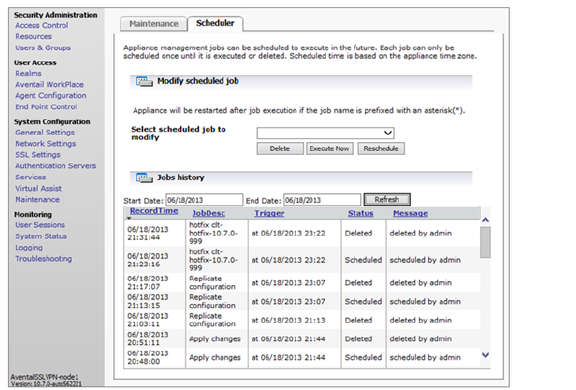
Use the Start Date and End Date fields to display only activities created or modified with a specific date range. Activities can also be sorted in ascending or descending order based on the content of any column.
To delete an activity, select the activity and click the Delete button.
To execute an activity immediately, select the activity and click the Execute Now button.
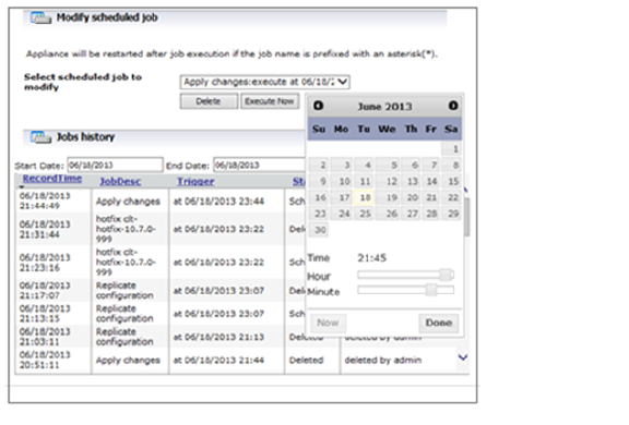
To reschedule an activity, select the activity and click the Reschedule button. When the calendar appears, select the date when data will be replicated, use the Hour and Minute sliders to select the time in 5-minute increments, and then click Done.
Encryption is used to ensure data security for all traffic on the appliance. The appliance encrypts all data using SSL. You must configure at least one cipher to be used with SSL to secure your network traffic. Select the “best” cipher from the available set, balancing security and performance trade-offs (security is weighted much more heavily than performance).
SSL provides some degree of protection from downgrade attacks, but in general you should configure your servers to permit only those ciphers that you consider strong enough for your needs. The cipher order, from most to least preferred, is:
: •: AES 256-bit, with SHA-256
: •: AES 128-bit, with SHA-256
: •: AES 256-bit, with SHA-1
: •: AES 128-bit, with SHA-1
: •: Triple DES, with SHA-1
: •: RC4 128-bit, with SHA-1
: •: RC4 128-bit, with MD5
Related Topics
: •: Configuring SSL Encryption on page 332
The appliance uses SSL encryption and other cryptographic algorithms—or ciphers—to secure data transfer. When configuring the encryption settings for the appliance, you must enable at least one cipher to be used in conjunction with SSL to secure your network traffic. The default settings are typically sufficient for most deployments.
To configure SSL encryption settings
1. From the main navigation menu, click SSL Settings, and then click the Edit link in the SSL Encryption area. The Configure SSL Encryption page appears.
Check the Use only government-recommended encryption check box to enable FIPS 140-2 compliant encryption settings. This configures the appliance to use only the TLS protocol and enables only FIPS-compliant ciphers.
This option is often used to disable TLS 1.1 and 1.2 and the corresponding certificate notifications when SSL and CA certificates haven’t been upgraded from TLS 1.0.
3. To enable FIPS 140-2 compliant encryption, check the transport protocols used to encrypt traffic. This configures the appliance to use only the TLS protocol and enables only FIPS-compliant ciphers.
4. Select the version of TLS transport protocol that the appliance will use.
5. Select the ciphers that the access services (Web proxy, network proxy, and network tunnel) on the appliance will accept for SSL connections.
6. To compress encrypted SSL data using LXS compression, check the Enable cipher compression check box.
7. In the SSL handshake timeout box, type the number of seconds that an SSL handshake can last before timing out. The default is 300.
8. Click Save.
This section describes configuring your E-Class SRA appliance to use FIPS mode.
FIPS (Federal Information Processing Standard) 140-2 Level 2 is a validation standard for evaluating cryptographic modules, and includes stringent reviews of source code, algorithms, physical security, and operational testing on cryptographic security products. The United States Federal Government is required to purchase cryptographic products validated to the FIPS 140-2 standard. In the international marketplace, ISO19790 is being adopted as a standard and is a direct adaptation of FIPS 140-2.
The E-Class SRA E-Class SRA EX9000, EX7000, and EX6000 appliances have FIPS 140-2 Level 2 certification from NIST (the National Institute of Standards and Technology, the United States FIPS 140-2 Cryptographic Module Validation Authority) and CSE (the Communications Security Establishment, the Canadian FIPS 140-2 Cryptographic Module Authority).
Note: FIPS is supported only from 10.7.1 onwards. Version 10.7.0 is not FIPS certified.
FIPS mode is transparent to end users. Internally, FIPS mode enforces secure communication and system integrity.
: •: Requirements for FIPS on page 333
: •: Enabling FIPS on page 335
: •: FIPS Violations on page 335
: •: Disabling FIPS on page 337
The following items are required to properly configure FIPS for full compliance:
: •: A EX9000, EX7000, or EX6000 appliance. No other appliances are FIPS-certified.
Caution: If you have purchased an E-Class SRA E-Class SRA EX9000, EX7000, or EX6000 appliance with 140-2 Level 2 FIPS certification, the tamper-evident sticker affixed to it must remain in place.
: •: A license to run FIPS
: •: A secure connection to your authentication server
: •: A strong administrator password, which should be at least 14 characters long and contain punctuation characters, numbers, and a combination of uppercase and lowercase letters. In addition, you must specify an authentication server when you set up a realm; "null auth" is not allowed.
: •: When in FIPS mode, the Grub shell MUST be disabled in order to prevent a user from gaining unauthorized access to its shell.
Caution: Modification of any Grub configuration files IS NOT allowed. Modification makes the device Non-FIPS compliant and causes the device to become inoperable.
The following states prevent FIPS from being activated, or from reaching full compliance:
: •: Unsecured connections with authentication servers
: •: Use of RADIUS authentication servers
: •: Use of LDAP authentication servers without using SSL connections employing only FIPS approved ciphers
: •: Use of Active Directory single domain authentication servers without using SSL connections employing only FIPS approved ciphers
: •: Use of RSA ClearTrust authentication servers without using SSL connections employing only FIPS approved ciphers
: •: Use of RSA Authentication Manager authentication servers without strong passwords as shared secrets
: •: Use of USB devices for any purpose
: •: Use of clustering (High Availability)
Clustering (HA) is not supported in FIPS mode.
: •: Use of Dell SonicWALL GMS or Viewpoint servers
: •: Loading or unloading of any kernel modules via the shell command line
: •: Installation of third party software via the shell command line
: •: Firmware upgrades via the shell command line
: •: Use of Debug 1, Debug 2, Debug 3 or plaintext logging
: •: Use of certificates with private/public key-pairs generated by a non-FIPS-compliant system
: •: Use of the zeroization procedure without the primary administrator being physically present until the procedure completes
FIPS mode is not automatically enabled after you import your license. You must set it up as described in Enabling FIPS on page 335.
Managing FIPS-Compliant Certificates
Any keys generated on an EX9000, EX7000, or EX6000 appliance running in FIPS mode will be FIPS compliant. If you import certificates (and their associated public and private keys) to the appliance, it is your responsibility to make sure that they are also FIPS compliant. Certificates must be exported and then reimported when you switch FIPS mode on or off. For the export and import procedure, see Exporting and Importing FIPS-Compliant Certificates on page 336.
The best way to ensure that the certificates you’re using are FIPS compliant is to generate all CSRs (certificate signing requests) on a FIPS-enabled appliance.
: •: Exporting and Importing FIPS-Compliant Certificates on page 336
Your appliance validates its integrity several ways:
: •: A self test is performed at each power-on cycle to verify all FIPS approved cryptographic algorithms are functioning properly. If any of the self tests fail, the Alarm LED on the front panel will remain lit, a message detailing the specific failure will be displayed on the serial console and logged in /var/log/aventail/fips.log, and the appliance will be halted. You should power-cycle the appliance once to see if it recovers. If it does not, you will need to contact Dell SonicWALL customer support for further instructions.
: •: A continuous self test is performed on the random number generator and on the generation of new Certificate keys to verify the integrity of cryptographic operations. If any of these self tests fail, a message detailing the specific failure will be displayed on the serial console and logged in /var/log/aventail/fips.log, and the appliance will be immediately power-cycled via a reboot in order to perform the rigorous self-tests for system integrity.
: •: All critical security binaries are signed and hashed. Alterations to any of these binaries will be detected at each reboot and immediately on a running system. If this occurs during the power-cycle self tests, the Alarm LED on the front panel will remain lit, a message detailing the specific tampering will be displayed on the serial console and logged in /var/log/aventail/fips.log, the system will be halted and you will need to contact Dell SonicWALL customer support for further instructions. If this tampering is detected on a running system, the appliance will be immediately power-cycled via a reboot in order to perform the rigorous self-tests for system integrity.
: •: All critical security configuration files are signed and hashed. Manual alterations (as opposed to alterations made using the AMC) to any of the configuration files will cause the appliance to immediately transition into an error state. If this tampering is detected on a running system, the appliance will be immediately power-cycled via a reboot in order to perform the rigorous self-tests for system integrity. Otherwise, if it is detected during power-cycle self-tests, a message detailing the specific tampering will be displayed on the serial console and logged in /var/log/aventail/fips.log, the Test LED on the front panel remain lit and the system will be placed in single user mode with networking disabled. The primary administrator will need to log in via the serial console and restore tampered configuration files with valid backup copies or perform a configuration reset prior to power-cycling the appliance.
: •: Firmware upgrade files are signed and hashed. If an upgrade file fails its integrity check, the upgrade process is aborted without making any state changes to the appliance, a message detailing the failure is displayed on the AMC Web page, and the appliance remains fully functional.
Before you enable FIPS mode, you must have a strong password, a secure connection to your authentication server, and a valid license.
Obtain your FIPS license as described in Software Licenses on page 338.
To be FIPS-compliant, your password must be at least 8 characters long, but it is recommended that you use at least 14 characters. Although this requirement is not enforced by the software, having a weak administrator password leaves you vulnerable. A strong password includes a mix of letters, numbers and symbols. Think of this as a phrase, not just a password. For instance, “I never saw @ purple cow, I never hope 2C1.” has a combination of all three types of characters.
Only administrators with System rights can change the FIPS mode. When in FIPS mode, you will not be able to select non-compliant SSL algorithms.
To use your existing, FIPS-compliant certificates while in FIPS mode, export the certificates before enabling FIPS and then import them again after FIPS is enabled. See Exporting and Importing FIPS-Compliant Certificates on page 336.
To enable FIPS
1. In the main navigation menu, click General Settings, then click FIPS Security.
2. Click Edit.
3. If you have imported your license, select the Enable FIPS mode check box.
Note: Existing certificates will be deleted from the system in the next step. To preserve your FIPS-compliant certificates, ensure that you have exported them.
4. Click Save and then apply your Pending changes.
Caution: Once in FIPS mode, you cannot edit system configuration files.
If your appliance configuration is not FIPS-compliant, in the upper-right corner you will see an alert link that says FIPS-compliance warning. Click on the link for more information on how to bring your appliance configuration into FIPS-compliance.
Caution: The lack of this alert does not mean your environment is FIPS compliant. It is your responsibility to ensure all FIPS prerequisites are met in order to be FIPS compliant.
: •: Exporting and Importing FIPS-Compliant Certificates on page 336
: •: Disabling FIPS on page 337
Exporting and Importing FIPS-Compliant Certificates
If you know your existing Certificate keys were generated on a FIPS-compliant system and you want to use them after FIPS is enabled, you must export them before enabling FIPS and then import them after FIPS is enabled.
Similarly, if you plan to disable FIPS mode on your system and you want to use your FIPS-compliant certificates after disabling FIPS, you must export them before disabling FIPS and then import them after FIPS is disabled.
To export Certificates before the FIPS-mode transition:
1. In AMC, navigate to SSL Setting > SSL Certificates.
2. For each certificate to export, do the following:
a.On the Certificates table, select a certificate and click the Export button.
b.Enter a password for encrypting the exported .p12 file.
c.Click the Save button
To import certificates after the FIPS-mode transition:
1. In AMC, navigate to SSL Settings > SSL Certificates.
2. For each certificate to import, do the following:
a.On the Certificates table, select New > Import certificate....
b.Select the certificate file to import.
c.Enter the password with which the .p12 file was encrypted.
d.Click the Import button
Turning off FIPS disables the FIPS feature and removes all constraints imposed by the FIPS mode prerequisites.
Caution: Warning: To be fully FIPS compliant, no FIPS critical security parameters can be used outside of the FIPS approved mode of operation. A few of these parameters are burned into the firmware itself and thus to be fully compliant, zeroization must be performed. If you wish to continue using your system rather than returning the hardware to Dell SonicWALL for zeroization, and you are willing to knowingly skip zeroization, you can disable FIPS mode in the AMC. This will logically destroy all configurable parameters.
To use your existing, FIPS-compliant certificates after disabling FIPS mode, export the certificates before disabling FIPS and then import them again after FIPS is disabled. See Exporting and Importing FIPS-Compliant Certificates on page 336.
To disable FIPS
1. From the main navigation menu, click General Settings, then click FIPS Security.
2. Click Edit.
3. Clear the box next to Enable FIPS mode.
Note: Existing certificates will be deleted from the system in the next step. To preserve your FIPS-compliant certificates, ensure that you have exported them.
4. Click Save and then apply your Pending changes.
Caution: Your appliance will be rebooted to apply these changes. Any connections will be terminated.
: •: Exporting and Importing FIPS-Compliant Certificates on page 336
Zeroization is the practice of permanently destroying all critical security parameters. This is accomplished by overwriting the entire disk with zeros. Zeroization makes it very hard to retrieve sensitive data from the appliance. It is used before recycling hardware, or in other cases where data security is more important than retaining the data. Once this operation is completed, the appliance can no longer be used at your site and must be returned to Dell SonicWALL for replacement hardware to restore service.
To Zeroize the appliance:
1. Select Maintenance from the main navigation pane of the management console.
2. Select Reset.
3. On the Reset page, select the type of reset you want to perform as explained in To reset the appliance on page 328.
4. Once the reset begins, stay physically present with the appliance until the appliance halts.
Caution: Your appliance can take up to 45 minutes to complete the zeroization process.
This section describes how to manage software licenses for appliance components. The E-Class SRA appliance uses different types of licenses:
: •: Administration test license: When you receive your E-Class SRA appliance, you must log in to MySonicWALL to retrieve your initial user license, which is valid for one user (the administrator plus one end user) for an unlimited number of days. This allows you to become familiar with the AMC, which you will use to upload an appliance license file for additional users or other components.
: •: Appliance licenses: This license is used to monitor and enforce concurrent user counts. If you exceed your concurrent active user limit, user access is restricted until the active user count drops below the licensed user limit.
The E-Class SRA appliance supports the following:
: –: Up to 20,000 concurrent users on an EX9000 appliance
: –: Up to 5,000 concurrent users on an EX7000
Depending on your licensing arrangements, however, you may be allowed to exceed the limit by a certain number of user sessions. In this case, user access is still allowed but the excess usage is logged. If the active user count exceeds the grace count, however, user access is restricted until the active user count drops below the grace count.
If user access is restricted, users attempting to log in to your VPN see an error message indicating that the license count may have been exceeded, and they are denied access to your network.
: •: Component licenses: If the license for an appliance component (such as OnDemand) has expired, users attempting to use that component see an error message in Aventail WorkPlace. In the case of a Spike License, the number of days remaining on it and how many users are covered by it are displayed in AMC.
All license files must be retrieved from www.mysonicwall.com and imported to the appliance, as described in Managing Licenses on page 341.
: •: How Licenses Are Calculated on page 339
: •: Viewing License Details on page 339
: •: Managing Licenses on page 341
A user license for the appliance does not represent a person, but rather a user authentication. If a user logs in to WorkPlace on a desktop computer, for example, and is also logged in on a mobile device, two licenses are consumed as soon as the user accesses a resource that’s protected by the appliance.
A license is released when a connection has been inactive for 15 minutes. How this inactivity is measured depends on the user’s access method:
: •: With translated, custom port mapped, or custom FQDN mapped Web access, the license is released after 15 minutes during which no resources are accessed.
: •: When Connect Tunnel is running, the connection to the appliance is kept open, which means that the license is in use as long as the tunnel is up. Once the tunnel is disconnected, the license is released after 15 minutes.
There are a few ways to restrict or end sessions:
: •: Restrict the number of licenses that a person can have on a per-community basis. When the limit is reached, no further appliance sessions (and no access to resources) are allowed. The user can start a new session only by terminating all existing sessions. For a description of the Maximum active sessions setting, see Assigning Members to a Community on page 66.
: •: Have tunnel client sessions terminate—on a per-community basis—when the time period set for Credential lifetime (on the Configure General Appliance Options page) is reached. For a description of the Limit session length to credential lifetime setting, see Ending User Sessions on page 294.
: •: Terminate a user session manually. See Viewing User Sessions on page 290 for information on how to end user sessions in AMC. Also see Open vs. Licensed Sessions on page 293 for more on the distinction between different types of sessions.
Note: Users who reach the limit of their appliance licenses and then attempt to authenticate with just a client certificate are not prompted to terminate all existing sessions. These users must terminate an existing session in order to free up a license and start a new one. The best method for terminating a session is for the user to log out, otherwise he or she must wait 15 minutes for the session to time out and a license to be released.
In AMC, you can view the status of your base appliance license and the licenses for any other appliance components you may have purchased, such as OnDemand or Spike License. This section describes how to view details about the status of your licenses.
To view license details
1. From the main navigation menu, click General Settings, and then click the Edit link in the Licensing area. The Manage Licenses page appears.
Review the information provided:
|
This section describes how to obtain your appliance licenses from www.mysonicwall.com. You must have a base appliance license file if, for example, you want to replace an evaluation license with a permanent license after deciding to purchase an appliance. There are also some components—such as Connect and Spike License—that require a separate purchase and license.
Before you can enable your appliance or a component that requires a separate purchase and license, you must follow these steps:
1. Create a MySonicWALL account, if you don't already have one. You need an account in order to register your appliance. (MySonicWALL registration information is not sold or shared with any other company.) See Creating a MySonicWALL Account on page 342 for more information.
2. Register your device on MySonicWALL. Registration provides access to essential resources, such as your license file, firmware updates, and technical support information. See Registering Your E-Class SRA E-Class Appliance on page 342 for more information.
3. Use your mySonicWALL account to apply the license for your appliance. If you have a high-availability cluster, you must apply a separate license to each appliance. See Retrieving Your E-Class SRA E-Class License on page 343 for more information.
4. Apply your license file in AMC; see Applying Your E-Class License on page 343 for more information.
Caution: You should ensure that the appliance’s date and time settings are configured correctly for your time zone before importing a license file. For information about configuring the system clock settings, see Configuring Time Settings on page 275.
: •: Creating a MySonicWALL Account on page 342
: •: Registering Your E-Class SRA E-Class Appliance on page 342
: •: Retrieving Your E-Class SRA E-Class License on page 343
: •: Applying Your E-Class License on page 343
: •: Managing a Spike License on page 344
Creating a MySonicWALL Account
To create a MySonicWALL account, complete the short online registration form. Registration information is not sold or shared with any other company.
To create a mySonicWALL account
1. In your Web browser, go to the following Web site:
https://www.mysonicwall.com/
2. In the User Login section, follow the link for unregistered users.
3. Enter your account information, personal information, and preferences, and then click Submit. Be sure to use a valid email address.
4. Follow the prompts to finish creating your account. Dell SonicWALL will send a subscription code to the email address you entered in step 3.
5. When you return to the login screen, log in with your new username and password.
6. Confirm your account by entering the subscription code you received in email.
Related Topics
: •: Registering Your E-Class SRA E-Class Appliance on page 342
Registering Your E-Class SRA E-Class Appliance
Registration provides access to essential resources, such as your license file, firmware updates, documentation, and technical support information.
To log in to your MySonicWALL account and register your appliance
2. Locate your software Serial Number, which is printed on the back of your E-Class SRA E-Class appliance.
3. Enter your serial number, and then click Next. Follow the on-screen instructions.
4. Confirm your Serial Number.
5. Enter a name for this appliance.
6. Enter the authentication code for this appliance, which is the hardware identifier for the appliance you purchased. The authentication code is displayed in AMC: click General Settings from the main navigation menu, and then look in the Licensing area.
7. Click Register to continue.
Follow the online prompts to fill out the survey and complete the registration process.
: •: Retrieving Your E-Class SRA E-Class License on page 343
Retrieving Your E-Class SRA E-Class License
To retrieve the license file for your appliance, log in to your MySonicWALL account. If you have a high-availability cluster, you must download a separate license for each appliance.
To retrieve the license file for your appliance
2. Click the link for the appliance that requires a license.
3. On the Service Management page, select the appliance software version from the drop-down list for the license you are retrieving.
4. Click the link for the license file (.xml) and save it to your computer. After you get your appliance up and running you must import this license file using AMC.
Related Topics
: •: Applying Your E-Class License on page 343
The E-Class SRA appliance ships with a single administration test license that supports 1 user indefinitely; to test or deploy the appliance with additional users, or to enable separate components, such as a Spike License, you must apply a valid license file. Log in to your MySonicWALL account, retrieve the license file, and import it in AMC.
To retrieve the license file from MySonicWALL and import it
2. Click the link for the appliance that requires a license.
3. On the Service Management page, select the appliance software version from the drop-down list for the license you are retrieving.
4. Click the link for the license file (.xml) and save it to your computer.
5. From the main navigation menu in AMC, click General Settings, and then click the Edit link in the Licensing area. The Manage Licenses page appears.
6. Click Import License.
In the License file box, type the path for the license file, or click Browse to locate it.
8. Click Upload, and then apply the change by clicking the Pending changes link in the upper-right corner.
A Spike License enables you to temporarily increase the number of remote users you can support in the event of a disaster or other business disruption. Licensed separately, this feature helps you accommodate spikes in remote access traffic during planned or unplanned events.
When you buy a Spike License it is valid for a given number of users and days (this is the total number of users who are supported when the Spike License is activated, not in addition to your base license number). You can suspend and resume the use of the license as needed.
Activating, pausing, and resuming a Spike License
1. Retrieve your Spike License from mySonicWALL and import it to the appliance, as described in Applying Your E-Class License on page 343.
2. The Spike License is listed as Available on the Manage Licenses page in AMC. When you need to accommodate more users, click Activate. The maximum number of possible users is updated, and the timeline for your Spike License is displayed.

3. Click Pause to suspend use of the Spike License, and click Resume to continue using it.
Note•: You can upload more than one Spike License to your appliance, but you cannot have more than one active at a time.
: •: Whenever you activate or pause a Spike License, the number of days for which it is valid decreases by one, even if fewer than 24 hours have elapsed.