|
1
|
Click the Settings tab.
|
|
2
|
|
3
|
Click the External Collector tab.
|
|
4
|
In External Collector Settings, select the Send AppFlow and Real-Time Data To External Collector checkbox.
|
|
5
|
|
6
|
Specify the External Collector’s IP address in the provided field.
|
|
7
|
Optionally, for the Source IP to Use for Collector on a VPN Tunnel, specify the source IP if the external collector must be reached by a VPN tunnel.
|
|
8
|
|
9
|
Click the Accept button at the top of the page.
|
|
1
|
Click the External Collector tab.
|
|
2
|
In External Collector Settings, select the Send AppFlow and Real-Time Data To External Collector checkbox.
|
|
3
|
|
4
|
Specify the External Collector’s IP address in the provided field.
|
|
5
|
Optionally, for the Source IP to Use for Collector on a VPN Tunnel, specify the source IP if the external collector must be reached by a VPN tunnel.
|
|
6
|
|
7
|
Click the Settings tab.
|
|
8
|
|
•
|
Interface-based: when enabled, the flows reported are based on the initiator or responder interface.
|
|
•
|
Firewall/App Rules-based: once enabled, the flows reported are based on already existing firewall rules.
|
|
9
|
Click the External Collector tab.
|
|
10
|
IPFIX uses templates that must be known to an external collector before sending data. In Actions, click the Generate ALL Templates button to begin generating templates. A message requesting confirmation displays.
|
![]()
|
11
|
To begin generating static flow data, click the Generate Static AppFlow Data button. A message requesting confirmation displays.
|
![]()
|
1
|
Click the External Collector tab.
|
|
2
|
In External Collector Settings, select the Send AppFlow and Real-Time Data To External Collector checkbox.
|
|
3
|
|
4
|
Specify the External Collector’s IP address in the provided field.
|
|
5
|
For the Source IP to Use for Collector on a VPN Tunnel, specify the source IP if the external collector must be reached by a VPN tunnel.
|
|
6
|
|
7
|
Click the Settings tab.
|
|
8
|
|
•
|
Interface-based: when enabled, the flows reported are based on the initiator or responder interface.
|
|
•
|
Firewall/App Rules-based: when enabled, the flows reported are based on already existing firewall rules.
|
|
9
|
Click the External Collector tab.
|
|
10
|
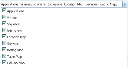
Select the tables you wish to receive static flows for from the Send Static AppFlow For Following Tables drop-down menu.
|
|
11
|
Select the tables you wish to receive dynamic flows for from the Send Dynamic AppFlow For Following Tables drop-down menu.
|
|
12
|
Select any additional reports to be generated to a flow from the Include Following Additional Reports via IPFIX drop-down menu.
|
|
13
|
At the bottom of the page, click the Generate ALL Templates button to begin generating templates.
|
|
14
|
Enable the option to Send static flows at regular intervals by selecting the checkbox. After enabling this option, click the Generate Static Flows button.
|
![]()
|
15
|
To begin generating static flow data, click the Generate Static AppFlow Data button. A message requesting confirmation displays.
|
![]()
|
16
|
Click Accept.
|
|
1
|
Click the Settings tab.
|
|
2
|
|
3
|
Click the External Collector tab.
|
|
4
|
Click the Send Flows and Real-Time Data To External Collector checkbox.
|
|
5
|
Select IPFIX with extensions or IPFIX with extensions v2 from the External Flow Reporting Format drop-down menu.
|
|
6
|
Specify the External Collector’s IP address in the provided field.
|
|
7
|
If the external collector must be reached by a VPN tunnel, specify the source IP in the Source IP to Use for Collector on a VPN Tunnel field.
|
|
8
|
|
9
|
Click the Send Static AppFlow At Regular Interval checkbox.
|
|
10
|
Select the tables you wish to receive static flows for from the Send Dynamic AppFlow For Following Tables drop-down menu.
|
|
11
|
Click the Generate Static AppFlow Data button.
|
|
12
|
Click Accept.
|
|
13
|
Next, navigate to the Network > Interfaces screen.
|
|
14
|
Confirm that Flow Reporting is enabled per interface by clicking the Configure icon of the interface you are requesting data from.
|
|
15
|
|
16
|
Click OK.
|