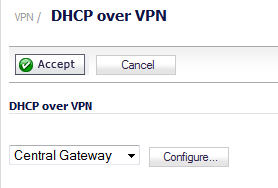
In this example, the central IPsec gateway acts as the SonicPoint WLAN controller; see SonicPoint Layer 3 Management over IPsec Configuration. The SonicPoint is deployed under the VPN local LAN subnet of the remote IPsec gateway. SonicPoint clients receive a DHCP client lease for the SonicPoint from the DHCP scope on the central gateway. The DHCP over VPN feature must be configured on the remote IPsec gateway.
SonicPoint Layer 3 Management over IPsec Configuration
To configure SonicPoint Layer 3 Management over IPsec, perform the following steps:
|
1
|
Navigate to the VPN > Settings page.
|

|
2
|

|
3
|
|
4
|
From the Authentication Method drop-down menu, select the method you want. For example, IKE using Preshared Secret. This is the default.
|
|
5
|
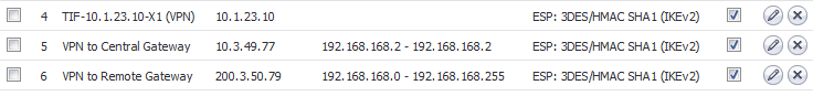
In the Name field, enter a descriptive name for the VPN tunnel. For example, VPN to Central Gateway.
|
|
6
|
In the IPSec Primary Gateway Name or Address field, enter the IP address of the remote gateway. For example, 10.03.49.77.
|
|
8
|
Click the Network tab.
|

|
9
|
|
10
|
|
11
|
Under Remote Networks, select the option you want and, if applicable, the network you want from the associate drop-down menu.
|
|
12
|
Click the Advanced tab.
|

|
13
|
Select the Allow SonicPoint N Layer 3 Management option.
|
|
14
|

|
15
|
|
16
|
|
17
|
|
19
|
Click OK.
|
|
1
|
Navigate to the VPN > Settings page.
|
|
2
|
|
3
|
|
4
|
From the Authentication Method drop-down menu, select the appropriate method for your network. For example, IKE using Preshared Secret. This is the default.
|
|
5
|
|
6
|
In the IPSec Primary Gateway Name or Address field, enter the IP address of the remote gateway. For example, 10.03.49.79.
|
|
7
|
Click the Network tab.
|

|
8
|
|
9
|
|
10
|
Under Remote Networks, select the option you want and, if appropriate, the network from the associated drop-down menu. The default is Choose destination network from list.
|
|
NOTE: If you have not created an address object for your remote gateway, you can do so by selecting Create new address object from one of the menus.
|
|
11
|
Under Remote Networks, select Create new address object from the appropriate menu. The Add Address Object dialog displays.
|

|
12
|
|
13
|
|
14
|
|
15
|
|
16
|
|
17
|
Click OK.
|
|
18
|
Click the Advanced tab.
|

|
19
|
Select the Allow SonicPointN Layer 3 Management option.
|
|
20
|
|
21
|
|
22
|
|
23
|

|
24
|
From the DHCP lease bound to drop-down menu, select the interface that is connected to the SonicPoint. For example, Interface X4.
|
|
25
|
(Optional) Select the Accept DHCP Request from bridged WLAN interface option if you want it.
|
|
26
|
In the Relay IP Address field, enter the IP address of the interface connected to the SonicPoint. For example 30.30.30.1.
|
|
27
|
In the Remote Management IP Address field, enter the IP address that is used to manage this SonicWall security appliance remotely from behind the Central Gateway.
|
|
NOTE: This IP address was configured in Configuring the Access Controller Interface, and must be reserved in the DHCP scope on the DHCP server. In the example it is 10.10.10.1.
|
|
28
|
Select the Block traffic through tunnel when IP spoof detected option.
|
|
29
|
Select the Obtain temporary lease from local DHCP server if tunnel is down option.
|
|
30
|
|
31
|
Click OK.
|
|
1
|
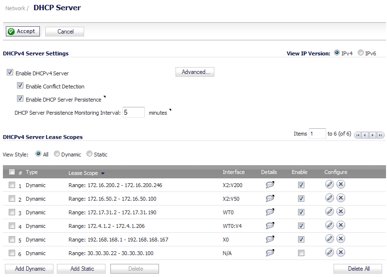
Navigate to the Network > DHCP Server page.
|

|
2
|

|
3
|

|
4
|
|
5
|
|
6
|
In the Option Value field, enter the IP address you want to use for the DHCP group. For example, 192.168.168.168.
|
|
7
|
Click OK to add the DHCP Option Object.
|
|
8
|
|
1
|
Navigate to the Network > DHCP Server page.
|
|
2
|
|
3
|
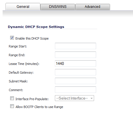
Select the Enable this DHCP Scope option. This is the default.
|
|
4
|
In the Range Start field, enter the IP address at which to start the DHCP range. For example, 30.30.30.2.
|
|
NOTE: The range values must be within the same subnet as the Default Gateway. For example, 30.30.30.2 to 30.30.30.100.
|
|
5
|
In the Range End field, enter the IP address at which to end the DHCP range. For example, 30.30.30.100.
|
|
6
|
|
7
|
In the Default Gateway field, enter the IP address of the default gateway.
|
|
8
|
|
9
|
Click the Advanced tab.
|

|
10
|
In the DHCP Generic Options section, from the DHCP Generic Option Group drop-down menu, select the CAPWAP DHCP option.
|
|
11
|
Select the Send Generic options always option. This is the default.
|
|
12
|

|
1
|
Navigate to the Network > Interfaces page.
|
|
2
|
From the Add Interface drop-down menu in the Interface Settings section, select Add WLAN Tunnel Interface. The Add WLAN Tunnel Interface dialog is displayed.
|

|
3
|

|
4
|
|
5
|
|
6
|
|
7
|
|
8
|
|
9
|
From the SonicPoint Limit drop-down menu, select the maximum number of SonicPoints allowed on your network. For example, 48 SonicPoints. The default is 64 SonicPoints.
|
|
10
|
Optionally, enter a comment in the Comment field.
|
|
11
|
