High Availability : High Availability

Active/Active Clustering Overview
This section provides an introduction to the Active/Active Clustering feature. With Active/Active Clustering, you can assign certain traffic flows to each node in the cluster, providing load sharing in addition to redundancy, and supporting a much higher throughput without a single point of failure.
A typical recommended setup includes four firewalls of the same SonicWALL model configured as two Cluster Nodes, where each node consists of one Stateful HA pair. For larger deployments, the cluster can include eight firewalls, configured as four Cluster Nodes (or HA pairs). Within each Cluster Node, Stateful HA keeps the dynamic state synchronized for seamless failover with zero loss of data on a single point of failure. Stateful HA is not required, but is highly recommended for best performance during failover.
Load sharing is accomplished by configuring different Cluster Nodes as different gateways in your network. Typically this is handled by another device downstream (closer to the LAN devices) from the Active/Active Cluster, such as a DHCP server or a router.
A Cluster Node can also be a single firewall, allowing an Active/Active cluster setup to be built using two firewalls. In case of a fault condition on one of the firewalls in this deployment, the failover is not stateful since neither firewall in the Cluster Node has an HA Secondary.
Redundancy is achieved at several levels with Active/Active Clustering:
Topics:
Example: Active/Active Clustering – Four-Unit Deployment
This diagram shows a four-unit cluster. Each Cluster Node contains one HA pair. The designated HA ports of all four appliances are connected to a Layer 2 switch. These ports are used for Cluster Node management and monitoring state messages sent over SVRRP, and for configuration synchronization. The two units in each HA pair are also connected to each other using another interface (shown as the “Xn” interface). This is the Active/Active DPI Interface necessary for Active/Active DPI. With Active/Active DPI enabled, certain packets are offloaded to the standby unit of the HA pair for DPI processing.
Figure 34. Active/Active four-unit cluster
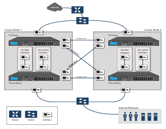
For more information about physically connecting redundant ports and redundant switches, see the Active/Active Clustering Full Mesh Deployment Technote.
Example: Active/Active Clustering – Two-Unit Deployment
This diagram shows a two-unit cluster. In a two-unit cluster, HA pairs are not used. Instead, each Cluster Node contains a single appliance. The designated HA ports on the two appliances are connected directly to each other using a cross-over cable. The SonicWALL Virtual Router Redundancy Protocol (SVRRP) uses this HA port connection to send Cluster Node management and monitoring state messages. SVRRP management messages are initiated on the Master Node, and monitoring information is communicated from every appliance in the cluster. The HA port connection is also used for configuration synchronization between Cluster Nodes.
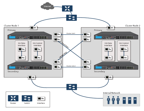
Figure 35. Active/Active two-unit cluster
Benefits of Active/Active Clustering
The benefits of Active/Active Clustering include the following:
How Does Active/Active Clustering Work?
There are several important concepts that are introduced for Active/Active Clustering. See the following sections for descriptions of these new concepts and changes to existing functionality:
About Cluster Nodes
An Active/Active Cluster is formed by a collection of Cluster Nodes. A Cluster Node can consist of a Stateful HA pair, a Stateless HA pair or a single standalone unit. Dynamic state synchronization is only available in a Cluster Node if it is a Stateful HA pair. The traditional SonicWALL High Availability protocol or Stateful HA protocol is used for communication within the Cluster Node, between the units in the HA pair.
When a Cluster Node is a Stateful HA pair, Active/Active DPI can be enabled within the Cluster Node for higher performance.
About the Cluster
All devices in the Cluster must be of same product model and be running the same firmware version.
Within the cluster, all units are connected and communicating with each other. For communication between Cluster Nodes, a new protocol called SonicWALL Virtual Router Redundancy Protocol (SVRRP) is used. Cluster Node management and monitoring state messages are sent using SVRRP.
All Cluster Nodes share the same configuration, which is synchronized by the Master Node. The Master Node is also responsible for synchronizing firmware to the other nodes in the cluster. The HA port connection is used to synchronize configuration and firmware updates.
Dynamic state is not synchronized across Cluster Nodes, but only within a Cluster Node. When a Cluster Node contains an HA pair, Stateful HA can be enabled within that Cluster Node, with the advantages of dynamic state synchronization and stateful failover as needed. In the event of the failure of an entire Cluster Node, the failover will be stateless. This means that pre-existing network connections must be rebuilt. For example, Telnet and FTP sessions must be re-established and VPN tunnels must be renegotiated.
The About Failover provides more information about how failover works.
The maximum number of Cluster Nodes in a cluster is currently limited to four. If each Cluster Node is an HA pair, the cluster will include eight firewalls.
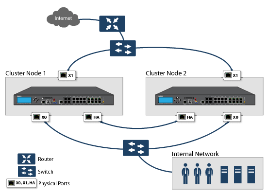
Figure 36. Active/Active two node cluster
Actions Allowed Within the Cluster
The types of administrative actions that are allowed differ based on the state of the firewall in the cluster. All actions are allowed for admin users with appropriate privileges on the active firewall of the Master Node, including all configuration actions. A subset of actions are allowed on the active firewall of Non-Master nodes, and even fewer actions are allowed on firewalls in the standby state. Table 86 lists the allowed actions for active firewalls of Non-Master nodes and standby firewalls in the cluster.
 
About Virtual Groups
Active/Active Clustering also supports the concept of Virtual Groups. Currently, a maximum of four Virtual Groups are supported.
A Virtual Group is a collection of virtual IP addresses for all the configured interfaces in the cluster configuration (unused/unassigned interfaces do not have virtual IP addresses). When Active/Active Clustering is enabled for the first time, the configured IP addresses for the interfaces on that firewall are converted to virtual IP addresses for Virtual Group 1. Thus, Virtual Group 1 will include virtual IP addresses for X0, X1, and any other interfaces which are configured and assigned to a zone.
A Virtual Group can also be thought of as a logical group of traffic flows within a failover context, in that the logical group of traffic flows can failover from one node to another depending upon the fault conditions encountered. Each Virtual Group has one Cluster Node acting as the owner and one or more Cluster Nodes acting as standby. A Virtual Group is only owned by one Cluster Node at a time, and that node becomes the owner of all the virtual IP addresses associated with that Virtual Group. The owner of Virtual Group 1 is designated as the Master Node, and is responsible for synchronizing configuration and firmware to the other nodes in the cluster. If the owner node for a Virtual Group encounters a fault condition, one of the standby nodes will become the owner.
As part of the configuration for Active/Active Clustering, the serial numbers of other firewalls in the cluster are entered into the SonicOS management interface, and a ranking number for the standby order is assigned to each. When the Active/Active Clustering configuration is applied, up to three additional Virtual Groups are created, corresponding to the additional Cluster Nodes added, but virtual IP addresses are not created for these Virtual Groups. You need to configure these virtual IP addresses on the Network > Interfaces page.
There are two factors in determining Virtual Group ownership (which Cluster Node will own which Virtual Group):
Rank of the Cluster Node – The rank is configured in the SonicOS management interface to specify the priority of each node for taking over the ownership of a Virtual Group.
Virtual Group Link Weight of the Cluster Nodes – This is the number of interfaces in the Virtual Group that are up and have a configured virtual IP address.
When more than two Cluster Nodes are configured in a cluster, these factors determine the Cluster Node that is best able to take ownership of the Virtual Group. In a cluster with two Cluster Nodes, one of which has a fault, naturally the other will take ownership.
SVRRP is used to communicate Virtual Group link status and ownership status to all Cluster Nodes in the cluster.
The owner of Virtual Group 1 is designated as the Master Node. Configuration changes and firmware updates are only allowed on the Master Node, which uses SVRRP to synchronize the configuration and firmware to all the nodes in the cluster. On a particular interface, virtual IP addresses for Virtual Group 1 must be configured before other Virtual Groups can be configured.
Load Sharing and Multiple Gateway Support
The traffic for the Virtual Group is processed only by the owner node. A packet arriving on a Virtual Group will leave the firewall on the same Virtual Group. In a typical configuration, each Cluster Node owns a Virtual Group, and therefore processes traffic corresponding to one Virtual Group.
This Virtual Group functionality supports a multiple gateway model with redundancy. In a deployment with two Cluster Nodes, the X0 Virtual Group 1 IP address can be one gateway and the X0 Virtual Group 2 IP address can be another gateway. It is up to the network administrator to determine how the traffic is allocated to each gateway. For example, you could use a smart DHCP server which distributes the gateway allocation to the PCs on the directly connected client network, or you could use policy based routes on a downstream router.
When Active/Active Clustering is enabled, the SonicOS internal DHCP server is turned off and cannot be enabled. Networks needing a DHCP server can use an external DHCP server which is aware of the multiple gateways, so that the gateway allocation can be distributed.
Effect on Related Configuration Pages
When Active/Active Clustering is initially enabled, the existing IP addresses for all configured interfaces are automatically converted to virtual IP addresses for Virtual Group 1. When Virtual Group 1 or any Virtual Group is created, default interface objects are created for virtual IP addresses with appropriate names, such as “Virtual Group 1” or “Virtual Group 2”. The same interface can have multiple virtual IP addresses, one for each Virtual Group that is configured. You can view these virtual IP addresses in the Network > Interfaces page.
A virtual MAC address is associated with each virtual IP address on an interface and is generated automatically by Sonic OS. The virtual MAC address is created in the format 00-17-c5-6a-XX-YY, where XX is the interface number such as “03” for port X3, and YY is the internal group number such as “00” for Virtual Group 1, or “01” for Virtual Group 2.
NAT policies are automatically created for the affected interface objects of each Virtual Group. These NAT policies extend existing NAT policies for particular interfaces to the corresponding virtual interfaces. You can view these NAT policies in the Network > NAT Policies page. Additional NAT policies can be configured as needed and can be made specific to a Virtual Group if desired.
After Active/Active Clustering is enabled, you must select the Virtual Group number during configuration when adding a VPN policy.
About SVRRP
For communication between Cluster Nodes in an Active/Active cluster, a new protocol called SonicWALL Virtual Router Redundancy Protocol (SVRRP) is used. Cluster Node management and monitoring state messages are sent using SVRRP over the Active/Active Cluster links.
SVRRP is also used to synchronize configuration changes, firmware updates, and signature updates from the Master Node to all nodes in the cluster. In each Cluster Node, only the active unit processes the SVRRP messages.
In the case of failure of the Active/Active Cluster links, SVRRP heartbeat messages are sent on the X0 interface. However, while the Active/Active Cluster links are down, configuration is not synchronized. Firmware or signature updates, changes to policies, and other configuration changes cannot be synchronized to other Cluster Nodes until the Active/Active Cluster links are fixed.
About Failover
There are two types of failover that can occur when Active/Active Clustering is enabled:
Active/Active failover is stateless, meaning that network connections are reset and VPN tunnels must be renegotiated. Layer 2 broadcasts inform the network devices of the change in topology as the Cluster Node which is the new owner of a Virtual Group generates ARP requests with the virtual MACs for the newly owned virtual IP addresses. This greatly simplifies the failover process as only the connected switches need to update their learning tables. All other network devices continue to use the same virtual MAC addresses and do not need to update their ARP tables, because the mapping between the virtual IP addresses and virtual MAC addresses is not broken.
When both High Availability failover and Active/Active failover are possible, HA failover is given precedence over Active/Active failover for the following reasons:
Active/Active failover always operates in Active/Active preempt mode. Preempt mode means that, after failover between two Cluster Nodes, the original owner node for the Virtual Group will seize the active role from the standby node after the owner node has been restored to a verified operational state. The original owner will have a higher priority for a Virtual Group due to its higher ranking if all virtual IP interfaces are up and the link weight is the same between the two Cluster Nodes.
About DPI with Active/Active Clustering
Active/Active DPI can be used along with Active/Active Clustering. When Active/Active DPI is enabled, it utilizes the standby firewall in the HA pair for DPI processing.
For increased performance in an Active/Active cluster, enabling Active/Active DPI is recommended, as it utilizes the standby firewall in the HA pair for Deep Packet Inspection (DPI) processing.
About High Availability Monitoring with Active/Clustering
When Active/Active Clustering is enabled, HA monitoring configuration is supported for the HA pair in each Cluster Node. The HA monitoring features are consistent with previous versions. HA monitoring can be configured for both physical/link monitoring and logical/probe monitoring. After logging into the Master Node, monitoring configuration needs to be added on a per Node basis from the High Availability > Monitoring page.
Physical interface monitoring enables link detection for the monitored interfaces. The link is sensed at the physical layer to determine link viability.
When physical interface monitoring is enabled, with or without logical monitoring enabled, HA failover takes precedence over Active/Active failover. If a link fails or a port is disconnected on the active unit, the standby unit in the HA pair will become active.
Logical monitoring involves configuring SonicOS to monitor a reliable device on one or more of the connected networks. Failure to periodically communicate with the device by the active unit in the HA pair will trigger a failover to the standby unit. If neither unit in the HA pair can connect to the device, the problem is assumed to be with the device and no failover will occur.
If both physical monitoring and logical monitoring are disabled, Active/Active failover will occur on link failure or port disconnect.
The Primary and Secondary IP addresses configured on the High Availability > Monitoring page can be configured on LAN or WAN interfaces, and are used for multiple purposes:
Configuring monitoring IP addresses for both units in the HA pair allows you to log in to each unit independently for management purposes. Note that non-management traffic is ignored if it is sent to one of the monitoring IP addresses. The Primary and Secondary firewall’s unique LAN IP addresses cannot act as an active gateway; all systems connected to the internal LAN will need to use a virtual LAN IP address as their gateway.
The management IP address of the Secondary unit is used to allow license synchronization with the SonicWALL licensing server, which handles licensing on a per-appliance basis (not per-HA pair). Even if the standby unit was already registered on MySonicWALL before creating the HA association, you must use the link on the System > Licenses page to connect to the SonicWALL server while accessing the Secondary appliance through its management IP address. This allows synchronization of licenses (such as the Active/Active Clustering or the Stateful HA license) between the standby unit and the SonicWALL licensing server.
When using logical monitoring, the HA pair will ping the specified Logical Probe IP address target from the Primary as well as from the Secondary SonicWALL. The IP address set in the Primary IP Address or Secondary IP Address field is used as the source IP address for the ping. If both units can successfully ping the target, no failover occurs. If both cannot successfully ping the target, no failover occurs, as the SonicWALLs will assume that the problem is with the target, and not the SonicWALLs. But, if one SonicWALL can ping the target but the other SonicWALL cannot, the HA pair will failover to the SonicWALL that can ping the target.
The configuration tasks on the High Availability > Monitoring page are performed on the Primary unit and then are automatically synchronized to the Secondary.
Feature Support Information with Active/Active Clustering
The following sections provides feature support information about Active/Active Clustering:
Feature Caveats
When Active/Active Clustering is enabled, only static IP addresses can be used on the WAN.
The following features are not supported when Active/Active Clustering is enabled:
The following features are only supported on Virtual Group 1:
Backward Compatibility
The Active/Active Clustering feature is not backward compatible. When upgrading to SonicOS from a previous release that did not support Active/Active Clustering, it is highly recommended that you disable High Availability before exporting the preferences from an HA pair running a previous version of SonicOS. The preferences can then be imported without potential conflicts after upgrading.
SonicPoint Compatibility
There are two points to consider when using SonicWALL SonicPoints together with Active/Active Clustering:
WAN Load Balancing Compatibility
When WAN Load Balancing (WLB) is enabled in an Active/Active Cluster, the same WLB interface configuration is used for all nodes in the cluster.
A WAN interface failure can trigger either a WLB failover, an HA pair failover, or an Active/Active failover to another Cluster Node, depending on the following:
Routing Topology and Protocol Compatibility
This section describes the current limitations and special requirements for Active/Active Clustering configurations with regard to routing topology and routing protocols.
Layer-2 Bridge Support
Layer-2 Bridged interfaces are not supported in a cluster configuration.
OSPF Support
OSPF is supported with Active/Active Clustering. When enabled, OSPF runs on the OSPF-enabled interfaces of each active Cluster Node. From a routing perspective, all Cluster Nodes appear as parallel routers, each with the virtual IP address of the Cluster Node's interface. In general, any network advertised by one node will be advertised by all other nodes.
The OSPF router-ID of each Cluster Node must be unique and will be derived from the router-ID configured on the Master node as follows:
If the user enters 0 or 0.0.0.0 for the router-ID in the OSPF configuration, each node’s router-ID will be assigned the node’s X0 virtual IP address.
If the user enters any value other than 0 or 0.0.0.0 for the router-ID, each node will be assigned a router-ID with consecutive values incremented by one for each node. For example, in a 4-node cluster, if the router-ID 10.0.0.1 was configured on the Master node, the router-ID’s assigned would be as follows:
RIP Support
RIP is supported, and like OSPF, will run on the RIP-enabled interfaces of each Cluster Node. From a routing perspective, all Cluster Nodes will appear as parallel routers with the virtual IP address of the Cluster Node’s interface. In general, any network advertised by one node will be advertised by all other nodes.
BGP Support
BGP is supported in clusters, and will also appear as parallel BGP routers using the virtual IP address of the Cluster Node’s interface. As with OSPF and RIP, configuration changes made on the Master node will be applied to all other Cluster Nodes. In the case of BGP, where configuration may only be applied through the CLI, the configuration is distributed when the running configuration is saved with the write file CLI command.
Asymmetric Routing Issues In Cluster Configurations
Any network appliance that performs deep packet inspection or stateful firewall activity must “see” all packets associated with a packet flow. This is in contrast to traditional IP routing in which each packet in a flow may technically be forwarded along a different path as long as it arrives at it’s intended destination – the intervening routers do not have to see every packet. Today’s routers do attempt to forward packets with a consistent next-hop for each packet flow, but this applies only to packets forwarded in one direction. Routers make no attempt to direct return traffic to the originating router. This IP routing behavior presents problems for a firewall cluster because the set of Cluster Nodes all provide a path to the same networks. Routers forwarding packets to networks through the cluster may choose any of the Cluster Nodes as the next-hop. The result is asymmetric routing, in which the flow of packets in one direction go through a node different than that used for the return path. This will cause traffic to be dropped by one or both Cluster Nodes since neither is “seeing” all of the traffic from the flow.
There are two ways to avoid asymmetric routing paths:
1
2
Active/Active Clustering Prerequisites
For Active/Active Clustering, additional physical connections are required:
Active/Active Cluster Link—Each Active/Active cluster link must be a 1GB interface
Active/Active Clustering configuration can include configuring Virtual Group IDs and redundant ports. Procedures are provided in this section for both of these tasks within the High Availability > Settings section.
Topics:
Connecting the HA Ports for Active/Active Clustering
For Active/Active Clustering, you must physically connect the designated HA ports of all units in the Active/Active cluster to the same Layer 2 network.
SonicWALL recommends connecting all designated HA ports to the same Layer 2 switch. You can use a dedicated switch or simply use some ports on an existing switch in your internal network. All of these switch ports must be configured to allow Layer 2 traffic to flow freely amongst them.
In the case of a two-unit Active/Active cluster deployment, where the two Cluster Nodes each have only a single appliance, you can connect the HA ports directly to each other using a cross-over cable. No switch is necessary in this case.
The SonicWALL Virtual Router Redundancy Protocol (SVRRP) uses this HA port connection to send Cluster Node management and monitoring state messages. SVRRP management messages are initiated on the Master Node, and monitoring information is communicated from every appliance in the cluster.
The HA port connection is also used to synchronize configuration from the Master Node to the other Cluster Nodes in the deployment. This includes firmware or signature upgrades, policies for VPN and NAT, and other configuration.
Connecting Redundant Port Interfaces
You can assign an unused physical interface as a redundant port to a configured physical interface called the “primary interface”. On each Cluster Node, each primary and redundant port pair must be physically connected to the same switch, or preferably, to redundant switches in the network.
To use Active/Active Clustering, you must register all SonicWALL appliances in the cluster on MySonicWALL. The two appliances in each HA pair must also be associated as HA Primary and HA Secondary on MySonicWALL. That is, associate the two appliances in the HA pair for Cluster Node 1, then associate the appliances in the HA pair for Cluster Node 2, and so on for any other Cluster Nodes.
Table 87 shows the licensing requirements for Active/Active Clustering and other High Availability features.