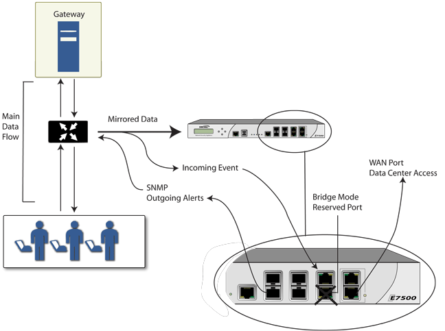
Figure 5. IPS Sniffer Mode: Network diagram
In IPS Sniffer Mode, a Layer 2 Bridge is configured between two interfaces in the same zone on the firewall, such as LAN-LAN or DMZ-DMZ. You can also create a custom zone to use for the Layer 2 Bridge. Only the WAN zone is not appropriate for IPS Sniffer Mode.
The Edit Interfaces screen available from the Network > Interfaces page provides a new checkbox called Only sniff traffic on this bridge-pair for use when configuring IPS Sniffer Mode. When selected, this checkbox causes the firewall to inspect all packets that arrive on the L2 Bridge from the mirrored switch port. The Never route traffic on this bridge-pair checkbox should also be selected for IPS Sniffer Mode to ensure that the traffic from the mirrored switch port is not sent back out onto the network.
For detailed instructions on configuring interfaces in IPS Sniffer Mode, see Configuring IPS Sniffer Mode .
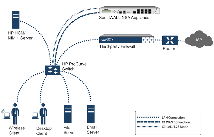
Figure 6. IPS Sniffer Mode: Sample topology
In this deployment the WAN interface and zone are configured for the internal network’s addressing scheme and attached to the internal network. The X2 port is Layer 2 bridged to the LAN port – but it won’t be attached to anything. The X0 LAN port is configured to a second, specially programmed port on the HP ProCurve switch. This special port is set for mirror mode – it will forward all the internal user and server ports to the “sniff” port on the firewall. This allows the firewall to analyze the entire internal network’s traffic, and if any traffic triggers the security signatures it will immediately trap out to the PCM+/NIM server via the X1 WAN interface, which then can take action on the specific port from which the threat is emanating.
To configure this deployment, navigate to the Network > Interfaces page and click on the configure icon for the X2 interface. On the X2 Settings page, set the IP Assignment to Layer 2 Bridged Mode and set the Bridged To: interface to X0. Select the checkbox for Only sniff traffic on the bridge-pair. Click OK to save and activate the change.
Next, go to the Network > Interfaces page and click on the configure icon for the X1 WAN interface. On the X1 Settings page, assign it a unique IP address for the internal LAN segment of your network – this may sound wrong, but this will actually be the interface from which you manage the appliance, and it is also the interface from which the appliance sends its SNMP traps as well as the interface from which it gets security services signature updates. Click OK.
|
TIP: Informational videos with interface configuration examples are available online. For example, see How to configure the SonicWALL WAN / X1 Interface with PPPoE Connection. Additional videos are available at: https://support.software.dell.com/videos-product-select.
|

