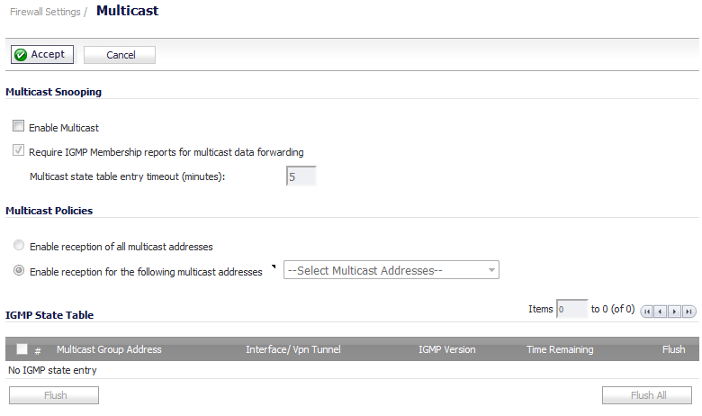
The Firewall Settings > Multicast page allows you to manage multicast traffic on the firewall.
This section provides configuration tasks for Multicast Snooping.
|
•
|
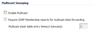
Enable Multicast - This checkbox is disabled by default. Select this checkbox to support multicast traffic.
|
|
•
|
Require IGMP Membership reports for multicast data forwarding - This checkbox is enabled by default. Select this checkbox to improve performance by regulating multicast data to be forwarded to only interfaces joined into a multicast group address using IGMP.
|
|
•
|
Multicast state table entry timeout (minutes) - This field has a default of 5. The value range for this field is 5 to 60 (minutes). Update the default timer value of 5 in the following conditions:
|
This section provides configuration tasks for Multicast Policies.
|
•
|
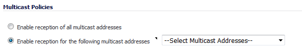
Enable reception of all multicast addresses - This radio button is not enabled by default. Select this radio button to receive all (class D) multicast addresses.
|
|
•
|
Enable reception for the following multicast addresses - This radio button is enabled by default. In the drop-down menu, select Create a new multicast object or Create new multicast group.
|
|
1
|
In the Enable reception for the following multicast addresses drop-down menu, select Create new multicast object. The Add Address Object dialog displays.
|
|
2
|
Configure the name of the address object in the Name field.
|
|
3
|
|
4
|
|
•
|
Host or Network, the IP Address field displays. Enter the IP address of the host or network. The IP address must be in the range for multicast: 224.0.0.0 to 239.255.255.255.
|
|
•
|
Network, the Netmask field displays. Enter the netmask for the network.
|
|
•
|
Range, the Starting IP Address and Ending IP Address fields display. Enter the starting and ending IP address for the address range. The IP addresses must be in the range for multicast: 224.0.0.1 to 239.255.255.255.
|
|
6
|
Click OK.
|
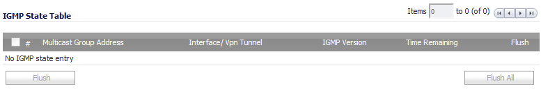
This section provides descriptions of the fields in the IGMP State Table.
|
•
|
Multicast Group Address—Provides the multicast group address the interface is joined to.
|
|
•
|
Interface / VPN Tunnel—Provides the interface (such as LAN) for the VPN policy.
|
|
•
|
|
•
|
|
•
|
Flush — Provides an icon to flush that particular entry.
|
|
•
|
Flush and Flush All buttons—To flush a specific entry immediately, check the box to the left of the entry and click Flush. Click Flush All to immediately flush all entries.
|
|
1
|
Go to the Firewall Settings > Multicast page.
|
|
2
|
|
3
|
|
4
|
Click Accept.
|
|
5
|
Go to the Network > Interfaces page.
|
|
6
|
Click the Configure button for the LAN interface you want to configure. The Edit Interface dialog displays.
|
|
7
|
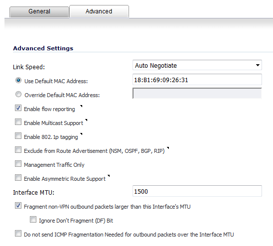
Click the Advanced tab.
|
|
8
|
Select Enable Multicast Support.
|
|
9
|
Click OK.
|
|
1
|
|
2
|
|
3
|
|
4
|
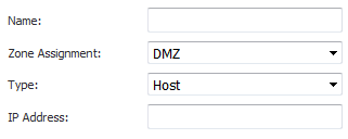
From the drop-down menu, select Create new multicast address object. The Add Address Object dialog appears.
|
|
5
|
In the Name field, enter a name for your multicast address object.
|
|
6
|
From the Zone Assignment drop-down menu, select a zone: LAN, WAN, DMZ, VPN, SSLVPN, MGMT, MULTICAST, or WLAN.
|
|
7
|
When you select a type from the Type drop-down menu, the other options change, depending on the selection. If you select:
|
|
•
|
|
•
|
Range, enter the starting and ending IP addresses in the Starting IP Address and the Ending IP Address.
|
|
•
|
Network, enter the network IP address in the Netmask field and a netmask or prefix length in the Netmask/Prefix Length field.
|
|
•
|
MAC, enter the MAC address in the MAC Address field and select the Multi-homed host checkbox (which is selected by default).
|
|
•
|
FQDN, enter the FQDN hostname in the FQDN Hostname field.
|
|
8
|
Click OK.
|
|
9
|
Go to the VPN > Settings page.
|
|
10
|
In the VPN Policies table, click the Configure icon for the Group VPN policy you want to configure. The VPN Policy dialog displays.
|
|
11
|
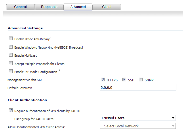
Click the Advanced tab.
|
|
12
|
|
13
|
Click OK.
|
|
a
|
Navigate to the Firewall Settings > Multicast page.
|
|
b
|
Check the Enable Multicast checkbox.
|
|
c
|
Click the Accept button.
|
|
a
|
Navigate to the Network > Interfaces page
|
|
b
|
|
c
|
Click the Advanced tab.
|
|
d
|
Select the Enable Multicast Support checkbox.
|
|
e
|
Click OK.
|
|
a
|
Navigate to the VPN > Settings page.
|
|
b
|
|
c
|
Click the Advanced tab.
|
|
d
|
|
e
|
Click OK.
|
|
5
|
Start the multicast server application and client applications. As multicast data is sent from the multicast server to the multicast group (224.0.0.0 through 239.255.255.255), the firewall queries its IGMP state table for that group to determine where to deliver that data. Similarly, when the appliance receives that data at the VPN zone, the appliance queries its IGMP State Table to determine where it should deliver the data.
|
The IGMP State Tables (upon updating) should provide information indicating that there is a multicast client on the X3 interface, and across the vpnMcastServer tunnel for the 224.15.16.17 group.
|
NOTE: By selecting Enable reception of all multicast addresses, you might see entries other than those you are expecting to see when viewing your IGMP State Table. These are caused by other multicast applications that might be running on your hosts.
|