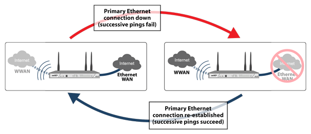
The following diagram depicts the sequence of events that occur when the WAN Ethernet connection fails and the 3G/4G Connection Profile is configured for Persistent Connection.
|
1
|
Primary Ethernet connection available – The Ethernet WAN interface is connected and used as the primary connection. The U0/U1/M0 interface is never connected while the Ethernet WAN interface is available (unless an explicit route has been configured which specifies 3G/4G as the destination interface).
|
|
2
|
Primary Ethernet connection fails – The U0/U1/M0 interface is initiated and remains in an “always-on” state while the Ethernet WAN connection is down.
|
|
3
|
Reestablishing Primary Ethernet Connectivity After Failover – When the Ethernet WAN connection (either the primary WAN port or the secondary WAN port, if so configured) becomes available again, all LAN-to-WAN traffic is automatically routed back to the available Ethernet WAN connection. This includes active connections and VPN connections. The U0/U1/M0 interface connection is closed.
|
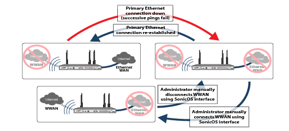
The following diagram depicts the sequence of events that occur when the WAN Ethernet connection fails and the 3G/4G Connection Profile is configured for Connect on Data.
|
1
|
Primary Ethernet connection available – The Ethernet WAN interface is connected and used as the primary connection. 3G/4G is never connected while the Ethernet WAN interface is available (unless an explicit route has been configured which specifies the U0/U1/M0 interface as the destination interface).
|
|
2
|
Primary Ethernet Connection Fails – The U0/U1/M0 interface connection is not established until qualifying outbound data attempts to pass through the Dell SonicWALL appliance.
|
|
3
|
3G/4G Connection Established – The U0/U1/M0 interface connection is established when the device or a network node attempts to transfer qualifying data to the Internet. The U0/U1/M0 interface stays connected until the Maximum Connection Time (if configured) is reached.
|
|
4
|
Reestablishing WAN Ethernet Connectivity After Failover – When an Ethernet WAN connection becomes available again or the inactivity timer (if configured) is reached, all LAN-to-WAN traffic is automatically routed back to the available Ethernet WAN connection. The U0/U1/M0 interface connection is terminated.
|
|
1
|
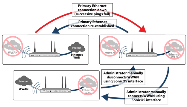
Primary Ethernet Connection Available - The Ethernet WAN is connected and used as the primary connection. 3G/4G is never connected while the Ethernet WAN connection is available.
|
|
2
|
Primary Ethernet Connection Fails - The U0/U1/M0 interface connection is not established until the administrator manually enables the connection.
|
|
3
|
3G/4G Connection Established – A U0/U1/M0 interface connection is established when the administrator manually enables the connection on the Dell SonicWALL appliance. The U0/U1/M0 interface stays connected until the administrator manually disables the connection.
|
|
4
|
Reestablishing WAN Ethernet Connectivity After Failover – Regardless of whether an Ethernet connection becomes available again, all LAN-to-WAN traffic will still use the manually enabled 3G/4G connection until the connection is manually disabled by the administrator. After a manual disconnect, the available Ethernet connection will be used.
|


