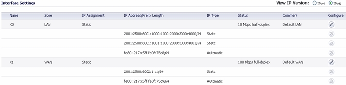
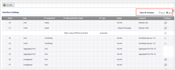
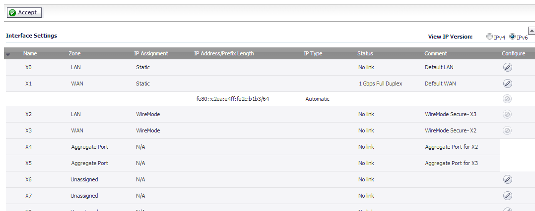
IPv6 interfaces are configured on the Network > Interfaces page by clicking the IPv6 option for the View IP Version radio button at the top right corner of the page.
|
•
|
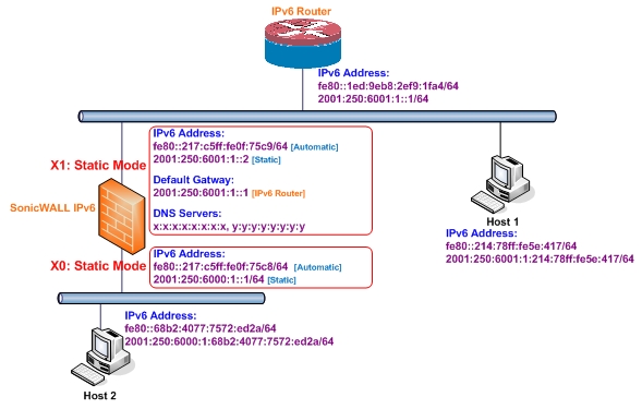
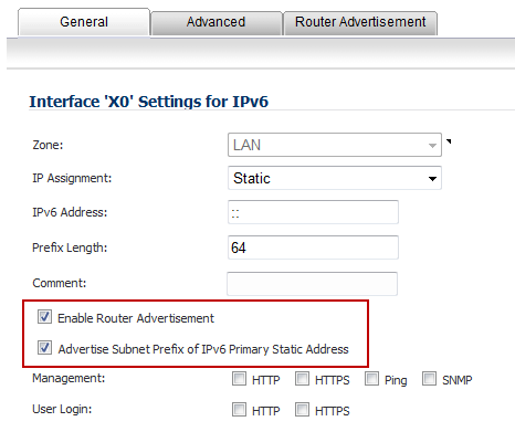
Figure 65. IPv6 static mode configuration
|
1
|
Navigate to the Network > Interfaces page.
|
|
2
|
Click on the IPv6 button at the top right corner of the page. IPv6 addresses for the appliance are displayed.
|
|
3
|
Click on the Configure icon for the interface you want to configure an IPv6 address for. The Edit Interface window displays.
|
|
NOTE: The zone assignment for interfaces must be configured on the IPv4 addressing page. To modify the zone assignment for an IPv6 interface, click the IPv4 button at the top right of the page, modify the zone for the interface, and then return to the IPv6 interface page.
|
|
4
|
|
5
|
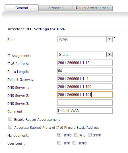
Enter the IPv6 Address for the interface.
|
|
6
|
Enter the Prefix Length for the address.
|
|
7
|
If this is the primary WAN interface, enter the IPv6 address of the Default Gateway. If this is not the primary WAN interface, any Default Gateway entry will be ignored, so you can leave this as ::. (The double colon is the abbreviation for an empty address, or 0:0:0:0:0:0:0:0.)
|
|
8
|
If this is the primary WAN interface, enter up to three DNS Server IPv6 addresses. Again, if this is not the primary WAN interface, any DNS Server entries will be ignored.
|
|
9
|
Select Enable Router Advertisement to make this an advertising interface that distributes network and prefix information.
|
|
10
|
Select Advertise Subnet Prefix of IPv6 Primary Static Address to add a default prefix into the interface advertising prefix list. This prefix is the subnet prefix of interface IPv6 primary static address. This option will help all hosts on the link stay in the same subnet.
|
|
1
|
|
2
|
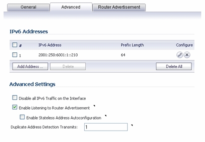
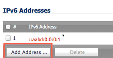
Click the Add Address button to configure multiple static IPv6 addresses for the interface.
|
|
3
|
Enter the IPv6 Address for the additional address for the interface.
|
|
4
|
Enter the Prefix Length for the address.
|
|
5
|
Select Advertise Subnet Prefix of IPv6 Primary Static Address to add a default prefix into the interface advertising prefix list. This prefix is the subnet prefix of interface IPv6 primary static address. This option will help all hosts on the link stay in the same subnet.
|
|
6
|
Click OK.
|
|
7
|
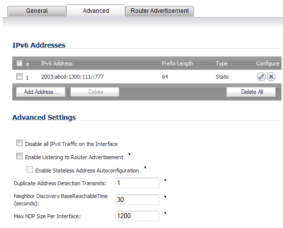
The following additional options can be configured on the Advanced tab under the Advanced Settings heading:
|
|
•
|
Select Disable all IPv6 Traffic on the Interface to stop the interface from handling all IPv6 traffic. Disabling IPv6 traffic can improve firewall performance for non-IPv6 traffic. If the firewall is deployed in a pure IPv4 environment, Dell SonicWALL recommends enabling this option.
|
|
•
|
Select Enable Listening to Router Advertisement to have the firewall receive router advertisement. If disabled, the interface filters all incoming Router Advertisement message, which can enhance security by eliminating the possibility of receiving malicious network parameters (for example, prefix information or default gateway). This option is not visible for Auto mode. In Auto mode, it is always enabled.
|
|
•
|
Select Enable Stateless Address Autoconfiguration to allow autonomous IPv6 addresses to be assigned to this interface. If unchecked, all assigned autonomous IPv6 address will be removed from this interface. This option is not visible for Auto mode. In Auto mode, it is always enabled.
|
|
•
|
Enter a numeric value for Duplicate Address Detection Transmits to specify the number of consecutive Neighbor Solicitation messages sent while performing Duplicate Address Detection (DAD) before assigning a tentative address to interface. A value of 0 indicates that DAD is not performed on the interface.
|
|
1
|
|
2
|
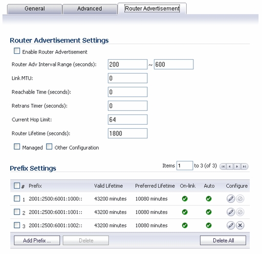
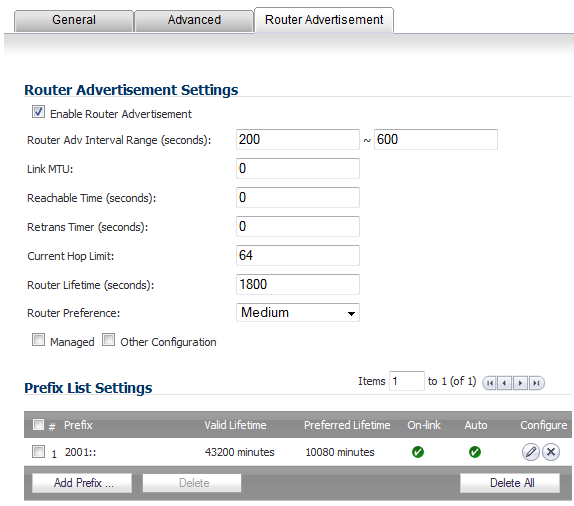
Select the Enable Router Advertisement checkbox to have make this an advertising interface that will distribute network and prefix information.
|
|
•
|
Router Adv Interval Range - The time interval allowed between sending unsolicited multicast Router Advertisements from the interface, in seconds.
|
|
•
|
Link MTU - The recommended MTU for the interface link. A value of 0 means firewall will not advertise link MTU for the link.
|
|
•
|
Reachable Time - The time that a node assumes a neighbor is reachable after having received a reachability confirmation. A value of 0 means this parameter is unspecified by this firewall.
|
|
•
|
Retrans Time - The time between retransmitted Neighbor Solicitation messages. A value of 0 means this parameter is unspecified by this firewall.
|
|
•
|
Current Hop Limit - The default value that should be placed in the Hop Count field of the IP header for outgoing IP packets. A value of 0 means this parameter is unspecified by this firewall.
|
|
•
|
Router Lifetime - The lifetime when firewall is accepted as a default router. A value of 0 means that the router is not a default router.
|
|
4
|
Select the Managed checkbox to set the managed address configuration flag in the Router Advertisement message. If set, it indicates that IPv6 addresses are available via Dynamic Host Configuration Protocol.
|
|
5
|
Select the Other Configuration checkbox to set the Other configuration flag in Router Advertisement message. If set, it indicates that other configuration information is available via Dynamic Host Configuration Protocol.
|
|
1
|
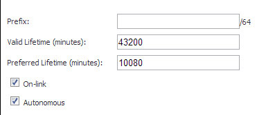
Click the Add Prefix button to configure an advertising prefix. Advertising prefixes are used for providing hosts with prefixes for on-link determination and Address Autoconfiguration.
|
|
2
|
Enter the Prefix that is to be advertised with the Router Advertisement message.
|
|
3
|
Enter the Valid Lifetime to set the length of time (in minutes) that the prefix is valid for the purpose of on-link determination. A value of “71582789” means the lifetime is infinite.
|
|
4
|
Enter the Preferred Lifetime to set the length of time that addresses generated from the prefix via stateless address autoconfiguration remain preferred. A value of “71582789” means the lifetime is infinite.
|
|
5
|
Optionally click the On-link checkbox to enable the on-link flag in Prefix Information option, which indicates that this prefix can be used for on-link determination.
|
|
6
|
Optionally click the Autonomous checkbox to enable the autonomous address-configuration flag in Prefix Information option, which indicates that this prefix can be used for stateless address configuration.
|
|
7
|
Click OK.
|
|
•
|
DHCPv6 stateful mode: DHCPv6 clients require IPv6 address together with other network parameters (for example, DNS Server, Domain Name).
|
|
•
|
DHCPv6 stateless mode: DHCPv6 client only obtains network parameters other than IPv6 address. Choosing which kind of those modes depends on Managed (M) Address Configuration and Other (O) Configuration flag in the advertised Router Advertisement message:
|
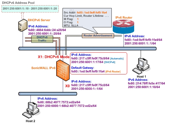
Figure 66. DHCPv6 topology
|
1
|
Navigate to the Network > Interfaces page.
|
|
2
|
If you are configuring an unassigned interface, click the IPv4 radio button at the top right corner of the page.
|
|
3
|
|
4
|
|
5
|
|
6
|
Click OK.
|
|
7
|
Click on the IPv6 button at the top right corner of the page. IPv6 addresses for the appliance are displayed.
|
|
8
|
Click on the Configure icon for the interface you want to configure an IPv6 address for. The Edit Interface window displays.
|
|
9
|
|
•
|
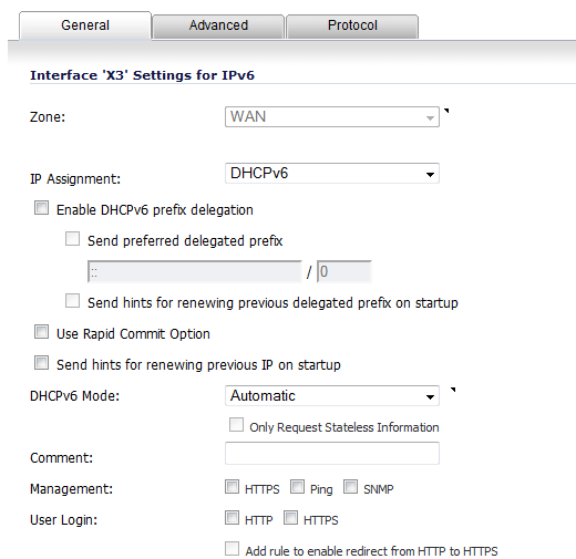
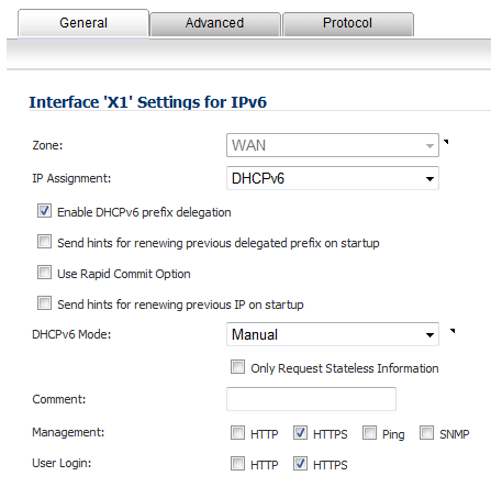
Enable DHCPv6 prefix delegation - If enabled, these options become available:
|
|
•
|
Send preferred delegated prefix - Select this option to require a DHCAPv6 client to try to send the preferred delegated prefix specified in the two fields.
|
|
•
|
Send hints for renewing previous delegated prefix on startup - Select this option to require a DHCPv6 client to try to renew the delegated prefix assigned before when the firewall started up.
|
|
•
|
Use Rapid Commit Option - If enabled, DHCPv6 client use Rapid Commit Option to use the two message exchange for address assignment.
|
|
•
|
Send hints for renewing previous IP on startup - If enabled, DHCPv6 client will try to renew the address assigned before when firewall startup.
|
|
11
|
Set the DHCPv6 Mode for the interface. As required by RFC, DHCPv6 client depends on Router Advertisement message to decide which mode (stateful or stateless) it should choose. This definition will limit user's choice if they want to determine DHCPv6 mode by itself. Dell SonicWALL’s implementation of DHCPv6 defines two different modes to balance the conformance and flexibility:
|
|
•
|
Automatic - In this mode, IPv6 interface configures IPv6 addresses using stateless/stateful autoconfiguration in accord with the M and O settings in the most recently received router advertisement message.
|
|
•
|
Manual - In Manual mode, DHCPv6 mode is manually configured regardless of any received Router Advertisement. The Only Request Stateless Information option will determine which DHCPv6 mode is used. If this option is unchecked, DHCPv6 client is under stateful mode; if it is checked, DHCPv6 client is under stateless mode and only obtains network parameters.
|
|
12
|
Optionally, select the Only Request Stateless Information checkbox to have DHCPv6 clients only requests network parameter setting from the DHCPv6 server. The IPv6 address is assigned through stateless auto-configuration.
|
|
13
|
|
14
|
Optionally click the Advanced tab to configure Advanced options and/or click the Protocol tab to view DHCPv6 stateful and stateless configuration information.
|
|
15
|
Click OK to complete the configuration.
|
The following options can be configured on the Advanced tab of the IPv6 Edit Interface dialog box:
|
•
|
Select Disable all IPv6 Traffic on the Interface to stop the interface from handling all IPv6 traffic. Disabling IPv6 traffic can improve firewall performance for non-IPv6 traffic. If the firewall is deployed in a pure IPv4 environment, Dell SonicWALL recommends enabling this option.
|
|
•
|
Select Enable Listening to Router Advertisement to have the firewall receive router advertisement. If disabled, the interface filters all incoming Router Advertisement message, which can enhance security by eliminating the possibility of receiving malicious network parameters (e.g. prefix information or default gateway). This option is not visible for Auto mode. In Auto mode, it is always enabled.
|
|
•
|
Select Enable Stateless Address Autoconfiguration to allow autonomous IPv6 addresses to be assigned to this interface. If unchecked, all assigned autonomous IPv6 address will be removed from this interface. This option is not visible for Auto mode. In Auto mode, it is always enabled.
|
|
•
|
Enter a numeric value for Duplicate Address Detection Transmits to specify the number of consecutive Neighbor Solicitation messages sent while performing Duplicate Address Detection (DAD) before assigning a tentative address to interface. A value of 0 indicates that DAD is not performed on the interface.
|
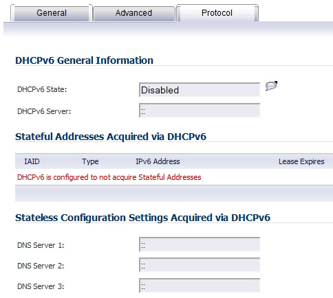
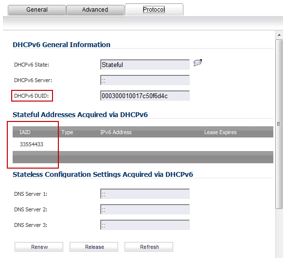
When configuring an IPv6 interface in DHCpv6 mode, the Protocol tab displays additional DHCPv6 information.
|
•
|
DHCPv6 State: If the interface is configured for Stateless mode, the DHCPv6 State will be Stateless. If the interface is configured for Stateful mode, the DHCPv6 State will be either Enable or Disabled. When the interface is in Stateful, DHCPv6 mode, mousing over the icon to the left of the DHCPv6 State will display current Router Advertisement information for the interface.
|
|
•
|
DHCPv6 Server: The IPv6 address of the DHCPv6 server.
|
|
•
|
Stateful Addresses Acquired via DHCPv6: Displays information on any acquired stateful IPv6 addresses.
|
|
•
|
DNS Servers: The IPv6 addresses of any DNS Servers.
|
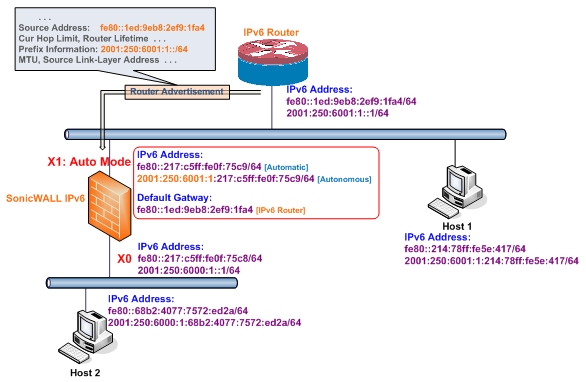
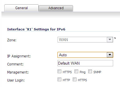
Figure 67. IPv6 auto mode configuration
|
1
|
Navigate to the Network > Interfaces page.
|
|
2
|
Click on the IPv6 button at the top right corner of the page to display IPv6 addresses.
|
|
3
|
Click on the Configure icon for the interface you want to configure an IPv6 address for. The Edit Interface dialog box displays.
|
|
4
|
|
5
|
Optionally, you can select enter a numeric value for Duplicate Address Detection Transmits on the Advanced tab to specify the number of consecutive Neighbor Solicitation messages sent while performing Duplicate Address Detection (DAD) before assigning a tentative address to interface. A value of 0 indicates that DAD is not performed on the interface.
|
|
6
|
Click OK.
|
The procedure for configuring a VLAN Sub-interface in IPv6 is identical to that in IPv4. Refer to Configuring VLAN Subinterfaces for details.
The procedure for configuring a Wire Mode interface in IPv6 is identical to that in IPv4. Refer to Configuring an Interface for Wire Mode for details.
Figure 68. IPv6 to IPv4 tunnel interface
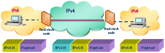
6to4 tunnels use a prefix of the form 2002:tunnel-IPv4-address::/48 to tunnel IPv6 traffic over IPv4 (for example, if the tunnel’s IPv4 endpoint has the address a01:203, the 6to4 tunnel prefix is 2002:a01:203::1). Routers advertise a prefix of the form 2002:[IPv4]:xxxx/64 to IPv6 clients. For complete information, see RFC 3056.
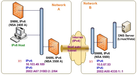
Figure 69. 6to4 auto tunnel topology
|
1
|
Navigate to the Network > Interfaces page.
|
|
2
|
|
3
|
Select the Zone for the 6to4 tunnel interface. This is typically the WAN interface.
|
|
4
|
|
5
|
|
6
|
Select the Enable IPv6 6to4 Tunnel checkbox. By default, this checkbox is selected.
|
|
7
|
|
NOTE: Selecting HTTPS enables the Add rule to enable redirect from HTTP to HTTPS option automatically. The Add rule to enable redirect from HTTP to HTTPS option cannot be selected for the other protocols.
|
|
8
|
|
NOTE: Selecting only HTTPS enables the Add rule to enable redirect from HTTP to HTTPS option automatically. If you also select HTTP, the Add rule to enable redirect from HTTP to HTTPS option is deselected and cannot be selected.
|
|
9
|
Click OK.
|
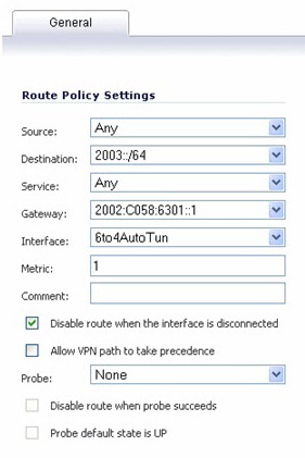
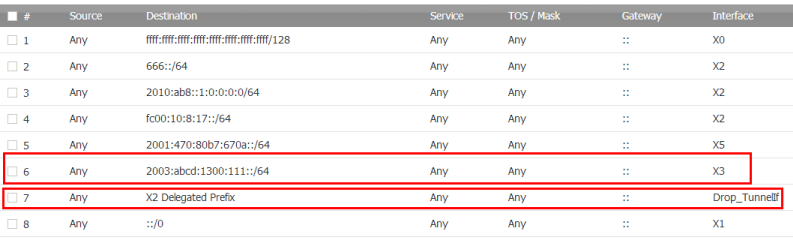
To enable 6to4 relay, go to Network > Routing. Then, click the Add button to create a Route Policy that can route all traffic destined for 2003 prefixes over the 6to4 auto tunnel interface, as shown in the following example:
|
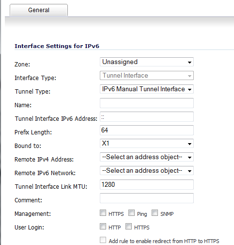
1
|
Navigate to the Network > Interfaces page.
|
|
2
|
|
3
|
Select the Zone for the tunnel interface.
|
|
4
|
|
5
|
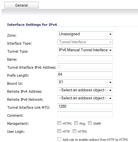
Enter a Name for the tunnel interface.
|
|
6
|
|
7
|
Select an interface to which the tunnel is bound from the Bound to drop-down menu. The default is X1.
|
|
8
|
From the Remote IPv4 Address drop-down menu, select an IPv4 address object for the tunnel endpoint.
|
|
9
|
From the Remote IPv6 network drop-down menu, select an IPv6 Address object, which can be a group, range, network, or host.
|
|
10
|
|
NOTE: Selecting HTTPS enables the Add rule to enable redirect from HTTP to HTTPS option automatically. The Add rule to enable redirect from HTTP to HTTPS option cannot be selected for the other protocols.
|
|
11
|
|
NOTE: Selecting only HTTPS enables the Add rule to enable redirect from HTTP to HTTPS option automatically. If you also select HTTP, the Add rule to enable redirect from HTTP to HTTPS option is deselected and cannot be selected.
|
|
12
|
Click OK.
|
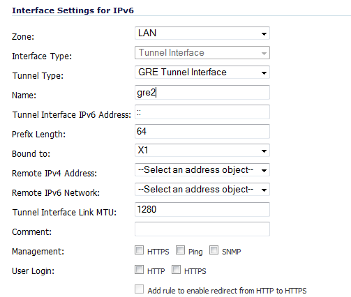
Figure 70. GRE IPv6 tunnel configuration
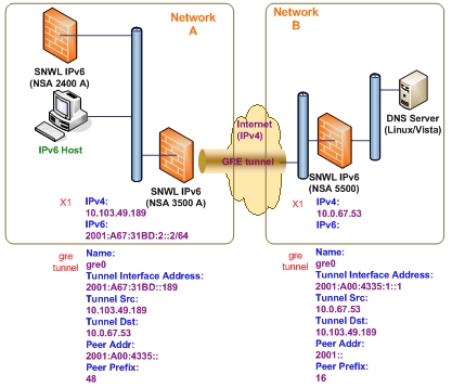
The configuration of a GRE tunnel is similar to a manual tunnel, except GRE Tunnel Interface is selected for the Tunnel Type.
When the firewall starts, a default address object group called Prefixes from DHCPv6 Delegation is automatically created. Prefixes delegated from the upstream interface are members of this group.
|
1
|
Go to the Network > Interfaces page.
|
|
2
|
|
3
|
Click the Edit icon in the Configure column for the Interface you want to configure as the upstream interface. The Edit Interface dialog appears.
|
|
4
|
|
5
|
Select the Enable DHCPv6 prefix delegation option.
|
|
6
|
|
7
|
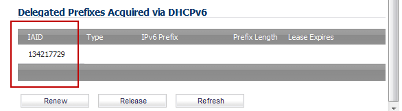
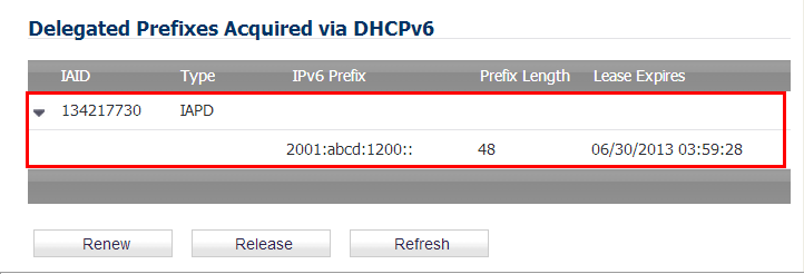
To see the configured DHCPv6 information, click the Protocol tab.
|
|
8
|
Click the Renew button. The information for the other columns is displayed.
|
|
1
|
Go to the Network > Interfaces page.
|
|
2
|
Select the IPv6 option.
|
|
3
|
Click the Edit icon in the Configure column for the Interface you want to configure as the downstream interface. The Edit Interface dialog appears.
|
|
4
|
Select the Enable Router Advertisement option.
|
|
5
|
Click the Advanced tab.
|
If the upstream prefix is obtained, it is displayed in the IPv6 Addresses panel.
|
6
|
If the upstream prefix cannot be obtained, an alternate address is displayed in the IPv6 Addresses panel.
|
|
7
|
|
8
|
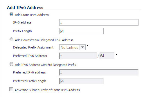
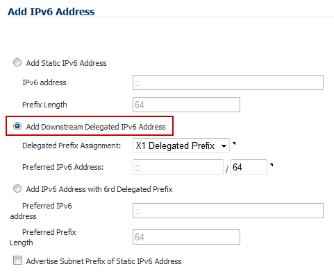
Select the Add Downstream Delegated IPv6 Address option.
|
|
9
|
(Optional) Select the Advertise Subnet Prefix of Static IPv6 Address option.
|
|
10
|
Click the Router Advertisement tab.
|
|
11
|
Select the Enable Router Advertisement option.
|
If you selected Advertise Subnet Prefix of Static IPv6 Address option under the General tab, the prefix is listed in the Prefix List Settings panel.
|
12
|
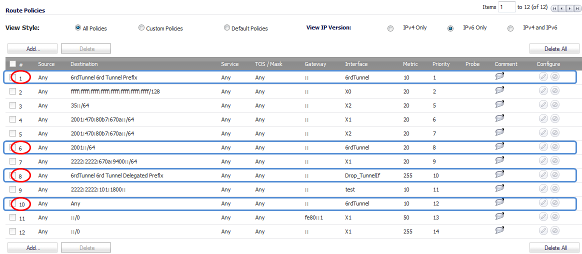
To see your new IPv6 PD interfaces, go to the Network > Routing page.
|
|
13
|
Select the IPv6 option.
|
On the Network > Routing page, in the Route Policies panel, there are four default route policies for 6rd tunnel interfaces.
|
•
|
|
•
|
|
1
|
Go to the Network > Interfaces page.
|
|
2
|
|
3
|
|
4
|
|
5
|
The Interface Type menu is disabled. It already has Tunnel Interface selected as it was selected from the Add Interface menu in Step 3.
|
|
6
|
|
8
|
In the Tunnel Interface IPv6 Address box, enter the IPv6 address of the tunnel interface. For example, 2001::2.
|
|
9
|
|
10
|
|
11
|
|
12
|
|
13
|
|
14
|
|
15
|
|
16
|
(Optional) In the Comment field, enter a comment to describe the tunnel interface.
|
|
17
|
Select the Add Default Route Automatically option.
|
|
18
|
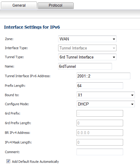
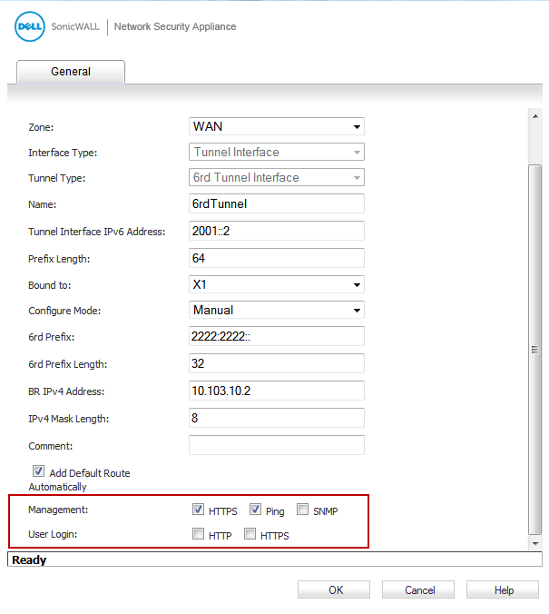
If you selected Manual as the Configure Mode, your 6rd Tunnel Interface settings are shown under the General tab.
If you selected DHCP as the Configure Mode, your 6rd Tunnel Interface settings are shown under the Protocol tab.
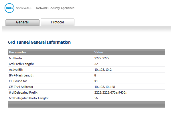
Figure 71 shows the delivery of ISATAP traffic between ISATAP hosts on the same logical ISATAP subnet:
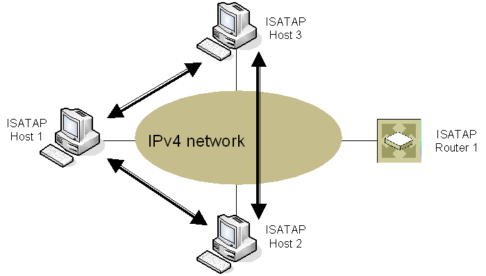
Figure 72 shows the delivery of ISATAP traffic between hosts on different ISATAP subnets:
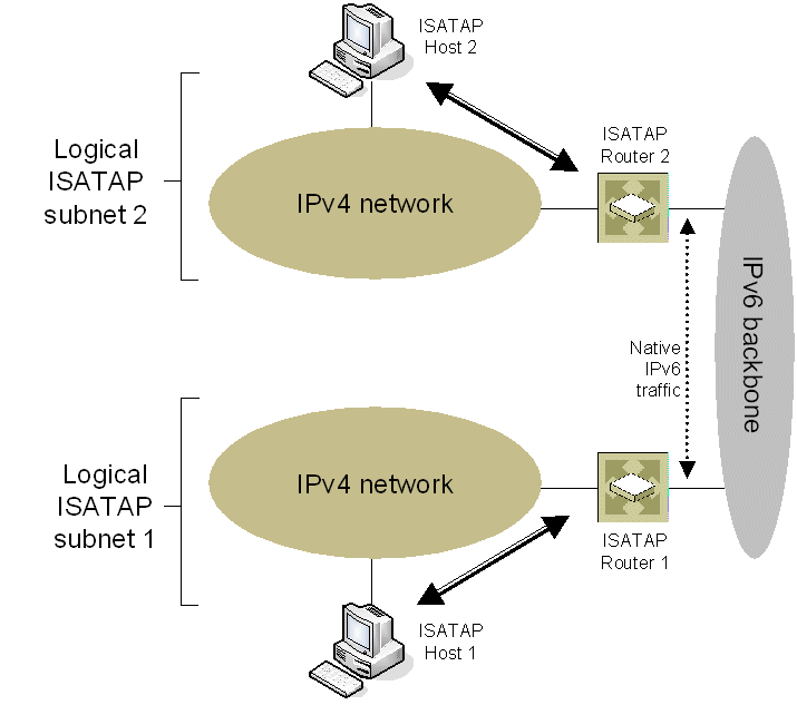
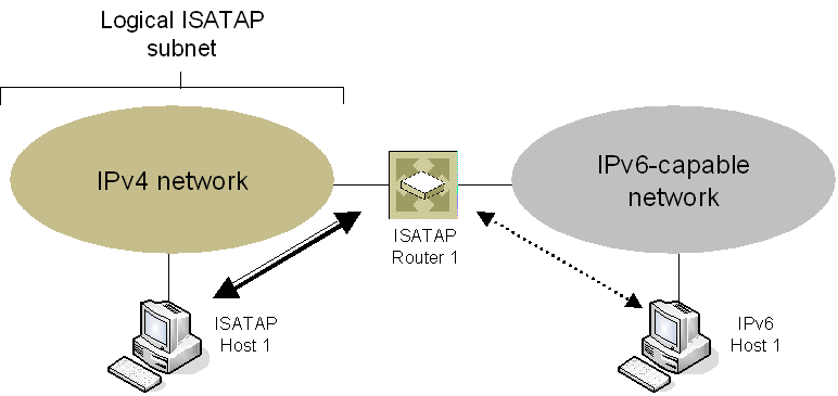
Figure 73 shows the delivery of packets between ISATAP hosts and hosts on an IPv6-capable network.
|
1
|
|
2
|
Click the Add Interface button.
|
|
3
|
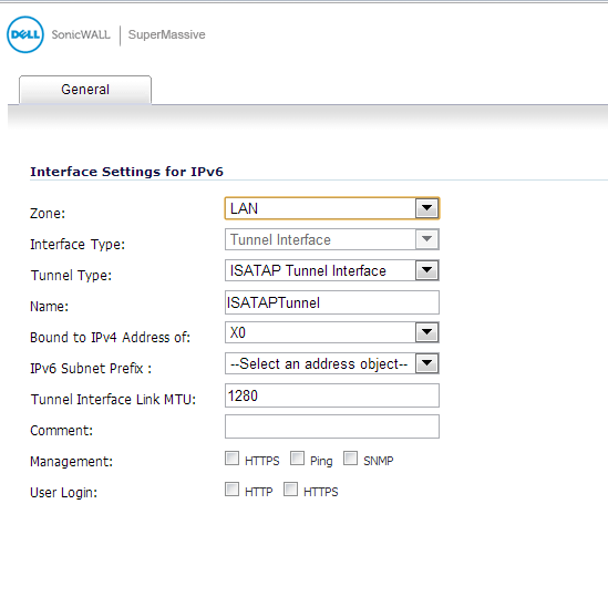
In the General tab, Select the Zone for the tunnel interface.
|
|
4
|
|
5
|
Enter a Name for the tunnel interface.
|
|
6
|
Bound to IPv4 Address of - Select an interface from the drop-down list. The ISATAP tunnel uses the IPv4 address of the bound interface as the IPv4 end address of 6over4 tunnel.
|
|
7
|
IPv6 Subnet Prefix - Select an address object from the drop-down list (or select Create a new address object). The IPv6 subnet prefix is a 64 bit prefix, and is used by ISATAP hosts for ISATAP address auto configuration.
|
|
8
|
Tunnel Interface Link MTU - The recommended MTU for the interface link. A value of 0 means firewall will not advertise link MTU for the link.
|
|
9
|
Enter any optional comment text in the Comment field. This text is displayed in the Comment column of the Interface table.
|
|
10
|
|
11
|
If you want to allow selected users with limited management rights to log in to the security appliance, select HTTP and/or HTTPS in User Login.
|
|
1
|
Navigate to the Firewall Settings > Advanced page.
|
|
2
|
Locate the IPv6 Advanced Configurations section.
|
|
•
|
Enable NetBIOS name query response for ISATAP – Select this to if you want the security appliance to answer a NetBIOS query in order to help ISATAP hosts resolve the name into an IPv4 address.
|
|
•
|
Resolved name ISATAP is valid for (seconds) – Enter a time period (in seconds).
|
|
•
|
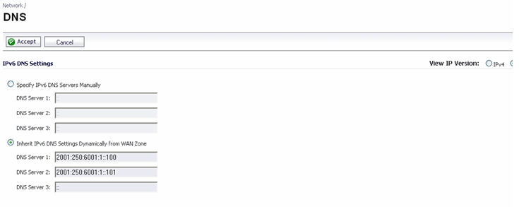
DNS for IPv6 is configured using the same method as for IPv4. Click the IPv6 option in the View IP Version radio button at the top left of the Network > DNS page.
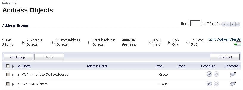
IPv6 address objects or address groups can be added in the same manner as IPv4 address objects. On the Network > Address Objects page, the View IP Version radio button has three options: IPv4 only, IPv6 only, or IPv4 and IPv6.
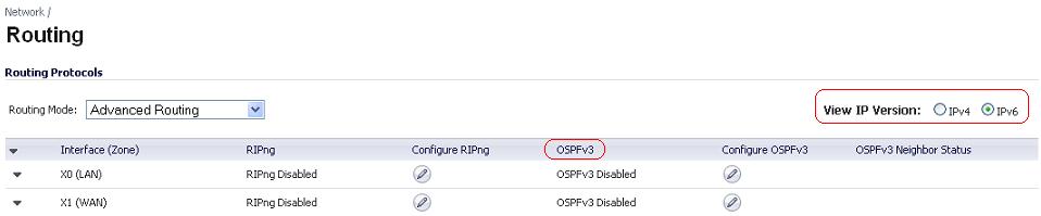
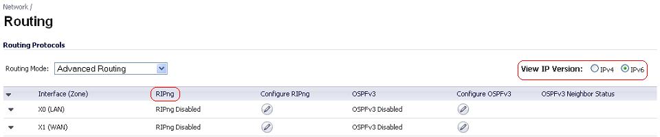
Policy Based Routing is fully supported for IPv6 by selecting IPv6 address objects and gateways for route policies on the Network > Routing page. On the Network > Routing page, the View IP Version radio button has three options: IPv4 only, IPv6 only, or IPv4 and IPv6. The OSPF feature displays two radio buttons to switch between version 2 and version 3.
NAT policies can be configured for IPv6 by selecting IPv6 address objects on the Network > NAT Policies page. On the Network > NAT Policies page, the View IP Version radio button has three options: IPv4 only, IPv6 only, or IPv4 and IPv6.
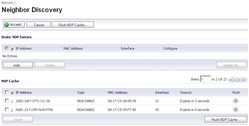
|
1
|
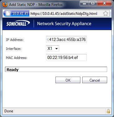
|
2
|
In the IP Address field, enter the IPv6 address for the remote device.
|
|
3
|
In the Interface drop-down menu, select the interface on the firewall that will be used for the entry.
|
|
4
|
In the MAC Address field, enter the MAC address of the remote device.
|
|
5
|
Click OK. The static NDP entry is added.
|
DHCPv6 server can be configured similar to IPv4 after selecting the IPv6 option in the View IP Version radio button at the top left of the Network > DNS page.
IPv6 firewall access rules can be configured in the same manner as IPv4 access rules by choosing IPv6 address objects instead of IPv4 address objects. On the Firewall > Access Rules page, the View IP Version radio button has three options: IPv4 only, IPv6 only, or IPv4 and IPv6.
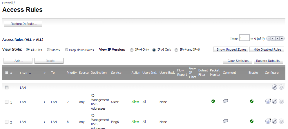
You can configure advanced firewall settings for IPv6, including packet limitations and traffic restrictions on the Firewall Settings > Advanced. See IPv6 Advanced Configuration for more information.
IPSec VPNs can be configured for IPv6 in a similar manner to IPv4 VPNs after selecting the IPv6 option in the View IP Version radio button at the top left of the VPN > Settings page.
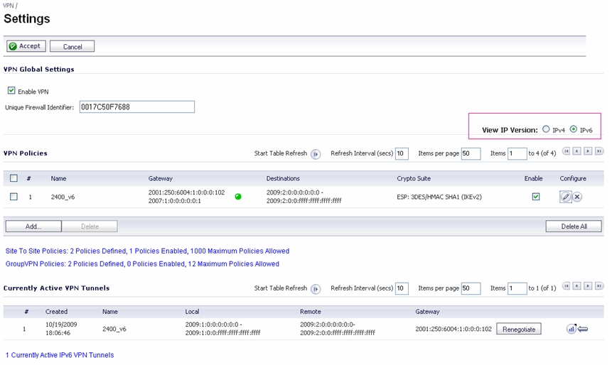
When configuring an IPv6 VPN policy, on the General tab the gateways must be configured using IPv6 addresses. FQDN is not supported. When configuring IKE authentication, IPV6 addresses can be used for the local and peer IKE IDs.
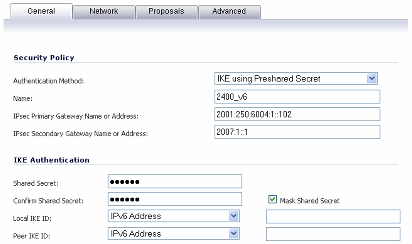
On the Network tab of the VPN policy, IPV6 address objects (or address groups that contain only IPv6 address objects) must be selected for the Local Network and Remote Network.
The Any address option for Local Networks and the Tunnel All option for Remote Networks are removed. Select an all zero IPv6 Network address object could be selected for the same functionality and behavior.
On the Proposals tab, the configuration is identical for IPv6 and IPv4, except for the fact that IPv6 only support IKEv2 mode.
On the Advanced tab, only Enable Keep Alive and the IKEv2 Settings can be configured for IPv6 VPN policies.
SonicOS supports NetExtender connections for users with IPv6 addresses. On the SSLVPN > Client Settings page, first configure the traditional IPv6 IP address pool, and then configure an IPv6 IP Pool. Clients will be assigned two internal addresses: one IPv4 and one IPv6.
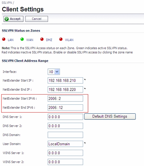
On the SSLVPN > Client Routes page, user can select a client routes from the drop-down list of all address objects including all the pre-defined IPv6 address objects.
|
NOTE: IPv6 FQDN is supported.
|