SonicOS includes L2 (Layer 2) Bridged Mode, a method of unobtrusively integrating a firewall into any Ethernet network. L2 Bridged Mode is ostensibly similar to SonicOS’s Transparent Mode in that it enables a firewall to share a common subnet across two interfaces, and to perform stateful and deep-packet inspection on all traversing IP traffic, but it is functionally more versatile.
Another aspect of the versatility of L2 Bridged Mode is that you can use it to configure IPS Sniffer Mode. Supported on Dell SonicWALL Security Appliances, IPS Sniffer Mode uses a single interface of a Bridge-Pair to monitor network traffic from a mirrored port on a switch. IPS Sniffer Mode provides intrusion detection, but cannot block malicious traffic because the firewall is not connected inline with the traffic flow. For more information about IPS Sniffer Mode, see IPS Sniffer Mode .
L2 Bridged Mode provides an ideal solution for networks that already have an existing firewall, and do not have immediate plans to replace their existing firewall but wish to add the security of SonicWALL deep-packet inspection and security services such as Intrusion Prevention Services, Gateway Anti Virus, and Gateway Anti Spyware. If you do not have SonicWALL security services subscriptions, you may sign up for free trials from the Security Service > Summary page of your SonicWALL.
You can also use L2 Bridged Mode in a High Availability deployment. This scenario is explained in the Layer 2 Bridged Mode with High Availability .
Table 25 outlines the benefits of each key feature of layer 2 bridged mode:
The following terms are used when referring to the operation and configuration of L2 Bridged Mode:
|
•
|
L2 Bridged Mode – A method of configuring a Dell SonicWALL Security Appliance, which enables the firewall to be inserted inline into an existing network with absolute transparency, beyond even that provided by Transparent Mode. Layer 2 Bridged Mode also refers to the IP Assignment configuration that is selected for Secondary Bridge Interfaces that are placed into a Bridge-Pair.
|
|
•
|
Transparent Mode – A method of configuring a Dell SonicWALL Security Appliance that allows the firewall to be inserted into an existing network without the need for IP reconfiguration by spanning a single IP subnet across two or more interfaces through the use of automatically applied ARP and routing logic.
|
|
•
|
IP Assignment – When configuring a Trusted (LAN) or Public (DMZ) interface, the IP Assignment for the interface can either be:
|
|
•
|
Static – The IP address for the interface is manually entered.
|
|
•
|
Transparent Mode – The IP address(es) for the interface is assigned using an Address Object (Host, Range, or Group) that falls within the WAN Primary IP subnet, effectively spanning the subnet from the WAN interface to the assigned interface.
|
|
•
|
Layer 2 Bridged Mode – An interface placed in this mode becomes the Secondary Bridge Interface to the Primary Bridge Interface to which it is paired. The resulting Bridge-Pair will then behave like a two-port learning bridge with full L2 transparency, and all IP traffic that passes through will be subjected to full stateful failover and deep packet inspection.
|
|
•
|
Bridge-Pair – The logical interface set composed of a Primary Bridge Interface and a Secondary Bridge Interface. The terms primary and secondary do not imply any inherent level of operational dominance or subordination; both interfaces continue to be treated according to their zone type, and to pass IP traffic according to their configured Access Rules. Non-IPv4 traffic across the Bridge-Pair is controlled by the Block all non-IPv4 traffic setting on the Secondary Bridge Interface. A system may support as many Bridge Pairs as it has interface pairs available. In other words, the maximum number of Bridge-Pairs is equal to ½ the number of physical interfaces on the platform. Membership in a Bridge-Pair does not preclude an interface from conventional behavior; for example, if X1 is configured as a Primary Bridge Interface paired to X3 as a Secondary Bridge Interface, X1 can simultaneously operate in its traditional role as the Primary WAN, performing NAT for Internet-bound traffic through the Auto-added X1 Default NAT Policy.
|
|
•
|
Primary Bridge Interface – A designation that is assigned to an interface once a Secondary Bridge Interface has been paired to it. A Primary Bridge Interface can belong to an Untrusted (WAN), Trusted (LAN), or Public (DMZ) zone.
|
|
•
|
Secondary Bridge Interface – A designation that is assigned to an interface whose IP Assignment has been configured for Layer 2 Bridged Mode. A Secondary Bridge Interface can belong to a Trusted (LAN), or Public (DMZ) zone.
|
|
•
|
Bridge Management Address – The address of the Primary Bridge Interface is shared by both interfaces of the Bridge-Pair. If the Primary Bridge Interface also happens to be the Primary WAN interface, it is this address that is uses for outbound communications by the firewall, such as NTP, and License Manager updates. Hosts that are connected to either segment of the Bridge-Pair may also use the Bridge Management Address as their gateway, as will be common in Mixed-Mode deployments.
|
|
•
|
Bridge-Partner – The term used to refer to the other member of a Bridge-Pair.
|
|
•
|
Non-IPv4 Traffic - SonicOS supports the following IP protocol types: ICMP (1), IGMP (2), TCP (6), UDP (17), GRE (47), ESP (50), AH (51), EIGRP (88), OSPF (89), PIM (103), L2TP (115). More esoteric IP types, such as Combat Radio Transport Protocol (126), are not natively handled by the firewall, nor are non-IPv4 traffic types such as IPX or (currently) IPv6. L2 Bridged Mode can be configured to either pass or drop Non-IPv4 traffic.
|
|
•
|
Captive-Bridged Mode – This optional mode of L2 Bridge operation prevents traffic that has entered an L2 bridge from being forwarded to a non-Bridge-Pair interface. By default, L2 Bridge logic will forward traffic that has entered the L2 Bridge to its destination along the most optimal path as determined by ARP and routing tables. In some cases, the most optimal path might involve routing or NATing to a non-Bridge-Pair interface. Activating Captive-Bridged Mode ensures that traffic which enters an L2 Bridge exits the L2 Bridge rather than taking its most logically optimal path. In general, this mode of operation is only required in complex networks with redundant paths, where strict path adherence is required.
|
|
•
|
Pure L2 Bridge Topology – Refers to deployments where the firewall will be used strictly in L2 Bridged Mode for the purposes of providing in-line security to a network. This means that all traffic entering one side of the Bridge-Pair will be bound for the other side, and will not be routed/NATed through a different interface. This will be common in cases where there is an existing perimeter security appliance, or where in-line security is desired along some path (for example, inter-departmentally, or on a trunked link between two switches) of an existing network. Pure L2 Bridge Topology is not a functional limitation, but rather a topological description of a common deployment in heterogeneous environments.
|
|
•
|
Mixed-Mode Topology – Refers to deployments where the Bridge-Pair will not will not be the only point of ingress/egress through the firewall. This means that traffic entering one side of the Bridge-Pair may be destined to be routed/NATed through a different interface. This will be common when the firewall is simultaneously used to provide security to one or more Bridge-Pair while also providing:
|
ARP – Address Resolution Protocol (the mechanism by which unique hardware addresses on network interface cards are associated to IP addresses) is proxied in Transparent Mode. If the Workstation on Server on the left had previously resolved the Router (192.168.0.1) to its MAC address 00:99:10:10:10:10, this cached ARP entry would have to be cleared before these hosts could communicate through the firewall. This is because the firewall proxies (or answers on behalf of) the gateway’s IP (192.168.0.1) for hosts connected to interfaces operating in Transparent Mode. So when the Workstation at the left attempts to resolve 192.168.0.1, the ARP request it sends is responded to by the firewall with its own X0 MAC address (00:06:B1:10:10:10).
The firewall also proxy ARPs the IP addresses specified in the Transparent Range (192.168.0.100 to 192.168.0.250) assigned to an interface in Transparent Mode for ARP requests received on the X1 (Primary WAN) interface. If the Router had previously resolved the Server (192.168.0.100) to its MAC address 00:AA:BB:CC:DD:EE, this cached ARP entry would have to be cleared before the router could communicate with the host through the firewall. This typically requires a flushing of the router’s ARP cache either from its management interface or through a reboot. Once the router’s ARP cache is cleared, it can then send a new ARP request for 192.168.0.100, to which the firewall will respond with its X1 MAC 00:06:B1:10:10:11.
L2 Bridged Mode employs a learning bridge design where it dynamically determines which hosts are on which interface of an L2 Bridge (referred to as a Bridge-Pair). ARP is passed through natively, meaning that a host communicating across an L2 Bridge sees the actual host MAC addresses of their peers. For example, the Workstation communicating with the Router (192.168.0.1) sees the router as 00:99:10:10:10:10, and the Router sees the Workstation (192.168.0.100) as 00:AA:BB:CC:DD:EE.
|
NOTE: Stream-based TCP protocols communications (for example, an FTP session between a client and a server) need to be re-established upon the insertion of an L2 Bridged Mode firewall. This is by design so as to maintain the security afforded by stateful packet inspection. As the stateful packet inspection engine can not have knowledge of the TCP connections that pre-existed it, it drops these established packets with a log event such as TCP packet received on non-existent/closed connection; TCP packet dropped.
|
Figure 7. L2 Bridge IP packet flow
![]()
The following sequence of events describes the flow diagram in Figure 7:
|
•
|
In general, the destination for packets entering an L2 Bridge will be the Bridge-Partner interface (that is, the other side of the bridge). In these cases, no translation will be performed.
|
|
•
|
In cases where the L2 Bridge Management Address is the gateway, as is sometimes the case in Mixed-Mode topologies, then NAT is applied as needed (see the L2 Bridge Path Determination section for more details).
|
|
7
|
Firewall Access Rules are applied to the packet. For example, on Dell SonicWALL Security Appliances, the following packet decode shows an ICMP packet bearing VLAN ID 10, source IP address 110.110.110.110 destined for IP address 4.2.2.1.
|
![]()
|
12
|
Unsupported traffic will, by default, be passed from one L2 Bridge interface to the Bridge-Partner interface. This allows the firewall to pass other traffic types, including LLC packets such as Spanning Tree, other EtherTypes, such as MPLS label switched packets (EtherType 0x8847), Appletalk (EtherType 0x809b), and the ever-popular Banyan Vines (EtherType 0xbad). These non-IPv4 packets will only be passed across the Bridge, they will not be inspected or controlled by the packet handler. If these traffic types are not needed or desired, the bridging behavior can be changed by enabling the Block all non-IPv4 traffic option on the Secondary Bridge Interface configuration page.
|
ARP is proxied by the interfaces operating in Transparent Mode. |
||
|
Two interfaces, a Primary Bridge Interface and a Secondary Bridge Interface. |
||
|
Non IPv4 traffic is not handled by Transparent Mode, and is dropped and logged. |
||
|
VPN operation is supported with one additional route configured. See VPN Integration with Layer 2 Bridged Mode for details. |
VPN operation is supported with no special configuration requirements. |
|
|
Multicast traffic is inspected and passed across L2 Bridge-Pairs providing Multicast has been activated on the Firewall Settings > Multicast page. It is not dependent upon IGMP messaging, nor is it necessary to enable multicast support on the individual interfaces. |
Multicast traffic, with IGMP dependency, is inspected and passed by Transparent Mode providing Multicast has been activated on the Firewall Settings > Multicast page, and multicast support has been enabled on the relevant interfaces. |
|
1
|
If present, the most specific non-default route to the destination is chosen. This would cover, for example:
|
|
a
|
A packet arriving on X3 (non-L2 Bridge LAN) destined for host 15.1.1.100 subnet, where a route to the 15.1.1.0/24 subnet exists through 192.168.0.254 via the X0 (Secondary Bridge Interface, LAN) interface. The packet would be forwarded via X0 to the destination MAC address of 192.168.0.254, with the destination IP address 15.1.1.100.
|
|
b
|
A packet arriving on X4 (Primary Bridge Interface, LAN) destined for host 10.0.1.100, where a route to the 10.0.1.0/24 exists through 192.168.10.50 via the X5 (DMZ) interface. The packet would be forwarded via X5 to the destination MAC address of 192.168.10.50, with the destination IP address 10.0.1.100.
|
|
a
|
A packet arriving on X3 (non-L2 Bridge LAN) destined for host 192.168.0.100 (residing on L2 Primary Bridge Interface X2). The packet would be forwarded via X2 to the known destination MAC and IP address of 192.168.0.100, as derived from the ARP cache.
|
|
b
|
A packet arriving on X4 (Primary Bridge Interface, LAN) destined for host 10.0.1.10 (residing on X5 – DMZ). The packet would be forwarded via X5 to the known destination MAC and IP address of 10.0.1.10, as derived from the ARP cache.
|
With regard to address translation (NAT) of traffic arriving on an L2 Bridge-Pair interface:
|
a
|
|
b
|
If the path is determined to be via the WAN, then the default Auto-added [interface] outbound NAT Policy for X1 WAN will apply, and the packet’s source will be translated for delivery to the Internet. This is common in the case of Mixed-Mode topologies as described in Internal Security .
|
Bridge-Pair interface zone assignment should be done according to your network’s traffic flow requirements. Unlike Transparent Mode, which imposes a system of “more trusted to less trusted” by requiring that the source interface be the Primary WAN, and the transparent interface be Trusted or Public, L2 Bridged Mode allows for greater control of operational levels of trust. Specifically, L2 Bridged Mode allows for the Primary and Secondary Bridge Interfaces to be assigned to the same or different zones (for example, LAN+LAN, LAN+DMZ, WAN+CustomLAN) This affects not only the default Access Rules that are applied to the traffic, but also the manner in which Deep Packet Inspection security services are applied to the traffic traversing the bridge. Important areas to consider when choosing and configuring interfaces to use in a Bridge-Pair are Security Services, Access Rules, and WAN connectivity:
|
2
|
The direction of the traffic. The direction of the traffic as it pertains to IPS is primarily determined by the Source and Destination zone of the traffic flow. When a packet is received by the firewall, its source zone is generally immediately known, and its destination zone is quickly determined by doing a route (or VPN) lookup.
|
Based on the source and destination, the packet’s directionality is categorized as either Incoming or Outgoing, (not to be confused with Inbound and Outbound) where the criteria shown in Table 27 are used to make the determination.
In addition to this categorization, packets traveling to/from zones with levels of additional trust, which are inherently afforded heightened levels of security (LAN|Encrypted <--> LAN|Encrypted) are given the special Trust classification. Traffic with the Trust classification has all signatures applied (Incoming, Outgoing, and Bidirectional).
|
3
|
The direction of the signature. This pertains primarily to IPS, where each signature is assigned a direction by SonicWALL’s signature development team. This is done as an optimization to minimize false positives. Signature directions are:
|
|
•
|
Incoming – Applies to Incoming and Trust. The majority of signatures are Incoming, and they include all forms of application exploits and all enumeration and footprinting attempts. Approximately 85% of signatures are Incoming.
|
|
•
|
Outgoing – Applies to Outgoing and Trust. Examples of Outgoing signatures would include IM and P2P login attempts, and responses to successfully launched exploits (for example, Attack Responses). Approximately 10% of signatures are Outgoing.
|
|
•
|
Bidirectional – Applies to all. Examples of Bidirectional signatures would include IM file transfers, various NetBIOS attacks (for example, Sasser communications) and a variety of DoS attacks (for example, UDP/TCP traffic destined to port 0). Approximately 5% of signatures are Bidirectional.
|
|
4
|
Zone application. For a signature to be triggered, the desired security service must be active on at least one of the zones it traverses. For example, a host on the Internet (X1, WAN) accessing a Microsoft Terminal Server (on X3, Secondary Bridge Interface, LAN) will trigger the Incoming signature “IPS Detection Alert: MISC MS Terminal server request, SID: 436, Priority: Low” if IPS is active on the WAN, the LAN, or both.
|
Default: zone-to-zone Access Rules. The default Access Rules, shown in Figure 8, should be considered, although they can be modified as needed.
Figure 8. Access rule defaults
![]()
Internet (WAN) connectivity is required for stack communications, such as licensing, security services signature downloads, NTP (time synchronization), and CFS (Content Filtering Services). At present, these communications can only occur through the Primary WAN interface. If you require these types of communication, the Primary WAN should have a path to the Internet. Whether or not the Primary WAN is employed as part of a Bridge-Pair will not affect its ability to provide these stack communications.
The following are sample topologies depicting common deployments. Inline Layer 2 Bridged Mode represents the addition of a Dell SonicWALL Security Appliance to provide security services in a network where an existing firewall is in place. Perimeter Security represents the addition of a Dell SonicWALL Security Appliance in pure L2 Bridged Mode to an existing network, where the firewall is placed near the perimeter of the network. Internal Security represents the full integration of a Dell SonicWALL Security Appliance in mixed-mode, where it provides simultaneous L2 bridging, WLAN services, and NATed WAN access. Layer 2 Bridged Mode with High Availability represents the mixed-mode scenario where the firewall HA pair provide high availability along with L2 bridging. Layer 2 Bridged Mode with SSL VPN represents the scenario where a Dell SMA appliance is deployed in conjunction with L2 Bridged Mode.
This example refers to a Dell SonicWALL Security Appliance installed in a Hewlett Packard ProCurve switching environment. SonicWALL is a member of HP’s ProCurve Alliance – more details can be found at the following location: http://www.procurve.com/alliance/members/sonicwall.htm.
|
1
|
Navigate to the Network > Interfaces page.
|
|
2
|
|
3
|
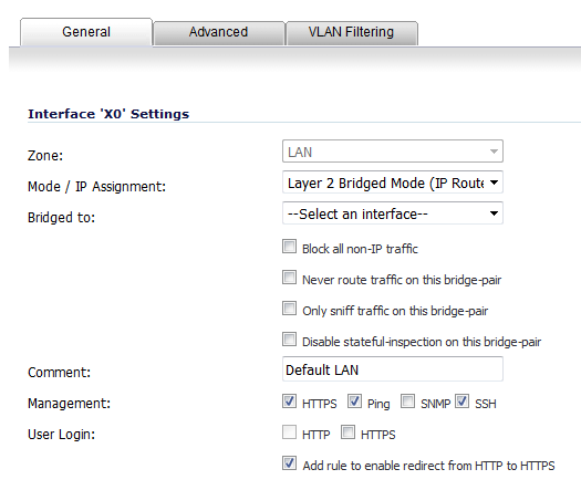
On the Edit Interface dialog, set the IP Assignment to Layer 2 Bridged Mode (IP Route Option). The options change.
|
|
4
|
|
5
|
To block all non-IP traffic on the bridged pair, select the Block all non-IP traffic checkbox. This option is not selected by default.
|
|
6
|
To prevent traffic from being routed on the bridged pair, select the Never route traffic on this bridge-pair checkbox. This option is not selected by default.
|
|
7
|
To only sniff traffic on the bridged pair, select the Only sniff traffic on this bridge-pair checkbox. This option is not selected by default.
|
|
8
|
To prevent stateful inspection on the bridged pair, select the Disable stateful-inspection on this bridge-pair checkbox. This option is not selected by default.
|
|
9
|
Ensure the interface is configured for HTTPS and SNMP so it can be managed from the DMZ by PCM+/NIM.
|
|
11
|
Click OK to save and activate the change.
|
Perimeter Security is a network scenario where the firewall is added to the perimeter for the purpose of providing security services (the network may or may not have an existing firewall between the firewall and the router). In this scenario, everything below the firewall (the Primary Bridge Interface segment) will generally be considered as having a lower level of trust than everything to the left of the firewall (the Secondary Bridge Interface segment). For that reason, it would be appropriate to use X1 (Primary WAN) as the Primary Bridge Interface.
Traffic from hosts connected to the Secondary Bridge Interface (LAN) would be permitted outbound through the firewall to their gateways (VLAN interfaces on the L3 switch and then through the router), while traffic from the Primary Bridge Interface (WAN) would, by default, not be permitted inbound.
If there are public servers, for example, a mail and Web server, on the Secondary Bridge Interface (LAN) segment, an Access Rule allowing WAN->LAN traffic for the appropriate IP addresses and services could be added to allow inbound traffic to those servers.
In this network scenario, the firewall acts as the perimeter security device while simultaneously providing L2 Bridge security between the workstation and server segments of the network without having to readdress any of the workstation or servers.
This typical inter-departmental Mixed Mode topology deployment demonstrates how the firewall can simultaneously Bridge and route/NAT. Traffic to/from the Primary Bridge Interface (Server) segment from/to the Secondary Bridge Interface (Workstation) segment will pass through the L2 Bridge.
As both interfaces of the Bridge-Pair are assigned to a Trusted (LAN) zone, the following applies:
|
•
|
The DHCP server would be in the DMZ. DHCP requests from the Workstations would pass through the L2 Bridge to the DHCP server (192.168.0.100), but the DHCP offers from the server would be dropped by the default DMZ->LAN Deny Access Rule. An Access Rule would have to be added, or the default modified, to allow this traffic from the DMZ to the LAN.
|
|
•
|
Security services directionality would be classified as Outgoing for traffic from the Workstations to the Server since the traffic would have a Trusted source zone and a Public destination zone. This might be sub-optimal since it would provide less scrutiny than the Incoming or (ideally) Trust classifications.
|
|
•
|
Security services directionality would be classified as Trust, and all signatures (Incoming, Outgoing, and Bidirectional) will be applied, providing the highest level of security to/from both segments.
|
For detailed instructions on configuring interfaces in Layer 2 Bridged Mode, see Configuring Layer 2 Bridged Mode
This method is appropriate in networks where both High Availability and Layer 2 Bridged Mode are desired. This example, shown in Figure 9, is for Dell SonicWALL Security Appliances, and assumes the use of switches with VLANs configured.
Figure 9. Internal security: Example where both High Availability and Layer 2 Bridged Mode are desired
|
•
|
Using multiple tag ports: As shown in Figure 9, two tag (802.1q) ports were created for VLAN 100 on both the Edge switch (ports 23 and 24) and Core switch (C24 - D24). The appliances are connected inline between these two switches. In a high-performance environment, it is usually recommended to have Link Aggregation/Port Trunking, Dynamic LACP, or even a completely separate link designated for such a deployment (using OSPF), and the fault tolerance of each of the switches must be considered. Consult your switch documentation for more information.
|
|
1
|
On the Firewall > Access Rules page, click the Configure icon for the intersection of WAN to LAN traffic.
|
|
2
|
Click the Configure icon next to the default rule that implicitly blocks uninitiated traffic from the WAN to the LAN.
|
|
3
|
|
4
|
Click OK.
|
In this scenario, the WAN interface is used for the following:
On the Network > Interfaces page of the SonicOS management interface, click the Configure icon for the WAN interface, and then assign it an address that can access the Internet so that the appliance can obtain signature updates and communicate with NTP.
The gateway and internal/external DNS address settings will match those of your SSL VPN appliance:
|
•
|
IP address: This must match the address for the internal interface on the SSL VPN appliance.
|
|
•
|
Subnet Mask, Default Gateway, and DNS Server(s): Make these addresses match your SSL VPN appliance settings.
|
For the Management setting, select the HTTPS and Ping check boxes. Click OK to save and activate the changes.
|
1
|
Navigate to the Network > Interfaces page.
|
|
2
|
|
3
|
|
4
|
If you also need to pass VLAN tagged traffic, supported on firewalls, click the VLAN Filtering tab and add all of the VLANs that need to be passed.
|
|
5
|
Click OK to save and activate the change. You may be automatically disconnected from the network security appliance’s management interface. You can now disconnect your management laptop or desktop from the appliance’s X0 interface and power the appliance off before physically connecting it to your network.
|
If your SSL VPN appliance is in two-port mode behind a third-party firewall, it is dual-homed.
|
1
|
|
1
|
Make sure that all security services for the Dell SonicWALL Security Appliance are enabled. See Licensing Services and Activating Security Services on Each Zone .
SonicWALL Content Filtering Service must be disabled before the device is deployed in conjunction with a Dell SMA SSL VPN appliance. On the Network > Zones page, click Configure next to the LAN (X0) zone, clear the Enforce Content Filtering Service checkbox and then click OK.
If you have not yet changed the administrative password on the Dell SonicWALL Security Appliance, you can do so on the System > Administration page.
To test access to your network from an external client, connect to the SSL VPN appliance and log in. Once connected, attempt to access to your internal network resources. If there are any problems, review your configuration and see Configuring the Common Settings for L2 Bridged Mode Deployments .