The following sections describe how to configure the types of SonicPoint profiles:
For a SonicPoint overview, see About SonicPoints .
|
1
|
Navigate to SonicPoint > SonicPoints page.
|
|
•
|
SonicPoint AC profile, click Add SonicPoint ACe/ACi/N2 Profile.
|
|
•
|
SonicPoint NDR profile, click Add SonicPoint NDR Profile.
|
|
•
|
To edit an existing AC or NDA profile, click the Configure icon on the same row as the profile you want to edit.
|
The Add/Edit SonicPoint … Profile dialog appears. The two dialogs are the same except if you are editing an existing profile, the existing settings are displayed.
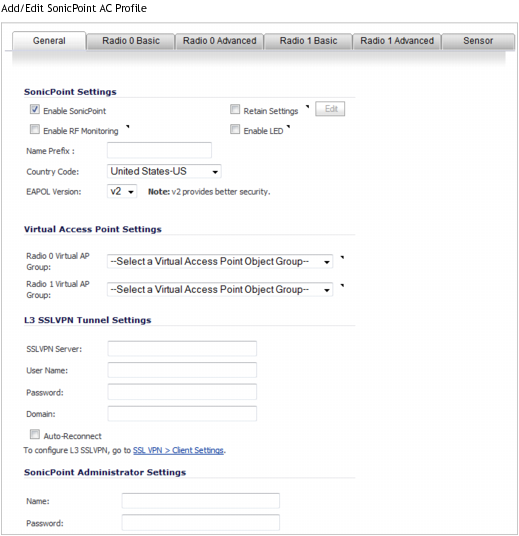

In the General tab, configure the desired settings:


|
1
|
Check Enable SonicPoint to enable each SonicPoint automatically when it is provisioned with this profile. This option is selected by default.
|
|
2
|
Optionally, check Retain Settings to have the SonicPoints provisioned by this profile retain portions of their customized settings after they are deleted and resynchronized. The settings are retained until the SonicPoint is rebooted. This option is not selected by default.
|
If you select this option, Edit becomes active. To specify the settings to retain:
|
a
|

|
•
|
Click Retain All Settings; all the other options become dimmed.
|
|
c
|
Click OK.
|
|
3
|
Optionally, check Enable RF Monitoring to enable wireless RF Threat Real Time Monitoring and Management. This option is not selected by default. For more information about RF monitoring, see SonicPoint > RF Monitoring .
|
|
•
|
SonicPoint AC profile, optionally, check Enable LED to enable/disable SonicPoint AC LEDs. This option is not selected by default (LEDs are disabled).
|
|
5
|
Enter a prefix for the names of all SonicPoints connected to this zone in the Name Prefix field. This prefix assists in identifying SonicPoint on a zone. When each SonicPoint is provisioned, it is given a name that consists of the name prefix and a unique number, for example: SonicPoint AC 126008 or SonicPoint NDR 126009.
|
|
6
|
Select the country where you are operating the SonicPoints from the Country Code drop-down menu. The country code determines under which regulatory domain the radio operation falls.
|
|
7
|
From the EAPOL Version drop-down menu, select the version of EAPoL (Extensible Authentication Protocol over LAN) to use: v1 or v2. The default is v2, which provides better security.
|

|
1
|
Optionally, select an 802.11n Virtual Access Point (VAP) group to assign these SonicPoints to a VAP from the Radio 0 Basic Virtual AP Group and Radio 1 Basic Virtual AP Group drop-down menus. The drop-down menus allow you to create a new VAP group. For more information on VAPs, see SonicPoint > Virtual Access Point .
|
|
NOTE: Selecting a VAP group for Radio 0 and/or Radio 1 affects options on the appropriate Radio 0/1 Basic tabs.
|
|
1
|
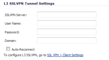
In the SSL VPN Server field, enter the IP address of the SSL VPN server.
|
|
2
|
In the User Name field, enter the User Name of the SSL VPN server.
|
|
3
|
In the Password field, enter the Password for the SSL VPN server.
|
|
4
|
In the Domain field, enter the domain that the SSL VPN server is located in.
|
|
5
|
Optionally, click Auto-Reconnect for the SonicPoint to auto-reconnect to the SSL VPN server. This option is not selected by default.
|
|
NOTE: To configure L3 SSL VPN, click the link to SSL VPN > Client Settings. For information about Layer 3 SSL VPN, refer to SonicPoint Layer 3 Management and SSL VPN > Client Settings .
|

|
1
|
In the Name field, enter the user name for the network administrator.
|
|
2
|
In the Password field, enter the password for the network administrator.
|
|
NOTE: The available options on these tabs depend on whether a VAP group was selected in the Virtual Access Point Settings on the General tab.
|


The Radio 0 Basic and Radio 1 Basic tabs are similar and have only a few differences that are noted in the steps.
|
NOTE: The sections and options displayed on the Radio 0/1 Basic tabs change depending on whether you selected a VAP group in the Radio 0/1 Virtual AP Group drop-down menus on the General tab and the mode you select in the Mode drop-down menu. These choices apply only to the radio for which they were selected, that is, if you select a VAP for Radio 0 but not Radio 1, Radio 1 is not affected and vice versa.
|
|
1
|
|
1
|
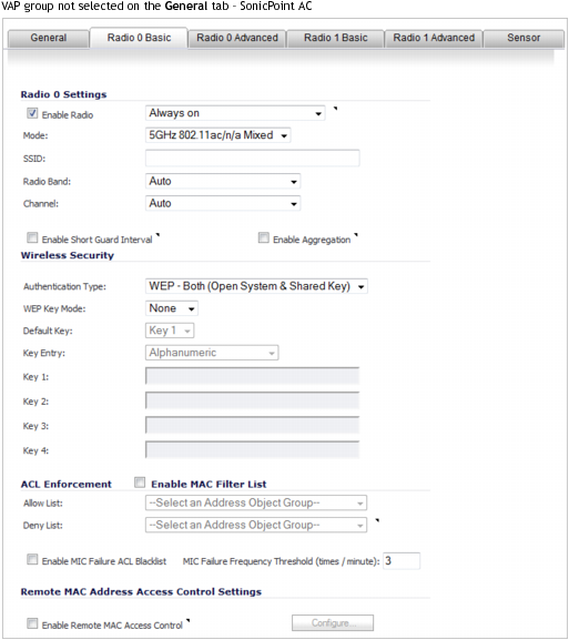
Check Enable Radio to enable the 802.11ac radio bands automatically on all SonicPoint ACs provisioned with this profile. This option is selected by default.
|
|
•
|
From the Enable Radio drop-down menu, select a schedule for when the 802.11n radio is on or create a new schedule; default is Always on. You can create a new schedule by selecting Create new schedule to display the Add Schedule menu.
|
|
2
|
Select your preferred radio mode from the Mode drop-down menu:
|
|
Select this mode if only 802.11a clients access your wireless network. |
||
|
TIP: For 802.11n clients only, for optimal throughput speed solely, Dell SonicWALL recommends the 802.11n Only radio mode. Use the 802.11n/b/g Mixed radio mode for multiple wireless client authentication compatibility.
For optimal throughput speed solely for 802.11ac clients, SonicWALL recommends the 802.11ac Only radio mode. Use the 802.11ac/n/a Mixed radio mode for multiple wireless client authentication compatibility. |
|
NOTE: The available 802.11n Radio 0/1 Settings options change depending on the mode selected. If the wireless radio is configured for a mode that:
|
|
•
|
SonicPoint NDR with VAP selected on the General tab, optionally, select Enable DFS Channels to enable the use of Dynamic Frequency Selection (DFS) that allows wireless devices to share the same spectrum with existing radar systems within the 5GHz band.
|
|
TIP: If you select this option, choose either Standard - 2MHz Channel or Wide - 40MHz Channel as the Radio Band. The Primary Channel and Standard Channel drop-down menus then display a choice of available sensitive channels.
|
|
NOTE: This option only appears on the 802.11n Radio 0 tab as the 802.11n Radio 1 does not have a wireless speed connection mode of at least 5GHz.
|
|
•
|
SonicPoint without a VAP group, in the SSID field, enter a recognizable string for the SSID of each SonicPoint using this profile. This is the name that appears in clients’ lists of available wireless connections.
|
|
5
|
If the Mode you selected was:
|
|
•
|
|
•
|
Any other mode, select a radio band from the Radio Band drop-down menu:
|
|
•
|
Auto - Allows the appliance to automatically detect and set the optimal channel for wireless operation based on signal strength and integrity. Both the Primary Channel and Secondary Channel are set to Auto also. This is the default setting.
|
|
•
|
Standard - 20MHz Channel—Specifies that Radio 0 uses only the standard 20MHz channel. When this option is selected, the Standard Channel drop-down menu is displayed instead of the Primary Channel and Secondary Channel options.
|
|
•
|
Wide - 40MHz Channel—Available only when 5GHz 802.11ac/n/a or 5GHz 802.11ac is selected for the Radio Band, specifies that Radio 0 uses only the wide 80MHz channel. When this option is selected, only the Channel drop-down menu is active
|
|
6
|
Select a channel from the Standard/Primary Channel drop-down menu. Depending on the Mode and Radio Band selections, a Secondary Channel drop-down menu displays.
|
|
•
|
Auto - Allows the appliance to automatically detect and set the optimal channel for wireless operation based on signal strength and integrity. This is the default setting for the Standard/Primary Channels. The Secondary Channel Is set to Auto regardless of the setting of Primary Channel.
|
|
•
|
Optionally, you can select a single channel within the range of your regulatory domain. Selecting a specific a channel can also help with avoiding interference with other wireless networks in the area. The available channels depend on which Radio you are configuring; see Figure 23. If you select Wide – 40 MHz Channel for Radio Band, a Secondary Channel displays and is selected automatically by the selection of the Primary Channel.
|
|
Radio 0: Channel/Primary Channel 1 |
Radio 1: Secondary Channel is set automatically to: 2 |
|
|
Channel 165 (5825MHz) 3 |
||
|
7
|
If, from the Radio Band drop-down menu, you selected:
|
|
•
|
5GHz 802.11a Only or 2.4GHz 802.11g Only, and are configuring:
|
|
8
|
Enable Short Guard Interval—Specifies the short guard interval of 400ns (as opposed to the standard guard interval of 800ns).
|
The 802.11n standard specifies two guard intervals: 400ns (short) and 800ns (long).
|
TIP: The Enable Short Guard Interval and Enable Aggregation options can slightly improve throughput. They both function best in optimum network conditions where users have strong signals with little interference. In networks that experience less than optimum conditions (interference, weak signals, and so on), these options could introduce transmission errors that eliminate any efficiency gains in throughput.
|
|
9
|
Select Enable Aggregation to enable 802.11n and 802.11ac frame aggregation that combines multiple data frames in a single transmission to reduce overhead and increase throughput.
|
|
•
|
SonicPoint NDR, optionally select Enable MIMO. This option is selected by default.
|
The Enable MIMO option enables/disables MIMO (multiple-input multiple output). Enabling this option increases 802.11n throughput by using multiple-input/multiple-output antennas. This option is enabled by default for all 802.11n modes and is dimmed to ensure it is not disabled. The option is activated and selected by default if 5GHz 802.11a Only or 2.4GHz 802.11g Only mode is selected.
|
NOTE: If a VAP was selected in the Virtual Access Point Settings section of the General tab, this section is not available. Instead, the Virtual Access Point Encryption Settings section is displayed. Go to Virtual Access Point Encryption Settings .
|

The Wireless Security sections of both Radio 0 Basic and Radio 1 Basic tabs are the same as for the SonicPoint N 802.11n Radio tab. For how to configure the Wireless Security settings, see Wireless Security .
|
NOTE: This section displays only if a VAP was selected from the Radio 0 Basic/1 Virtual AP Group drop-down menus in the Virtual Access Point Settings section of the General tab.
|

The Virtual Access Point Encryption Settings section of both Radio 0 Basic and Radio 1 Basic tabs are the same as for the SonicPoint N 802.11n Radio tab. For how to configure the Virtual Access Point Encryption Settings settings, see Virtual Access Point Encryption Settings .

The ACL Enforcement section of both Radio 0 Basic and Radio 1 Basic tabs are the same as for the SonicPoint N 802.11n Radio tab. For how to configure the ACL Enforcement settings, see ACL Enforcement .
|
NOTE: If a VAP was selected in the 802.11n Radio Virtual AP Group drop-down menu on the Settings tab, this section is not available; go to Radio 0/Radio 1 Advanced Tabs .
|

The Remote MAC Address Access Control Settings section of both 802.11n Radio 0 and 802.11n Radio 1 tabs are the same as for the SonicPoint N 802.11n Radio tab.
|
IMPORTANT: You cannot enable the Remote MAC address access control option at the same time that IEEE 802.11i EAP is enabled. If you try to do so, you could receive the following error message:
|
|
1
|
Select Enable Remote MAC Access Control. This option enforces radio wireless access control according to the MAC-based authentication policy in the remote Radius server. The Configure button becomes active.
|
|
2
|

|
4
|
Click OK.
|


The Radio 1 Advanced tab has the same options as the Radio 0 Advanced tab plus other options. The tabs for SonicPoint AC and SonicPoint NDR are quite similar. Differences are noted in the procedure.
|
1
|
Click the Radio 0/1 Advanced tab.
|
|
2
|
|
•
|
|
•
|
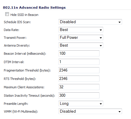
Did not select a VAP on the Settings tab, optionally, select Hide SSID in Beacon to have the SSID send null SSID beacons in place of advertising the wireless SSID name. Sending null SSID beacons forces wireless clients to know the SSID to connect. This option is unchecked by default.
|
|
3
|
From the Schedule IDS Scan drop-down menu, select a schedule for the IDS (Intrusion Detection Service) scan. Select a time when there are fewer demands on the wireless network to minimize the inconvenience of dropped wireless connections. You can create your own schedule by selecting Create new schedule or disable the feature by selecting Disabled, the default.
|
|
4
|
From the Data Rate drop-down menu, select the speed at which the data is transmitted and received. Best (default) automatically selects the best rate available in your area given interference and other factors.
|
|
5
|
From the Transmit Power drop-down menu, select the transmission power. Transmission power effects the range of the SonicPoint.
|
|
•
|
Full Power (default)
|
|
•
|
|
•
|
SonicPoint NDR, from the Antenna Diversity drop-down menu, select Best, the default. The Antenna Diversity setting determines which antenna the SonicPoint uses to send and receive data. When Best is selected, the SonicPoint automatically selects the antenna with the strongest, clearest signal.
|
|
7
|
In the Beacon Interval (milliseconds) field, enter the number of milliseconds between sending wireless SSID beacons. The minimum interval is 100 milliseconds, the maximum is 1000 milliseconds, and the default is 100 milliseconds.
|
|
8
|
In the DTIM Interval field, enter the DTIM interval in milliseconds. The minimum number of frames is 1, the maximum is 255, and the default is 1.
|
For 802.11 power-save mode clients of incoming multicast packets, the DTIM interval specifies the number of beacon frames to wait before sending a DTIM (Delivery Traffic Indication Message).
|
•
|
SonicPoint NDR, in the Fragmentation Threshold (bytes) field, enter the number of bytes of fragmented data you want the network to allow. The fragmentation threshold limits the maximum frame size. Limiting frame size reduces the time required to transmit the frame and, therefore, reduces the probability that the frame will be corrupted (at the cost of more data overhead). Fragmented wireless frames increase reliability and throughput in areas with RF interference or poor wireless coverage. Lower threshold numbers produce more fragments. The minimum is 256 bytes, the maximum is 2346 bytes, and the default is 2346 bytes.
|
|
10
|
In the RTS Threshold (bytes) field, enter the threshold for a packet size, in bytes, at which a request to send (RTS) is sent before packet transmission. Sending an RTS ensures that wireless collisions do not take place in situations where clients are in range of the same access point, but might not be in range of each other. The minimum threshold is 256 bytes, the maximum is 2346 bytes, and the default is 2346 byes.
|
|
11
|
In the Maximum Client Associations field, enter the maximum number of clients you want each SonicPoint using this profile to support on this radio at one time. The minimum number of clients is 1, the maximum number is 128, and the default number is 32.
|
|
12
|
In the Station Inactivity Timeout (seconds) field, enter the maximum length of wireless client inactivity before Access Points age out the wireless client, in seconds. The minimum period is 60 seconds, the maximum is 36000 seconds, and the default is 300 seconds.
|
|
•
|
Radio 0 Advanced settings, go to Step 17.
|
|
•
|
Radio 1 Advanced tab settings, go to Step 14.
|
|
14
|
Select a preamble length from the Preamble Length drop-down menu:
|
|
•
|
Long (default)
|
|
•
|
|
15
|
Select a protection mode from the Protection Mode drop-down menu:
|
|
•
|
1 Mbps (default)
|
|
•
|
|
•
|
|
•
|
|
16
|
Select a protection type from the Protection Type drop-down menu:
|
|
•
|
CTS-only (default)
|
|
•
|
|
17
|
Optionally, to allow clients to disassociate and reassociate more quickly, select the Enable Short Slot Time checkbox. Specifying this option increases throughput on the 802.11n/g wireless band by shortening the time an access point waits before relaying packets to the LAN. This setting is not selected by default.
|
|
18
|
Optionally, if you are using Turbo G mode and, therefore, are not allowing 802.11b clients to connect, select the Do(es) not allow 802.11b Client to Connect checkbox. Specifying this option limits wireless connections to 802.11g and 802.11n clients only. This setting is not selected by default.
|
|
19
|
From the WMM (Wi-Fi Multimedia) drop-down menu, select whether a WMM profile is to be associated with this profile:
|
|
•
|
Disabled (default)
|
|
•
|
Create new WMM profile. If you select Create new WMM profile, the Add Wlan WMM Profile dialog displays. For information about configuring a WMM profile, see Configuring Wi-Fi Multimedia Parameters .
|
|
20
|
Optionally, select Enable Green AP to allow the SonicPoint ACe/ACi/N2 radio to go into sleep mode. This saves power when no clients are actively connected to the SonicPoint. The SonicPoint immediately goes into full power mode when any client attempts to connect to it. Green AP can be set on each radio independently, Radio 0 (5GHz) and Radio 1 (2.4GHz).
|
|
•
|
Radio 0 Advanced, repeat the procedure for Radio 1 Advanced.
|
|
•
|
Radio 1 Advanced for:
|
|
22
|
In the Green AP Timeout(s) field, enter the transition time, in seconds, that the access point waits while it has no active connections before it goes into sleep mode, that is, the time between power-save off to power-save on. The transition values can range from 20 seconds to 65535 seconds with a default value of 20 seconds.
|

In the Sensor tab, enable or disable Wireless Intrusion Detection and Prevention (WIDP) mode.
|
1
|
Select Enable WIDF sensor to have the SonicPoint operate as a dedicated WIDP sensor. This option is not selected by default.
|
|
2
|
From the drop-down menu, select the schedule for when the SonicPoint operates as a WIDP sensor or select Create new schedule… to specify a different time; default is Always on.
|
For a SonicPoint overview, see Understanding SonicPoints .
|
1
|
Navigate to SonicPoint > SonicPoints page.
|
|
•
|
To add a new SonicPoint N profile, click Add SonicPoint N Profile.
|
|
•
|
To edit an existing SonicPoint N profile, click the Configure icon on the same row as the profile you want to edit.
|
The Add/Edit SonicPointN Profile dialog appears. The two dialogs are the same except if you are editing an existing profile, the existing settings are displayed.

The Settings tab has these sections:

|
1
|
To automatically enable each SonicPoint when it is provisioned with this profile, select Enable SonicPoint. This option is selected by default.
|
|
2
|
Optionally, check Retain Settings to have the SonicPoint Ns provisioned by this profile retain customized settings until system restart or reboot. This option is not selected by default.
|
If you select this option, Edit becomes active. To specify the settings to retain:
|
a
|
|
•
|
Click Retain All Settings; all the other options are dimmed.
|
|
c
|
Click OK.
|
|
3
|
Optionally, check Enable RF Monitoring to enable wireless RF Threat Real Time Monitoring and Management. This option is not selected by default.
|
|
4
|
Optionally, check Enable LED (Ni/Ne) to turn SonicPointN LEDs on/off.
|
|
5
|
Enter a prefix for the names of all SonicPointNs connected to this zone in the Name Prefix field. This prefix assists in identifying SonicPoints on a zone. When each SonicPointN is provisioned, it is given a name that consists of the name prefix and a unique number, for example: MySonicPoint 126008.
|
|
6
|
Select the country where you are operating the SonicPoint Ns from the Country Code drop-down menu. The country code determines which regulatory domain the radio operation falls under.
|
|
7
|
From the EAPOL Version drop-down menu, select the version of EAPoL (Extensible Authentication Protocol over LAN) to use: v1 or v2. The default is v2, which provides better security than v2.
|

|
1
|
Optionally, from the 802.11n Radio Virtual AP Group drop-down menu, select an 802.11n Virtual Access Point (VAP) group to assign these SonicPoint Ns to a VAP. This drop-down menu allows you to create a new VAP group. For more information on VAPs, see SonicPoint > Virtual Access Point .
|
|
1
|
In the SSL VPN Server field, enter the IP address of the SSL VPN server.
|
|
2
|
In the User Name field, enter the user name of the SSL VPN server.
|
|
3
|
In the Password field, enter the password for the SSL VPN server.
|
|
4
|
In the Domain field, enter the domain that the SSL VPN server is located in.
|
|
5
|
Click Auto-Reconnect for the SonicPoint to auto-reconnect to the SSL VPN server.
|
|
NOTE: To configure L3 SSL VPN, click the link to SSL VPN > Client Settings. For information about Layer 3 SSL VPN, refer to SonicPoint Layer 3 Management and SSL VPN > Client Settings .
|
|
1
|
In the Name field, enter the user name for the network administrator.
|
|
2
|
In the Password field, enter the password for the network administrator.
|
|
NOTE: The sections and options displayed on the 802.11n Radio tab change depending on whether you selected a VAP group in the 802.11n Radio Virtual AP Group drop-down menu on the Settings tab and the mode you selected from the Mode drop-down menu.
|


|
1
|
Click the 802.11n Radio tab.
|

|
1
|
Check Enable Radio to automatically enable the 802.11n radio bands on all SonicPoints provisioned with this profile. This option is selected by default.
|
|
•
|
From the Enable Radio drop-down menu, select the schedule for when the802.11n radio is on. The default schedule is Always On. You can create a new schedule by selecting Create new schedule.
|
|
2
|
Select your preferred radio mode from the Mode drop-down menu. The wireless security appliance supports the modes shown in Table 72.
|
|
NOTE: The available 801.11n Radio Settings options change depending on the mode selected. If the wireless radio is configured for a mode that:
|
|
TIP: For optimal throughput speed solely for 802.11n clients, SonicWALL recommends the 802.11n Only radio mode. Use the 802.11n/b/g Mixed radio mode for multiple wireless client authentication compatibility.
|
|
Select this mode if only 802.11a clients access your wireless network. |
||
|
Select this mode if only 802.11ac clients access your wireless network. |
|
3
|
If you chose 5GHz 802.11n Only, 5GHz 802.11a/n Mixed, or 5GHz 802.11a Only for Mode, optionally check Enable DFS Channels. Enabling Dynamic Frequency Selection (DFS) allows wireless devices to share spectrum with existing radar systems in the 5GHz band. This setting is not selected by default.
|
|
4
|
If you did not specify a VAP group on the Settings tab, in the SSID field, enter a recognizable string for the SSID of each SonicPoint using this profile. This is the name that appears in clients’ lists of available wireless connections.
|
|
6
|
Only for 802.11a/g: Select the channel for the radio from the Channel drop-down menu:
|
|
•
|
Auto - Allows the appliance to automatically detect and set the optimal channel for wireless operation based on signal strength and integrity. This is the default setting. Use Auto unless you have a specific reason to use or avoid specific channels.
|
|
7
|
|
8
|
For 802.11n only or 802.11n mixed: From the Radio Band drop-down menu, select the band for the 802.11n radio:
|
|
•
|
Auto - Allows the appliance to automatically detect and set the optimal channel for wireless operation based on signal strength and integrity. This is the default setting.
|
|
•
|
|
•
|
Standard - 20 MHz Channel - Specifies that the 802.11n radio will use only the standard 20 MHz channel. When this option is selected, the Channel drop-down menu is displayed instead of the Primary Channel and Secondary Channel drop-down menus.
|
|
•
|
Channel - By default, this is set to Auto, which allows the appliance to set the optimal channel based on signal strength and integrity. Optionally, you can select a single channel within the range of your regulatory domain. Selecting a specific a channel can also help with avoiding interference with other wireless networks in the area. The available channels are the same as for 802.11g in Step 6.
|
|
•
|
Wide - 40 MHz Channel - Specifies that the 802.11n radio will use only the wide 40 MHz channel. When this option is selected, the Primary Channel and Secondary Channel drop-down menus are displayed:
|
|
•
|
Primary Channel - By default, this is set to Auto. Optionally, you can specify a specific primary channel. The available channels are the same as for 802.11a in Step 6
|
|
•
|
Secondary Channel - The configuration of this drop-down menu is set to Auto regardless of the primary channel setting.
|
|
9
|
Optionally, select the Enable Short Guard Interval checkbox to specify a short guard interval of 400ns as opposed to the standard guard interval of 800ns. This setting is not selected by default.
|
|
10
|
|
TIP: The Enable Short Guard Interval and Enable aggregation options can slightly improve throughput. They both function best in optimum network conditions where users have strong signals with little interference. In networks that experience less than optimum conditions (interference, weak signals, and so on), these options may introduce transmission errors that eliminate any efficiency gains in throughput.
|
|
11
|
Select Enable MIMO to enable MIMO (multiple-input multiple output). Enabling this option increases 802.11n throughput by using multiple-input/multiple-output antennas.
|
This option is enabled by default for all 802.11n modes and is dimmed to ensure it is not disabled. The option is activated and selected by default if 5GHz 802.11a Only or 2.4GHz 802.11g Only mode is selected.
|
12
|
|
•
|
Selected a VAP from the 802.11n Radio Virtual AP Group drop-down menu in the Virtual Access Point Settings section of the Settings tab, go to Virtual Access Point Encryption Settings .
|
|
NOTE: If a VAP was selected in the 802.11n Radio Virtual AP Group drop-down menu on the Settings tab, this section is not available. Instead, the Virtual Access Point Encryption Settings section is displayed. Go to Virtual Access Point Encryption Settings .
|
|
1
|
In the Wireless Security section, select the method of authentication for your wireless network from the Authentication Type drop-down menu:
|
|
WEP 1 |
WPA 2 |
|
|
WEP - Both (Open System & Shared Key) – default |
||
|
WEP - Open System 3 |
||
WEP (Wired Equivalent Privacy) is a standard for Wi-Fi wireless network security.
|
1
|
Select the size of the encryption key from the WEP Key Mode drop-down menu:
|
|
•
|
None – Default for WEP - Both (Open System & Shared Key). If selected, the rest of the options in this section remain dimmed; go to ACL Enforcement .
|
|
•
|
|
•
|
|
•
|
152 bit - default for WEP - Shared Key
|
|
2
|
From the Default Key drop-down menu, select which key is the default key, that is, the key that is tried first when trying to authenticate a user:
|
|
•
|
Key 1 (default)
|
|
•
|
|
•
|
|
•
|
|
3
|
From the Key Entry drop-down menu, select whether the key is:
|
|
•
|
Alphanumeric (default)
|
|
4
|
In the Key 1 - Key 4 fields, enter up to four possible WEP encryptions keys used when transferring encrypted wireless traffic. Enter the most likely to be used in the field you selected as the default key:
|
|
NOTE: The length of each key is based on the selected key type (alphanumeric or hexadecimal) and WEP strength (WEP Key Mode): 64, 128, or 152 bits.
|
|
•
|
Key 1: First static WEP key associated with the key index.
|
|
•
|
Key 2: Second static WEP key associated with the key index.
|
|
•
|
Key 3: Third static WEP key associated with the key index.
|
|
•
|
Key 4: Fourth static WEP key associated with the key index.
|

|
1
|
From the Cipher Type drop-down menu, select the cipher to encrypt your wireless data:
|
|
•
|
AES (newer, more secure; default): AES (Advanced Encryption Standard) is a set of ciphers designed to prevent attacks on wireless networks. AES is available in block ciphers of either 128, 192 or 256 bits depending on the hardware you intend to use with it. In the networking field, AES is considered to be among the most secure of all commonly installed encryption packages.
|
|
•
|
TKIP (older, more compatible): TKIP (Temporary Key Integrity Protocol) is not actually a cipher, but a set of security algorithms meant to improve the overall safety of WEP (wired equivalent privacy networks). WEP is widely known to have a host of serious security vulnerabilities. TKIP adds a few extra layers of protection to WEP.
|
|
•
|
Auto: the appliance chooses the cipher type automatically.
|
|
2
|
In the Group Key Interval (seconds) field, enter the period for which a Group Key is valid, that is, the time interval before the encryption key is changed automatically for added security. The default value is 86400 seconds (24 hours). Setting too low of a value can cause connection issues.
|
|
3
|
If, from the Authentication Type drop-down menu, you selected:
|
|
4
|
For PSK authentication types only, in the Passphrase field, enter the passphrase your network users must enter to gain network access.
|
|
NOTE: This option displays only if you configure WPA-PSK, WPA2-PSK, or WPA2-AUTO-PSK for your authentication type.
|
|
5
|
|
NOTE: This option displays only if you selected WPA-EAP, WPA2-EAP, or WPA2-AUTO-EAP for your authentication type.
|

|
1
|

|
2
|
In the Radius Server Retries field, enter the number times, from 1 to 10, the firewall attempts to connect before it fails over to the other Radius server.
|
|
3
|
In the Retry Interval (seconds) field enter the time, from 0 to 60 seconds, to wait between retries. The default number is 0 or no wait between retries.
|
|
4
|
|
5
|
|
NOTE: This section displays only if a VAP was selected from the 802.11n Radio Virtual AP Group drop-down menu in the Virtual Access Point Settings section of the Settings tab.
|
|
1
|

|
2
|
From the Key Entry Method radio buttons, select whether the key is:
|
|
•
|
Alphanumeric (default)
|
|
3
|
From the Default Key radio buttons, select the default key that is tried first when trying to authenticate a user:
|
|
•
|
Key 1 (default)
|
|
•
|
|
•
|
|
•
|
|
4
|
In the Key 1 - Key 4 fields, enter up to four possible WEP encryptions keys to be used when transferring encrypted wireless traffic. Enter the most likely to be used in the field you selected as the default key.
|
|
•
|
Key 1: First static WEP key associated with the key index.
|
|
•
|
Key 2: Second static WEP key associated with the key index.
|
|
•
|
Key 3: Third static WEP key associated with the key index.
|
|
•
|
Key 4: Fourth static WEP key associated with the key index.
|
|
5
|
From the Key Type drop-down menus, select the size of each key:
|
|
•
|
None (default)
|
|
•
|
|
•
|
|
•
|
|
6
|
Click OK.
|
|
1
|
Check the Enable MAC Filter List checkbox to enforce Access Control by allowing or denying traffic from specific devices. By default, this option is not selected, and the Allow List and Deny List options are dimmed.
|
|
2
|
From the Allow List drop-down menu, select a MAC address group to allow traffic automatically from all devices with a MAC address in the group:
|
|
•
|
Create new Mac Address Object Group… – The Add Address Object Group dialog displays.
|

|
a
|
In the Name field, enter a friendly name for the address object group.
|
|
c
|
Click the Right Arrow button to move the selection(s) to the right column.
|
|
d
|
|
e
|
|
3
|
From the Deny List drop-down menu, select a MAC address group from the drop-down menu to automatically deny traffic from all devices with MAC address in the group.
|
|
•
|
Create new Mac Address Object Group… – The Add Address Object Group dialog displays. For configuring the address object group, see Step a.
|
|
4
|
Optionally, select Enable MIC Failure ACL Blacklist to detect WPA TKIP MIC failure floods and automatically places the problematic wireless station(s) into a blacklist to stop the attack. As wireless clients generate the TKIP countermeasures, they are also moved automatically into blacklist, so the other wireless stations within the same wireless LAN network are not affected. By default, this setting is not selected.
|
|
5
|
Enter the maximum number of MIC failures per minute in the MIC Failure Frequency Threshold field; default is 3. After the threshold is reached, the source is blacklisted.
|
|
TIP: When a source is blacklisted, it is added to the dynamically created Default SonicPoint ACL Deny Group. You can view this on the Network > Address Objects page.
|
|
6
|
|
•
|
|
•
|
|
IMPORTANT: If a VAP was selected in the 802.11n Radio Virtual AP Group drop-down menu on the Settings tab, this section is not available. Go to Advanced Tab .
If an EAP authentication type was selected in the Authentication Type drop-down menu, this message is displayed: Click OK. |
|
1
|
Check the Enable Remote MAC Access Control checkbox to enforce radio wireless access control based on MAC-based authentication policy in a remote Radius server.
|
|
2
|

|
3
|
For the procedure in configuring the settings on the SonicPoint Radius Server Global Settings dialog, see Remote MAC Address Access Control Settings .
|
|
4
|
Click OK.
|
In the Advanced tab, configure the performance settings for the 802.11n radio. For most 802.11n advanced options, the default settings give optimum performance.
|
1
|
Click the Advanced tab.
|
|
2
|
|
•
|
|
•
|
Did not select a VAP on the Settings tab, optionally select Hide SSID in Beacon to have the SSID send null SSID beacons in place of advertising the wireless SSID name. Sending null SSID beacons forces wireless clients to know the SSID to connect. This option is unchecked by default.
|
|
3
|
From the Schedule IDS Scan drop-down menu, select a schedule for the IDS (Intrusion Detection Service) scan. Select a time when there are fewer demands on the wireless network to schedule an IDS scan to minimize the inconvenience of dropped wireless connections. You can create your own schedule by selecting Create new schedule or disable the feature by selecting Disabled (default).
|
|
4
|
From the Data Rate: drop-down menu, select the speed at which the data is transmitted and received.
|
|
Best (default) |
||||
Best automatically selects the best rate available in your area given interference and other factors. Best is the default and is the only choice if you selected a VAP on the Settings tab.
|
5
|
From the Transmit Power drop-down menu, select the transmission power, which affects the range of the SonicPoint:
|
|
•
|
Full Power (default)
|
|
•
|
|
6
|
From the Antenna Diversity drop-down menu, select Best, the default. The Antenna Diversity setting determines which antenna the SonicPoint uses to send and receive data. When Best is selected, the SonicPoint automatically selects the antenna with the strongest, clearest signal.
|
|
7
|
In the Beacon Interval (milliseconds) field, enter the number of milliseconds between sending out wireless SSID beacons. This interval represents the amount of time between beacon transmissions. Before a station enters power-save mode, the station needs the beacon interval to know when to wake up to receive the beacon (and learn whether there are buffered frames at the access point).
|
The minimum interval is 20 milliseconds, the maximum is 1000, milliseconds, and the default is 100 milliseconds.
|
8
|
In the DTIM Interval field, enter the interval, in milliseconds, between the sending of Delivery Traffic Indication Messages (DTIMs) in the beacon. This interval is the maximum number of beacon cycles before unacknowledged network broadcasts are flushed. When using wireless clients that use power management features to sleep, the client must revive at least once during the DTIM period to receive broadcasts. 802.11 power-save mode clients are alerted of incoming multicast packets.
|
The minimum interval is 1 millisecond, the maximum is 255 milliseconds, and the default is 1 millisecond.
|
9
|
In the Fragmentation Threshold (bytes) field, enter the number of bytes of fragmented data you want the network to allow. The fragmentation threshold limits the maximum frame size. This reduces the time required to transmit the frame, and therefore reduces the probability that the frame will be corrupted (at the cost of more data overhead). Fragmented wireless frames increase reliability and throughput in areas with RF interference or poor wireless coverage. Lower threshold numbers produce more fragments.
|
The minimum is 256 bytes, the maximum is 2346 bytes, and the default is 2346 bytes.
|
10
|
In the RTS Threshold (bytes) field, enter the number of bytes of the Request to Send (RTS) threshold. The RTS threshold specifies the frame size the transmitter must use. Fragmented wireless frames increase reliability and throughput in areas with RF interference or poor wireless coverage. Wireless clients transmitting frames larger than this threshold must issue Request to Send (RTS) and wait for the AP to respond with Clear to Send (CTS). This option also not only can be used to avoid hidden node problems, but also helps prevent mid-air collisions for wireless clients that are not within wireless peer range and cannot detect when other wireless clients are transmitting or in range of the same access point, but may not in range of each other.
|
The minimum value is 256 bytes, the maximum is 2346 bytes, and the default is 2346 bytes. The default value used by many vendors is 2346 bytes. Lower threshold numbers produce more fragments.
|
11
|
In the Maximum Client Associations field, enter the maximum number of clients you want each SonicPoint using this profile to support on this radio at one time. The minimum number is 1 client, the maximum is 128 clients, and the default is 32 clients.
|
|
12
|
In the Station Inactivity Timeout (seconds) field, enter the maximum length of wireless client inactivity, in seconds, before access points age out the wireless client. The minimum period is 60 seconds, the maximum is 36000 seconds, and the default number is 300 seconds.
|
|
13
|
|
•
|
|
•
|
Selected a VAP on the Settings tab, from the Preamble Length drop-down menu, select the length of the preamble—the initial wireless communication sent when associating with a wireless host: Long or Short.
|
|
14
|
From the WMM (Wi-Fi Multimedia) drop-down menu, select whether a WMM profile is associated with this profile:
|
|
•
|
Disabled (default)
|
|
•
|
Create new WMM profile. The Add Wlan WMM Profile window displays. For information about configuring a WMM profile, see Configuring Wi-Fi Multimedia Parameters .
|

In the Sensor tab, you enable or disable Wireless Intrusion Detection and Prevention (WIDP) mode.
|
1
|
Check the Enable WIDF checkbox to have the SonicPoint N operate as a dedicated WIDP sensor.
|
|
•
|
From the drop-down menu, select the schedule for when the SonicPoint N operates as a WIDP sensor or select Create new schedule… to specify a different time; default is Always on.
|
|
2
|
Click OK.
|