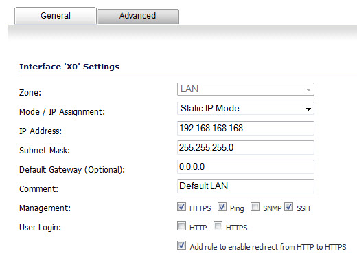
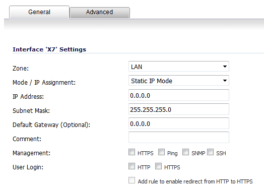
Static means that you assign a fixed IP address to the interface.
|
1
|
On the Network > Interfaces page, click the Edit icon in the Configure column for the Interface you want to configure. The Edit Interface dialog displays.
|
|
2
|
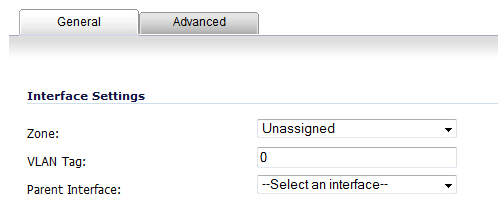
Select a zone to assign to the interface from the Zone drop-down menu:
|
|
•
|
|
•
|
|
•
|
|
•
|
|
•
|
Create new zone – The Add Zone dialog is displayed. See Network > Zones for instructions on adding a zone.
|
|
3
|
Select Static (WAN) or Static IP Mode (LAN) from the Mode / IP Assignment drop-down menu. This is the default mode.
|
|
4
|
|
5
|
If configuring a WAN zone interface or the MGMT interface, type the IP address of the gateway device into the Default Gateway (Optional) field. The gateway device provides access between this interface and the external network, whether it is the Internet or a private network. A gateway is optional for DMZ or LAN zone interfaces.
|
|
6
|
|
7
|
Enter any optional comment text in the Comment field. This text is displayed in the Comment column of the Interface table.
|
|
8
|
If you want to enable remote management of the firewall from this interface, select the supported Management protocol(s): HTTPS, Ping, SNMP, and/or SSH.
|
To allow access to the WAN interface for management from another zone on the same appliance, access rules must be created. See Allowing WAN Primary IP Access from the LAN Zone for more information.
|
9
|
If you want to allow selected users with limited management rights to log in to the security appliance, select HTTP and/or HTTPS in User Login.
|
|
10
|
Click OK.
|
|
1
|
|
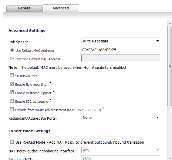
NOTE: The options available on the Advanced tab for a static interface vary depending on the selected zone.
|
|
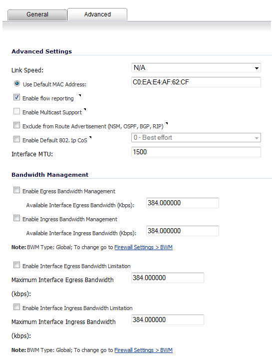
2
|
For Link Speed, Auto Negotiate is selected by default, which causes the connected devices to negotiate the speed and duplex mode of the Ethernet connection automatically. To force Ethernet speed and duplex, select one of the following options from the Link Speed drop-down menu:
|
|
3
|
Use Default MAC Address is selected by default and the default MAC address is populated in the field automatically. You can choose to override the Use Default MAC Address for the interface by selecting Override Default MAC Address and entering the MAC address in that field.
|
|
4
|
Select the Shutdown Port checkbox to temporarily take this interface offline for maintenance or other reasons. If connected, the link will go down.
|
|
If you select this option, a confirmation message is displayed:
Click OK to shut down the port.
TIP: You can shut down the interface by clicking the Enabled icon in the Enabled column for the interface. A confirmation message displays:
If you click OK, the Enabled icon turns to a Disabled icon. To enable the interface, click the Disabled icon. A confirmation message displays:
If you click OK, the Disabled icon turns to an Enabled icon. |
|
5
|
For the AppFlow feature, select the Enable flow reporting checkbox to allow flow reporting on flows created for this interface. This option is selected by default.
|
|
6
|
Optionally, select the Enable Multicast Support checkbox to allow multicast reception on this interface. This option is not selected by default.
|
|
7
|
Optionally, select the Enable Default 802.1p tagging checkbox to tag information passing through this interface with 802.1p priority information for Quality of Service (QoS) management. This option is not selected by default.
|
Packets sent through this interface are tagged with VLAN id=0 and carry 802.1p priority information. To make use of this priority information, devices connected to this interface should support priority frames. QoS management is controlled by access rules on the Firewall > Access Rules page. For information on QoS and bandwidth management, see Firewall Settings > QoS Mapping .
|
8
|
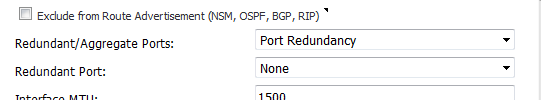
Optionally, to exclude the interface from Route Advertisement, select the Exclude from Route Advertisement (NSM, OSPF, BGP, RIP) checkbox. This option is not selected by default.
|
|
9
|
Optionally, enable Asymmetric Route Support on the interface by selecting the Enable Asymmetric Route Support checkbox. If enabled, the traffic initialized from this interface supports asymmetric routes, that is, the initial packet or response packet can pass through from other interfaces. This checkbox is not selected by default. For more information about asymmetric routing, see Asymmetric Routing In Cluster Configurations .
|
|
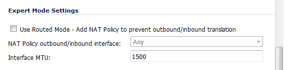
10
|
Optionally select Link Aggregation or Port Redundancy from the Redundant /Aggregate Ports drop-down menu. For more information see Configuring Link Aggregation .
|
|
11
|
Optionally select the Use Routed Mode – Add NAT Policy to prevent outbound/inbound translation checkbox. For more information about Routed Mode, see Configuring Routed Mode .
|
|
12
|
|
NOTE: Jumbo frame support must be enabled before a port can process jumbo frames, as explained in Jumbo Frame . Due to jumbo frame packet buffer size requirements, jumbo frames increase memory requirements by a factor of 4.
|
|
13
|
|
a
|
To limit outgoing traffic to a maximum bandwidth on the interface, select the Enable Interface Egress Bandwidth Limitation checkbox. This option is not selected by default.
|
|
•
|
Specify the maximum bandwidth, in kbps, in the Maximum Interface Egress Bandwidth field. The default is 384.000000 kbps.
|
|
b
|
To limit incoming traffic to a maximum bandwidth on the interface, select the Enable Interface Ingress Bandwidth Limitation checkbox. This option is not selected by default.
|
|
•
|
Specify the maximum bandwidth, in kbps, in the Maximum Interface Egress Bandwidth field. The default is 384.000000 kbps.
|
Figure 6. Routed mode configuration
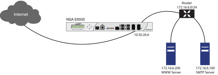
By enabling Routed Mode on the interface for the 172.16.6.0 network, NAT translations will be automatically disabled for the interface, and all inbound and outbound traffic will be routed to the WAN interface configured for the 10.50.26.0 network.
|
1
|
Navigate to the Network > Interfaces page.
|
|
2
|
|
3
|
Click on the Advanced tab.
|
|
4
|
Scroll to the Expert Mode Settings heading.
|
|
5
|
Select the Use Routed Mode - Add NAT Policy to prevent outbound\inbound translation checkbox to enable Routed Mode for the interface. This option is not selected by default. When you select it, the other two Expert Mode settings become available.
|
|
6
|
In the NAT Policy outbound/inbound interface drop-down menu, select the WAN interface that is to be used to route traffic for the interface. The default is Any.
|
|
7
|
|
8
|
Click OK.
|
Bandwidth Management (BWM) allows you to guarantee minimum bandwidth and prioritize traffic. BWM is enabled in the Firewall Settings > BWM page. By controlling the amount of bandwidth to an application or user, you can prevent a small number of applications or users from consuming all available bandwidth. Balancing the bandwidth allocated to different network traffic and then assigning priorities to traffic improves network performance.
Three types of bandwidth management can be enabled on the Firewall > BWM page:
|
•
|
Advanced—Enables you to configure maximum egress and ingress bandwidth limitations per interface, by configuring bandwidth objects, access rules, and application policies.
|
|
•
|
Global—Allows you to enable BWM settings globally and apply them to any interfaces. Global BWM is the default BWM setting.
|
|
•
|
None—Disables BWM.
|
For information on configuring bandwidth management, see Firewall Settings > BWM .
|
•
|
Add Interface button.
|
|
•
|
Edit icon of an interface.
|
The Add/Edit Interface dialog displays.
|
2
|
Click the Advanced tab.
|
|
•
|
Enable Egress Bandwidth Management - Enables outbound (egress) bandwidth management.
|
|
•
|
Available Interface Egress Bandwidth (Kbps) - Specifies the available egress bandwidth for the interface ,in kilobits per second. The default is 384.000000 Kbps.
|
|
•
|
Enable Ingress Bandwidth Management - Enables inbound (ingress) bandwidth management.
|
|
•
|
Available Interface Ingress Bandwidth (Kbps) - Specifies the available ingress bandwidth for the interface, in kilobits per second. The default is 384.000000 Kbps.
|
|
•
|
Enable Interface Egress Bandwidth Limitation – Limits egress traffic to a maximum bandwidth on the interface.
|
|
•
|
Maximum Interface Egress Bandwidth (Kbps) - Specifies the maximum egress bandwidth for the interface, in kilobits per second. The default is 384.000000 Kbps.
|
|
•
|
Enable Interface Ingress Bandwidth Limitation – Limits ingress traffic to a maximum bandwidth on the interface.
|
|
•
|
Maximum Interface Ingress Bandwidth (Kbps) - Specifies the maximum ingress bandwidth for the interface, in kilobits per second. The default is 384.000000 Kbps.
|
|
4
|
Click the OK button.
|
|
1
|
Click on the Configure icon in the Configure column for Unassigned Interface you want to configure. The Edit Interface dialog is displayed.
|
|
•
|
|
•
|
If you want to create a new zone for the configurable interface, select Create a new zone. The Add Zone dialog is displayed. See Network > Zones for instructions on adding a zone.
|
|
3
|
|
4
|
From the Transparent Range menu, select an address object that contains the range of IP addresses you want to have access through this interface. The address range must be within an internal zone, such as LAN, DMZ, or another trusted zone matching the zone used for the internal transparent interface. If you do not have an address object configured that meets your needs:
|
|
a
|
|
b
|
In the Add Address Object field, enter a name for the address range.
|
|
c
|
For Zone Assignment, select an internal zone, such as LAN, DMZ, or another trusted zone. The range must not include the LAN interface (X0) IP address.
|
|
d
|
For Type, select:
|
|
•
|
Host if you want only one network device to connect to this interface.
|
|
•
|
Range to specify a range of IP addresses by entering beginning and ending value of the range.
|
|
•
|
Network to specify a subnet by entering the beginning value and the subnet mask. The subnet must be within the WAN address range and cannot include the WAN interface IP address.
|
|
f
|
See Network > Address Objects for more information.
|
5
|
Enter any optional comment text in the Comment field. This text is displayed in the Comment column of the Interface table.
|
|
6
|
If you want to enable remote management of the firewall from this interface, select the supported management protocol(s): HTTPS, Ping, SNMP, and/or SSH.
|
To allow access to the WAN interface for management from another zone on the same appliance, access rules must be created. See Allowing WAN Primary IP Access from the LAN Zone for more information.
|
7
|
|
8
|
Click OK.
|
|
1
|
|
2
|
For Link Speed, Auto Negotiate is selected by default, which causes the connected devices to automatically negotiate the speed and duplex mode of the Ethernet connection. If you want to specify the forced Ethernet speed and duplex, select one of the following options from the Link Speed menu:
|
|
•
|
For 10 Gbps interfaces, the only selection is 10 Gbps - Full Duplex.
|
|
3
|
You can choose to override the Use Default MAC Address for the Interface by selecting Override Default MAC Address and entering the MAC address in the field.
|
|
4
|
Select the Shutdown Port checkbox to temporarily take this interface offline for maintenance or other reasons. If connected, the link will go down. Clear the checkbox to activate the interface and allow the link to come back up.
|
|
5
|
For the AppFlow feature, select the Enable flow reporting checkbox to allow flow reporting on flows created for this interface.
|
|
6
|
Select the Enable Multicast Support checkbox to allow multicast reception on this interface.
|
|
7
|
Select the Enable 802.1p tagging checkbox to tag information passing through this interface with 802.1p priority information for Quality of Service (QoS) management. Packets sent through this interface are tagged with VLAN id=0 and carry 802.1p priority information. In order to make use of this priority information, devices connected to this interface should support priority frames. QoS management is controlled by access rules on the Firewall > Access Rules page. For information on QoS and bandwidth management, see Firewall Settings > QoS Mapping .
|
|
8
|
Optionally select Link Aggregation or Port Redundancy from the Redundant /Aggregate Ports drop-down list. For more information see Configuring Link Aggregation .
|
|
9
|
Select the Enable Gratuitous ARP Forwarding Towards WAN checkbox to forward gratuitous ARP packets received on this interface towards the WAN, using the hardware MAC address of the WAN interface as the source MAC address.
|
|
10
|
Select the Enable Automatic Gratuitous ARP Generation Towards WAN checkbox to automatically send gratuitous ARP packets towards the WAN whenever a new entry is added to the ARP table for a new machine on this interface. The hardware MAC address of the WAN interface is used as the source MAC address of the ARP packet.
|
|
11
|
Configuring a WAN interface enables Internet connectivity. You can configure up to N minus 2 WAN interfaces on the Dell SonicWALL Security Appliance, where N is the number of interfaces defined on the unit (both physical and VLAN). Only the X0 and MGMT interfaces cannot be configured as WAN interfaces.
|
1
|
Click on the Edit icon in the Configure column for the Interface you want to configure. The Edit Interface dialog displays.
|
|
2
|
If you’re configuring an Unassigned Interface, select WAN from the Zone menu. If you selected the Default WAN Interface, WAN is already selected in the Zone menu.
|
|
3
|
Select one of the following WAN Network Addressing Modes from the IP Assignment drop-down menu.
|
|
•
|
Static - configures the firewall for a network that uses static IP addresses.
|
|
•
|
DHCP - configures the firewall to request IP settings from a DHCP server on the Internet. NAT with DHCP Client is a typical network addressing mode for cable and DSL customers.
|
|
•
|
PPPoE - uses Point to Point Protocol over Ethernet (PPPoE) to connect to the Internet. If a username and password is required by your ISP, enter them into the User Name and User Password fields. This protocol is typically found when using a DSL modem.
|
|
•
|
PPTP - uses PPTP (Point to Point Tunneling Protocol) to connect to a remote server. It supports older Microsoft Windows implementations requiring tunneling connectivity.
|
|
•
|
L2TP - uses IPsec to connect a L2TP (Layer 2 Tunneling Protocol) server and encrypts all data transmitted from the client to the server. However, it does not encrypt network traffic to other destinations.
|
|
•
|
Wire Mode (2-Port Wire) - allows insertion of the firewall into a network, in Bypass, Inspect, or Secure mode. For detailed information, see Configuring Wire and Tap Mode .
|
|
•
|
Tap Mode (1-Port Tap) - allows insertion of the firewall into a network for use with network taps, port mirrors, or SPAN ports. For detailed information, see Configuring Wire and Tap Mode .
|
|
4
|
If using DHCP, optionally enter a descriptive name in the Host Name field and any desired comments in the Comment field.
|
|
5
|
|
•
|
If Schedule is displayed, select the desired schedule from the drop-down list during which this interface should be connected.
|
|
•
|
|
•
|
If the Server IP Address field is displayed, enter the server IP address provided by your ISP.
|
|
•
|
If the (Client) Host Name field is displayed, enter the host name of the appliance. This is the Firewall Name from the System > Administration page.
|
|
•
|
If the Shared Secret field is displayed, enter the value provided by your ISP.
|
|
6
|
If you want to enable remote management of the firewall from this interface, select the supported management protocol(s): HTTPS, Ping, SNMP, and/or SSH.
|
To allow access to the WAN interface for management from another zone on the same appliance, access rules must be created. See Allowing WAN Primary IP Access from the LAN Zone for more information.
|
•
|
Select Obtain IP Address Automatically to get the IP address from the PPPoE server.
|
|
•
|
Select Specify IP Address and enter the desired IP address into the field to use a static IP address for this interface.
|
|
•
|
Select the Inactivity Disconnect checkbox and enter the number of minutes of inactivity after which the connection will be terminated. Clear this checkbox to disable inactivity timeouts.
|
|
•
|
Select either DHCP or Static from the IP Assignment drop-down list. For DHCP, the IP Address, Subnet Mask, and Gateway Address will be automatically provisioned by the server. For Static, enter the appropriate values for these fields.
|
|
•
|
Request renew of previous IP on startup to request the same IP address for the WAN interface that was previously provided by the DHCP server.
|
|
•
|
Renew DHCP lease on any link up occurrence to send a lease renewal request to the DHCP server every time this WAN interface reconnects after being disconnected.
|
The fields displayed below these options are provisioned by the DHCP server. After provisioning, the Renew, Release, and Refresh buttons are available; click:
|
•
|
Renew to restart the DHCP lease duration for the currently assigned IP address.
|
|
•
|
Release to cancel the DHCP lease for the current IP address. The connection will be dropped. You need to obtain a new IP address from the DHCP server to reestablish connectivity.
|
|
•
|
Refresh to obtain a new IP address from the DHCP server.
|
|
9
|
|
10
|
Check Add rule to enable redirect from HTTP to HTTPS, if you want an HTTP connection automatically redirected to a secure HTTPS connection to the firewall.
|
|
11
|
Continue the configuration on the Advanced and Protocol tabs (if displayed) as described in Configuring Advanced Settings for a WAN Interface .
|
|
1
|
|
2
|
For Link Speed, Auto Negotiate is selected by default, which causes the connected devices to automatically negotiate the speed and duplex mode of the Ethernet connection. If you want to specify the forced Ethernet speed and duplex, select one of the following options from the Link Speed menu:
|
|
•
|
For 10 Gbps interfaces, the only selection is 10 Gbps - Full Duplex.
|
|
3
|
You can choose to override the Use Default MAC Address for the Interface by selecting Override Default MAC Address and entering the MAC address in the field.
|
|
4
|
Select the Shutdown Port checkbox to temporarily take this interface offline for maintenance or other reasons. If connected, the link will go down. Clear the checkbox to activate the interface and allow the link to come back up.
|
|
5
|
For the AppFlow feature, select the Enable flow reporting checkbox to allow flow reporting on flows created for this interface.
|
|
6
|
Select the Enable Multicast Support checkbox to allow multicast reception on this interface.
|
|
7
|
Select the Enable 802.1p tagging checkbox to tag information passing through this interface with 802.1p priority information for Quality of Service (QoS) management. Packets sent through this interface are tagged with VLAN id=0 and carry 802.1p priority information. In order to make use of this priority information, devices connected to this interface should support priority frames. QoS management is controlled by access rules on the Firewall > Access Rules page. For information on QoS and bandwidth management, see Firewall Settings > QoS Mapping .
|
|
8
|
Optionally select Link Aggregation or Port Redundancy from the Redundant /Aggregate Ports drop-down list. For more information see Configuring Link Aggregation .
|
|
9
|
Interface MTU - Specifies the largest packet size that the interface can forward without fragmenting the packet. Identify the size of the packets that the port will receive and transmit:
|
|
NOTE: Jumbo frame support must be enabled before a port can process jumbo frames, as explained in Jumbo Frame . Due to jumbo frame packet buffer size requirements, jumbo frames increase memory requirements by a factor of 4.
|
|
•
|
Fragment non-VPN outbound packets larger than this Interface’s MTU - Specifies all non-VPN outbound packets larger than this Interface’s MTU be fragmented. Specifying the fragmenting of VPN outbound packets is set in the VPN > Advanced page.
|
|
•
|
Ignore Don’t Fragment (DF) Bit - Overrides DF bits in packets.
|
|
•
|
Suppress ICMP Fragmentation Needed message generation - blocks notification that this interface can receive fragmented packets.
|
|
•
|
Select the Initiate renewals with a Discover when using DHCP checkbox if the server might change.
|
|
•
|
Select the Use an interval of _ seconds between DHCP Discovers during lease acquisition checkbox and adjust the number of seconds for the interval if the DHCP server might not respond immediately.
|
|
11
|
|
1
|
|
2
|
Select the checkboxes to enable the following options in the PPPoE Client Settings section:
|
|
•
|
Inactivity Disconnect (minutes): Enter the number of minutes (the default is 10) after which SonicOS will terminate the connection if it detects that packets are not being sent.
|
|
•
|
Strictly use LCP echo packets for server keep-alive: Select this to have SonicOS terminate the connection if it detects that the PPoE server has not sent a "ppp LCP echo request" packet within a minute. Select this option only if your PPPoE server supports the "send LCP echo" function.
|
|
•
|
Reconnect the PPPOE client if the server does not send traffic for __ minutes: Enter the number of minutes (the default is 5) after which SonicOS will terminate the PPPoE server's connection, and then reconnect, if the server does not send any packets (including the LCP echo request).
|
In SonicOS 6.2.1, you can configure:
|
1
|
On the Network > Interfaces page, click the Configure icon for the interface that is to be designated the master of the Link Aggregation Group. The Edit Interface dialog displays.
|
|
2
|
Click the Advanced tab.
|
|
3
|
|
4
|
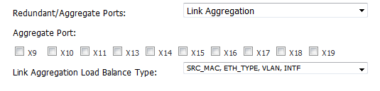
In the Redundant/Aggregate Ports drop-down menu, select Link Aggregation. The Aggregate Port option displays with a checkbox for each of the currently unassigned interfaces on the firewall.
|
|
NOTE: After an interface is assigned to a Link Aggregation Group, its configuration is governed by the Link Aggregation master interface, and it cannot be configured independently. In the Interface Settings table, the interface's zone is displayed as Aggregate Port and the Configuration icon is removed.
|
|
6
|
From the Link Aggregation Load Balance Type drop-down menu, select how link aggregation is to be load balanced:
|
|
•
|
SRC_MAC, ETH_TYPE, VLAN, INTF (default)
|
|
7
|
|
2
|
|
3
|
|
1
|
On the Network > Interfaces page, click the Configure icon for the interface that is to be designated the master of the Link Aggregation Group. The Edit Interface dialog displays.
|
|
2
|
Click on the Advanced tab.
|
|
3
|
|
4
|
In the Redundant/Aggregate Ports drop-down menu, select Port Redundancy. The Redundant Port drop-down menu displays with a checkbox for each of the currently unassigned interfaces on the firewall.
|
|
6
|
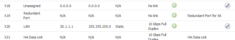
Click OK. In the Interface Settings table, the interface's zone is displayed as Redundant Port, and the Configuration icon is removed.
|
|
1
|
Navigate to the Network > Interfaces page.
|
|
2
|
At the bottom of the Interface Settings table, click Add Interface. The Add Interface dialog displays.
|
|
3
|
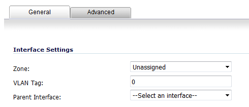
Select a zone to assign to the interface: LAN, WAN, DMZ, WLAN, or a custom zone. The zone assignment does not have to be the same as the parent (physical) interface. In fact, the parent interface can even remain Unassigned.
|
|
•
|
|
•
|
|
8
|
Click OK.
|