|
•
|
|
•
|
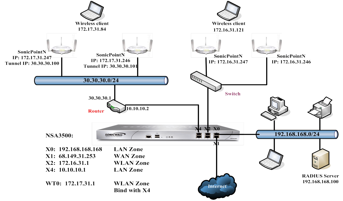
SonicWALL DHCP-based Discovery Protocol (SDDP) - SDDP enables the Dell SonicWALL security appliance and the SonicPoints to discover each other automatically across Layer 3 networks. The appliance acts as the DHCP server and the SonicPoint acts as the DHCP client, which allows the Dell sonicWALL . Any routers or other network devices between the appliance and the SonicPoint must be configured to allow DHCP relay.
|
|
•
|
SonicWALL Control and Provisioning Wireless Access Point (SCAPWAP) - SCAPWAP is a Dell SonicWALL extension of CAPWAP that is customized for Dell SonicWALL products. The Dell SonicWALL network security appliance gateway manages the SonicPoints using SCAPWAP, independent of Layer 2 and Layer 3 networks. The Dell SonicWALL security appliance and the SonicPoints must be configured to do mutual authentication using either a pre-shared key or a public key-based certificates.
|
|
•
|
SonicWALL SSLVPN-based Management Protocol (SSMP) - SSMP is based on the Dell SonicWALL SSL VPN infrastructure and enables the SonicPoints to be managed over the Internet by a Dell SonicWALL security appliance. In this case, a single NetExtender SSL VPN tunnel is established between the appliance and the SonicPoint. All of a user’s SonicPoint traffic to the appliance is tunneled over this single NetExtender session.
|
|
•
|
Local Layer 2 Management – When a Dell SonicWALL network security appliance and its SonicPoints are deployed in the same Layer 2 network, the existing Layer 2 discovery protocol, SDP, is used to manage the access points.
|
|
•
|
Local Layer 3 Management – When SonicPoints are deployed outside of the Layer 2 network, but within the same Intranet as the Dell SonicWALL security appliance (for example when there is a third-party router between the Dell SonicWALL security appliance and the SonicPoints), Layer 3 management protocols can be used to manage the access points.
|
|
•
|
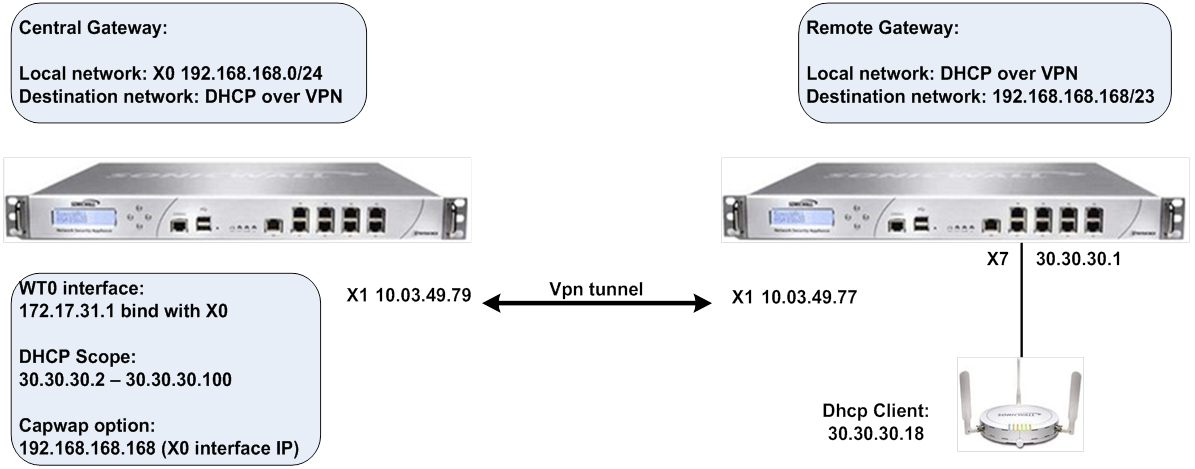
Remote Layer 3 Management– When SonicPoints are deployed in a remote site across the Internet cloud, Layer 3 management can be used to manage the remote network access points. A single SSL VPN NetExtender tunnel is established between the SonicPoint and the remote the Dell SonicWALL security appliance. Each wireless client does not need to install and launch NetExtender to establish an SSL VPN tunnel. All the wireless clients share the same VPN tunnel. This reduces the number of NetExtender licenses required on the Dell SonicWALL security appliance. It also eliminates the need to establish individual tunnels for each SonicPoint.
|
|
1
|
Navigate to the Network > Interfaces page.
|
|
2
|
Click the Configure icon for the X4 interface.
|
The Edit Interface window appears.
|
3
|
|
4
|
|
5
|
In the IP Address field, enter the IP address of the interface. For example, 10.10.10.1. A default value of 0.0.0.0 is displayed.
|
|
6
|
in the Subnet Mask field, enter the subnet mask for the interface. For example, 255.255.255.0 (this is the default value).
|
|
7
|
Optionally, enter a comment in the Comment field. This comment displays in the Comment column of the Interface Settings table of Network > Interfaces.
|
|
•
|
HTTPS – Enables remote management of the DELL SonicWALL through the HTTPS protocol.
|
|
TIP: If you select HTTPS, the Add rule to enable redirect from HTTP to HTTPS option is enabled automatically.
|
|
•
|
Ping – Enables remote management of the DELL SonicWALL through the Ping protocol.
|
|
•
|
SNMP – Enables remote management of the DELL SonicWALL through the SNMP protocol.
|
|
•
|
SSH – Enables remote management of the DELL SonicWALL through the SSH protocol.
|
|
9
|
Optionally, select HTTPS for User Login to enable users with management rights to log in to the DELL SonicWALL. The HTTP option is dimmed (unavailable).
|
|
10
|
If you did not select HTTPS for Management, but did select HTTPS for User Login, to enable users logging in from HTTP to be redirected to HTTPS, select Add rule to enable redirect from HTTP to HTTPS.
|
|
11
|
Click OK.
|
|
1
|
Navigate to the Network > DHCP Server page.
|
|
2
|
|
3
|
|
4
|
In the Option Name field, enter a descriptive name for the DHCP option object, such as cap.
|
|
5
|
From the Option Number drop-down menu, select 138 (CAPWAP AC IPv4 Address List). The Option Array option becomes active, and the Option Type is set to IP Address.
|
|
6
|
|
7
|
In the Option Value field, enter the IP address for the X0 interface you configured in Configuring the Access Controller Interface . For example, 10.10.10.1.
|
|
8
|
Click OK. The new Option Object is displayed in the Option Objects section of the DHCP Advanced Settings window.
|
|
9
|
Click OK.
|
|
1
|
Navigate to the Network > DHCP Server page.
|
|
2
|
Under the DHCPv4 Server Lease Scopes table, click Add Dynamic. The Dynamic Range Configuration window appears.
|
|
3
|
Select the Enable this DHCP Scope option. This is selected by default.
|
|
4
|
Enter the appropriate IP addresses or values in the Range Start, Range End, Lease Time (minutes) (default is 1440 minutes), Default Gateway, and Subnet Mask boxes.
|
|
5
|
Click the Advanced tab.
|
|
6
|
In the DHCP Generic Option Group menu, select the DHCP Option Object you created in Configuring the DHCP Server .
|
|
7
|
Select the Send Generic options always option.
|
|
8
|
|
1
|
Navigate to the Network > Interfaces page.
|
|
2
|
From the Add Interface drop-down menu, select Tunnel Interface. The Add Tunnel Interface window appears.
|
|
3
|
|
4
|
|
5
|
From the Tunnel Source Interface drop-down menu, select the interface, such as X4 in this scenario.
|
|
6
|
|
7
|
In the IP Address field, enter the IP address for the WLAN tunnel interface. For example, 172.17.31.1.
|
|
8
|
In the Subnet Mask box, enter the subnet mask. The default is 255.255.255.0.
|
|
9
|
From the SonicPoint Limit drop-down menu, select the maximum number of SonicPoints for this interface. The defaults are dependent upon the type of SonicPoints being used.
|
|
10
|
(Optional) In the Comment field, enter a descriptive comment. This comment is displayed in the Comment field.
|
|
11
|
If you did not specify a web management protocol in Configuring the Access Controller Interface , select one or more Management options: HTTPS, Ping, SNMP, SSH.
|
|
TIP: If you select HTTPS, the Add rule to enable redirect from HTTP to HTTPS option is enabled automatically.
|
|
12
|
If you did not specify a login protocol in Configuring the Access Controller Interface , optionally select HTTPS for User Login to enable users with management rights to log in to the DELL SonicWALL. The HTTP option is dimmed (unavailable).
|
|
13
|
If you did not select HTTPS for Management, but did select HTTPS for User Login, to enable users logging in from HTTP to be redirected to HTTPS, select Add rule to enable redirect from HTTP to HTTPS.
|
|
14
|
|
15
|
To verify, navigate to the Firewall > Access Rules page. You should see a Layer 3 Management option in the Access Rules table.
|
|
1
|
Navigate to the Network > Routing page.
|
|
2
|
|
3
|
|
4
|
From the Destination drop-down menu, select the address object of the default gateway. The default is Any.
|
|
5
|
|
6
|
|
7
|
From the Interface drop-down menu, select an interface. For this scenario, select X4.
|
|
8
|
|
9
|
This scenario extends the previous example, Configuring Basic SonicPoint Layer 3 Management , by adding Virtual Access Points (VAPs) for the SonicPoints.
|
1
|
Navigate to the Network > Interfaces page.
|
|
2
|
|
3
|
|
4
|
|
5
|
From the Parent Interface drop-down menu, select WT0.
|
|
6
|
|
7
|
In the IP Address field, enter the IP address for the WLAN. For example, 172.4.1.1. The default is 0.0.0.0.
|
|
8
|
In the Subnet Mask field, enter the subnet mask. For example, 255.255.255.0. The default is 255.255.255.0.
|
|
9
|
From the SonicPoint Limit drop-down menu, select the maximum number of SonicPoints for this interface. For this scenario, select 48 SonicPoints. The default is 64 SonicPoints.
|
|
10
|
(Optional) In the Comment field, enter a descriptive comment. This comment is displayed in the Comment field.
|
|
11
|
If you did not specify a web management protocol in Configuring the Access Controller Interface , select one or more Management options: HTTPS, Ping, SNMP, SSH.
|
|
TIP: If you select HTTPS, the Add rule to enable redirect from HTTP to HTTPS option is enabled automatically.
|
|
12
|
If you did not specify a login protocol in Configuring the Access Controller Interface , optionally select HTTPS for User Login to enable users with management rights to log in to the DELL SonicWALL. The HTTP option is dimmed (unavailable).
|
|
13
|
If you did not select HTTPS for Management, but did select HTTPS for User Login, to enable users logging in from HTTP to be redirected to HTTPS, select Add rule to enable redirect from HTTP to HTTPS.
|
|
14
|
|
1
|
Navigate to the SonicPoint > Virtual Access Point page.
|
|
2
|
|
3
|
In the Name field, enter a descriptive name for the VAP.
|
|
4
|
in the SSID field, enter a SSID that represents the Layer 3 management network. For example, wirelessDev_L3_vap.
|
|
5
|
From the VLAN ID drop-down menu, select the VLAN Tag ID that you configured in Configuring a WLAN Interface for VAPs . For example, 4.
|
|
6
|
Select the Enable Virtual Access Point option. By default, this option is selected
|
|
7
|
Click OK. The virtual access points table is updated.
|
|
8
|
|
1
|
Navigate to the SonicPoint > Virtual Access Point page.
|
|
2
|
In the Virtual Access Points Groups table, click Add Group. The Add Virtual Access Point Group window displays.
|
|
3
|
In the Virtual AP Group Name field, enter a name for the VAP group. For example, L3 VAP Group. The Available Virtual AP Objects box should be populated with the VAP objects you created in Configuring a VAP Object .
|
|
4
|
Move the VAP objects you want from the Available Virtual AP Objects box to the Member of Virtual AP Group box.
|
|
5
|
|
1
|
Navigate to the SonicPoint > SonicPoints page and scroll to the SonicPointN Provisioning Profiles section.
|
|
2
|
Click the Configure icon for the SonicPoint you want to configure. The Edit SonicPoint <type> Profile dialog appears.
|
|
3
|
Select the Enable SonicPoint option. This is selected by default.
|
|
4
|
From the <802.11n> Radio <0/1> Virtual AP Group drop-down menu in the Virtual Access Point Settings section, select the Virtual AP Group you created in Configuring a VAP Group . For example, L3 VAP Group.
|
|
5
|
Click OK.
|
|
1
|
On the Central Gateway management interface, navigate to the VPN > Settings page.
|
|
2
|
|
3
|
|
4
|
From the Authentication Method drop-down menu, select the method you want. For example, IKE using Preshared Secret. This is the default.
|
|
5
|
In the Name field, enter a descriptive name for the VPN tunnel. For example, VPN to Central Gateway.
|
|
6
|
In the IPSec Primary Gateway Name or Address field, enter the IP address of the remote gateway. For example, 10.03.49.77.
|
|
8
|
Click the Network tab.
|
|
9
|
|
10
|
From the Choose local network from list drop-down menu, select X0 Subnet.
|
|
11
|
Under Remote Networks, select the option you want and, if applicable, and the network you want from the associated drop-down menu.
|
|
12
|
Click the Advanced tab.
|
|
13
|
Select the Allow SonicPoint N Layer 3 Management option.
|
|
14
|
|
15
|
Navigate to the VPN > DHCP over VPN page.
|
|
16
|
|
17
|
|
19
|
Click OK.
|
|
1
|
On the Remote Gateway management interface, navigate to the VPN > Settings page.
|
|
2
|
|
3
|
|
4
|
From the Authentication Method drop-down menu, select the appropriate method for your network. For example, IKE using Preshared Secret. This is the default.
|
|
5
|
|
6
|
In the IPSec Primary Gateway Name or Address field, enter the IP address of the remote gateway. For example, 10.03.49.79.
|
|
7
|
Click the Network tab.
|
|
8
|
|
9
|
From the Choose local network from list drop-down menu, select X1 Subnet.
|
|
10
|
Under Remote Networks, select the option you want and, if appropriate, the network from the associated drop-down menu. This is the Choose destination network from list.
|
|
TIP: If you have not created an address object for your remote gateway, you can do so by selecting Create new address object from one of the menus.
|
|
11
|
Under Remote Networks, select Create new address object from the appropriate menu. The Add Address Object window appears.
|
|
12
|
In the Name field, enter Remote Gateway X0 Subnet.
|
|
13
|
|
14
|
|
15
|
In the Network field, enter the IP address of the remote gateway. For example, 192.168.168.0.
|
|
16
|
In the Netmask/Prefix Length field, enter the mask. For example, 255.255.255.0.
|
|
17
|
Click OK.
|
|
18
|
Click the Advanced tab.
|
|
19
|
Select the Allow SonicPoint N Layer 3 Management option.
|
|
20
|
|
21
|
Navigate to the VPN > DHCP over VPN page.
|
|
22
|
|
23
|
|
24
|
From the DHCP lease bound to drop-down menu, select the interface that is connected to the SonicPoint. For example, Interface X4.
|
|
25
|
(Optional) Select the Accept DHCP Request from bridged WLAN interface option if you want it.
|
|
26
|
In the Relay IP Address field, enter the IP address of the interface connected to the SonicPoint. For example 30.30.30.1.
|
|
27
|
In the Remote Management IP Address field, enter the IP address that is used to manage this Dell SonicWALL security appliance remotely from behind the Central Gateway.
|
|
NOTE: This IP address was configured in Configuring the Access Controller Interface , and must be reserved in the DHCP scope on the DHCP server. In the example it is 10.10.10.1.
|
|
28
|
Select the Block traffic through tunnel when IP spoof detected option.
|
|
29
|
Select the Obtain temporary lease from local DHCP server if tunnel is down option.
|
|
30
|
|
31
|
Click OK.
|
|
1
|
Navigate to the Network > Interfaces page.
|
|
2
|
From the Add Interface drop-down menu in the Interface Settings section, select Add WLAN Tunnel Interface. The Add WLAN Tunnel Interface window is displayed.
|
|
3
|
|
4
|
|
5
|
|
6
|
|
7
|
In the IP Address field, select 172.17.31.1.
|
|
8
|
In the Subnet Mask field, enter 255.255.255.0. This is the default.
|
|
9
|
From the SonicPoint Limit drop-down menu, select the maximum number of SonicPoints allowed on your network. For example, 48 SonicPoints. The default is 64 SonicPoints.
|
|
10
|
Optionally, enter a comment in the Comment field.
|
|
11
|
|
1
|
On the Central Gateway management interface, navigate to the Network > DHCP Server page.
|
|
2
|
|
3
|
|
4
|
In the Option Name field, enter a descriptive name, such as capwap or CAPWAP DHCP.
|
|
5
|
|
6
|
In the Option Value field, enter the IP address you want to use for the DHCP group. For example, 192.168.168.168.
|
|
7
|
Click OK to add the DHCP Option Object.
|
|
8
|
|
1
|
Navigate to the Network > DHCP Server page.
|
|
2
|
|
3
|
Select Enable this DHCP Scope.
|
|
4
|
In the Range Start field, enter the IP address at which to start the DHCP range; for example, 30.30.30.2. The range values must be within the same subnet as the Default Gateway; for example, 30.30.30.2 to 30.30.30.100.
|
|
5
|
In the Range End field, enter the IP address at which to end the DHCP range. For example, 30.30.30.100.
|
|
6
|
|
7
|
In the Default Gateway field, enter the IP address of the default gateway. This value is the IP address of the interface connected to the SonicPoint. For example, 30.30.30.1.
|
|
8
|
In the Subnet Mask field, enter the subnet mask of the default gateway. For example, 255.255.255.0.
|
|
9
|
Click the Advanced tab.
|
|
10
|
In the DHCP Generic Options section, from the DHCP Generic Option Group drop-down menu, select the CAPWAP DHCP option created in Configuring the CAPWAP DHCP Option Object on the Central Gateway .
|
|
11
|
Select the Send Generic options always option. This is the default.
|
|
12
|