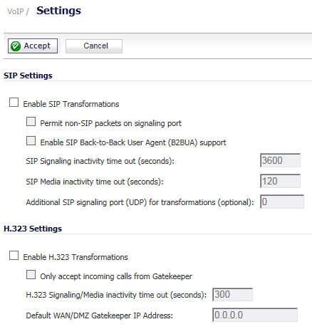
You configure VoIP through settings on the VoIP > Settings page. This page is divided into two sections: SIP Settings and H.323 Settings.
|
1
|
The Enable SIP Transformations is not selected by default. Select this option to:
|
|
•
|
NAT translates Layer 3 addresses, but not the Layer 7 SIP/SDP addresses, which is why you need to select Enable SIP Transformations to transform the SIP messages.
|
TIP: In general, you should select the Enable SIP Transformations checkbox unless there is another NAT traversal solution that requires this feature to be turned off. SIP Transformations works in bi-directional mode, meaning messages are transformed going from LAN to WAN and vice versa.
|
When Enable SIP Transformations is selected, the other options become available.
|
2
|
Selecting Permit non-SIP packets on signaling port enables applications such as Apple iChat and MSN Messenger, which use the SIP signaling port for additional proprietary messages. This checkbox is disabled by default.
|
|
3
|
If the SIP Proxy Server is being used as a B2BUA, enable the Enable SIP Back-to-Back User Agent (B2BUA) support setting. This option is disabled by default and should be enabled only when the firewall can see both legs of a voice call (for example, when a phone on the LAN calls another phone on the LAN).
|
|
TIP: If there is no possibility of the firewall seeing both legs of voice calls (for example, when calls will only be made to and received from phones on the WAN), the Enable SIP Back-to-Back User Agent (B2BUA) support setting should be disabled to avoid unnecessary CPU usage.
|
|
4
|
Use the SIP Signaling inactivity time out (seconds) and SIP Media inactivity time out (seconds) options to define the amount of time a call can be idle (no traffic exchanged) before the firewall blocks further traffic. A call goes idle when placed on hold. The default time value for:
|
|
•
|
SIP Signaling inactivity time out is 3600 seconds (60 minutes).
|
|
•
|
SIP Media inactivity time out is 120 seconds (2 minutes).
|
|
5
|
Use the Additional SIP signaling port (UDP) for transformations setting to specify a non-standard UDP port to carry SIP signaling traffic. Normally, SIP signaling traffic is carried on UDP port 5060. However, a number of commercial VOIP services use different ports, such as 1560. When this setting is non zero (0, the default), the security appliance performs SIP transformation on these non-standard ports.
|
|
6
|
Click Accept.
|
|
1
|
Select Enable H.323 Transformation to allow stateful H.323 protocol-aware packet content inspection and modification by the firewall. This option is disabled by default. When the option is selected, the other H.323 options become active.
|
Disable the Enable H.323 Transformation to bypass the H.323 specific processing performed by the firewall.
|
2
|
Select Only accept incoming calls from Gatekeeper to ensure all incoming calls go through the Gatekeeper for authentication. The Gatekeeper refuses calls that fail authentication.
|
|
3
|
In the H.323 Signaling/Media inactivity time out (seconds) field, specify the amount of time a call can be idle before the firewall blocks further traffic. A call goes idle when placed on hold. The default time is 300 seconds (5 minutes).
|
|
4
|
The Default WAN/DMZ Gatekeeper IP Address field has a default value of 0.0.0.0. Enter the default H.323 Gatekeeper IP address in this field to allow LAN-based H.323 devices to discover the Gatekeeper using the multicast address 225.0.1.41. If you do not enter an IP address, multicast discovery messages from LAN-based H.323 devices go through the configured multicast handling.
|
|
5
|
Click Accept.
|
|
NOTE: You must select Bandwidth Management on the Network > Interfaces page for the WAN interface before you can configure bandwidth management for network access rules.
|
|
1
|
Go to the Firewall > Access Rules page.
|
|
2
|
|
3
|
|
4
|
|
5
|
|
6
|
Select the service or group of services affected by the access rule from the Service drop-down menu.
|
|
•
|
For H.323, select one of the following or select Create New Group and add the following services to the group:
|
|
•
|
For SIP, select SIP.
|
|
7
|
Select the source of the traffic affected by the access rule from the Source drop-down menu. Selecting Create New Network displays the Add Address Object dialog.
|
|
8
|
|
a
|
Enter the lowest and highest IP addresses in the range in the Starting IP Address: and Ending IP Address fields.
|
|
9
|
Select the destination of the traffic affected by the access rule from the Destination drop-down menu. Selecting Create New Network displays the Add Address Object dialog.
|
|
10
|
From the Users Allowed drop-down menu, add the user or user group affected by the access rule.
|
|
11
|
Select a schedule from the Schedule drop-down menu if you want to allow VoIP access only during specified times. The default schedule is Always on. You can specify schedule objects on the System > Schedules page.
|
|
12
|
Enter any comments to help identify the access rule in the Comments field.
|
|
13
|
|
14
|
|
15
|
Enter the maximum amount of bandwidth available to the Rule at any time in the Maximum Bandwidth field.
|
|
16
|
Assign a priority from 0 (highest) to 7 (lowest) in the Bandwidth Priority drop-down menu. For higher VoIP call quality, ensure VoIP traffic receives HIGH priority.
|
|
17
|
Click Add.
|