SonicOS includes the VoIP configuration settings on the VoIP > Settings page. This page is divided into three configuration settings sections: General Settings, SIP Settings, and H.323 Settings.
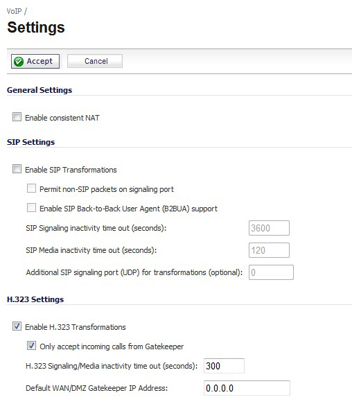
To enable Consistent NAT, select the Enable Consistent NAT option and click Accept. This option is disabled by default.
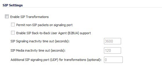
Selecting Enable SIP Transformations transforms SIP messages between LAN (trusted) and WAN/DMZ (untrusted). You need to check this setting when you want the firewall to do the SIP transformation. If your SIP proxy is located on the public (WAN) side of the firewall and SIP clients are on the LAN side, the SIP clients by default embed/use their private IP address in the SIP/Session Definition Protocol (SDP) messages that are sent to the SIP proxy, hence these messages are not changed and the SIP proxy does not know how to get back to the client behind the firewall. Selecting Enable SIP Transformations enables the firewall to go through each SIP message and change the private IP address and assigned port. Enable SIP Transformation also controls and opens up the RTP/RTCP ports that need to be opened for the SIP session calls to happen. NAT translates Layer 3 addresses but not the Layer 7 SIP/SDP addresses, which is why you need to select Enable SIP Transformations to transform the SIP messages.
|
TIP: In general, you should check the Enable SIP Transformations box unless there is another NAT traversal solution that requires this feature to be turned off. SIP Transformations works in bi-directional mode, meaning messages are transformed going from LAN to WAN and vice versa.
|
Selecting Permit non-SIP packets on signaling port enables applications such as Apple iChat and MSN Messenger, which use the SIP signaling port for additional proprietary messages. Enabling this checkbox may open your network to malicious attacks caused by malformed or invalid SIP traffic. This checkbox is disabled by default.
The Enable SIP Back-to-Back User Agent (B2BUA) support setting should be enabled when the firewall can see both legs of a voice call (for example, when a phone on the LAN calls another phone on the LAN). This setting should only be enabled when the SIP Proxy Server is being used as a B2BUA.
|
TIP: If there is no possibility of the firewall seeing both legs of voice calls (for example, when calls will only be made to and received from phones on the WAN), the Enable SIP Back-to-Back User Agent (B2BUA) support setting should be disabled to avoid unnecessary CPU usage.
|
SIP Signaling inactivity time out (seconds) and SIP Media inactivity time out (seconds) define the amount of time a call can be idle (no traffic exchanged) before the firewall blocks further traffic. A call goes idle when placed on hold. The default time value for SIP Signaling inactivity time out is 1800 seconds (30 minutes). The default time value for SIP Media inactivity time out is 120 seconds (2 minutes).
The Additional SIP signaling port (UDP) for transformations setting allows you to specify a non-standard UDP port used to carry SIP signaling traffic. Normally, SIP signaling traffic is carried on UDP port 5060. However, a number of commercial VOIP services use different ports, such as 1560. Using this setting, the security appliance performs SIP transformation on these non-standard ports.
Select Enable H.323 Transformation in the H.323 Settings section and click Accept to allow stateful H.323 protocol-aware packet content inspection and modification by the firewall. The firewall performs any dynamic IP address and transport port mapping within the H.323 packets, which is necessary for communication between H.323 parties in trusted and untrusted networks/zones. Disable the Enable H.323 Transformation to bypass the H.323 specific processing performed by the firewall.
Select Only accept incoming calls from Gatekeeper to ensure all incoming calls go through the Gatekeeper for authentication. The Gatekeeper will refuse calls that fail authentication.
The H.323 Signaling/Media inactivity time out (seconds) field specifies the amount of time a call can be idle before the firewall blocks further traffic. A call goes idle when placed on hold. The default time value for H.323 Signaling/Media inactivity time out is 300 seconds (5 minutes).
The Default WAN/DMZ Gatekeeper IP Address field has a default value of 0.0.0.0. Enter the default H.323 Gatekeeper IP address in this field to allow LAN-based H.323 devices to discover the Gatekeeper using the multicast address 225.0.1.41. If you do not enter an IP address, multicast discovery messages from LAN-based H.323 devices will go through the configured multicast handling.
BWM configurations begin by enabling BWM on the relevant WAN interface, and specifying the available bandwidth on the interface in Kbps. This is performed from the Network > Interfaces page by selecting the Configure icon for the WAN interface, and navigating to the Advanced tab:
Once one or both BWM settings are enabled on the WAN interface and the available bandwidth has been declared, a Bandwidth tab will appear on Access Rules. See Configuring VoIP Access Rules for more information.
|
1
|
Select Network > Interfaces.
|
|
2
|
Click the Edit icon in the Configure column in the WAN (X1) line of the Interfaces table. The Edit Interface window is displayed.
|
|
3
|
Click the Advanced tab.
|
|
4
|
Check Enable Egress (Outbound) Bandwidth Management and enter the available bandwidth in the Available Interface Egress Bandwidth Management field.
|
|
5
|
Check Enable Ingress (Inbound) Bandwidth Management and enter the available bandwidth in the Available Interface Ingress Bandwidth Management field.
|
|
6
|
Click OK.
|
|
NOTE: You must select Bandwidth Management on the Network > Interfaces page for the WAN interface before you can configure bandwidth management for network access rules.
|
|
1
|
Go to the Firewall > Access Rules page.
|
|
2
|
|
3
|
|
4
|
|
5
|
|
•
|
For H.323, select one of the following or select Create New Group and add the following services to the group:
|
|
•
|
For SIP, select SIP
|
|
7
|
Select the source of the traffic affected by the access rule from the Source list. Selecting Create New Network displays the Add Address Object window.
|
|
8
|
If you want to define the source IP addresses that are affected by the access rule, such as restricting certain users from accessing the Internet, select Range in the Type: drop-down menu. The enter the lowest and highest IP addresses in the range in the Starting IP Address: and Ending IP Address fields.
|
|
9
|
Select the destination of the traffic affected by the access rule from the Destination list. Selecting Create New Network displays the Add Address Object window.
|
|
10
|
From the Users Allowed menu, add the user or user group affected by the access rule.
|
|
11
|
Select a schedule from the Schedule menu if you want to allow VoIP access only during specified times. The default schedule is Always on. You can specify schedule objects on the system > Schedules page.
|
|
12
|
Enter any comments to help identify the access rule in the Comments field.
|
|
13
|
Click the Bandwidth tab.
|
|
14
|
|
15
|
Enter the maximum amount of bandwidth available to the Rule at any time in the Maximum Bandwidth field.
|
|
16
|
Assign a priority from 0 (highest) to 7 (lowest) in the Bandwidth Priority list. For higher VoIP call quality, ensure VoIP traffic receives HIGH priority.
|
You can enable the logging of VoIP events on the Log > Settings page. Log entries are displayed on the Log > Monitor page. To enable logging of VoIP, see Log > Settings .