802.1p and DSCP QoS

Topics:

Enabling 802.1p

SonicOS supports layer 2 and layer 3 CoS methods for broad interoperability with external systems participating in QoS enabled environments. The layer 2 method is the IEEE 802.1p standard wherein 3-bits of an additional 16-bits inserted into the header of the Ethernet frame can be used to designate the priority of the frame, as illustrated in the following figure:

Figure 41. Ethernet data frame

.

TPID: Tag Protocol Identifier begins at byte 12 (after the 6 byte destination and source fields), is 2 bytes long, and has an Ether type of 0x8100 for tagged traffic.
802.1p: The first three bits of the TCI (Tag Control Information – beginning at byte 14, and spanning 2 bytes) define user priority, giving eight (2^3) priority levels. IEEE 802.1p defines the operation for these 3 user priority bits.
CFI: Canonical Format Indicator is a single-bit flag, always set to zero for Ethernet switches. CFI is used for compatibility reasons between Ethernet networks and Token Ring networks. If a frame received at an Ethernet port has a CFI set to 1, then that frame should not be forwarded as it is to an untagged port.
VLAN ID: VLAN ID (starts at bit 5 of byte 14) is the identification of the VLAN. It has 12-bits and allows for the identification of 4,096 (2^12) unique VLAN ID’s. Of the 4,096 possible IDs, an ID of 0 is used to identify priority frames, and an ID of 4,095 (FFF) is reserved, so the maximum possible VLAN configurations are 4,094.

802.1p support begins by enabling 802.1p marking on the interfaces which you wish to have process 802.1p tags. 802.1p can be enabled on any Ethernet interface on any SonicWALL appliance.

The behavior of the 802.1p field within these tags can be controlled by Access Rules. The default 802.1p Access Rule action of None will reset existing 802.1p tags to 0, unless otherwise configured (see Managing QoS Marking for details).

Enabling 802.1p marking will allow the target interface to recognize incoming 802.1p tags generated by 802.1p capable network devices, and will also allow the target interface to generate 802.1p tags, as controlled by Access Rules. Frames that have 802.1p tags inserted by SonicOS will bear VLAN ID 0.

802.1p tags will only be inserted according to Access Rules, so enabling 802.1p marking on an interface will not, at its default setting, disrupt communications with 802.1p-incapable devices.

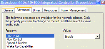
802.1p requires the specific support by the networking devices with which you wish to use this method of prioritization. Many voice and video over IP devices provide support for 802.1p, but the feature must be enabled. Check your equipment’s documentation for information on 802.1p support if you are unsure. Similarly, many server and host network cards (NICs) have the ability to support 802.1p, but the feature is usually disabled by default. On Win32 operating systems, you can check for and configure 802.1p settings on the Advanced tab of the Properties page of your network card. If your card supports 802.1p, it will list it as 802.1p QoS, 802.1p Support, QoS Packet Tagging or something similar:

To process 802.1p tags, the feature must be present and enabled on the network interface. The network interface will then be able to generate packets with 802.1p tags, as governed by QoS capable applications. By default, general network communications will not have tags inserted so as to maintain compatibility with 802.1p-incapable devices.

It should also be noted that when performing a packet capture (for example, with the diagnostic tool Ethereal) on 802.1p capable devices, some 802.1p capable devices will not show the 802.1q header in the packet capture. Conversely, a packet capture performed on an 802.1p-incapable device will almost invariably show the header, but the host will be unable to process the packet.

Before moving on to Managing QoS Marking , it is important to introduce ‘DSCP Marking’ because of the potential interdependency between the two marking methods, as well as to explain why the interdependency exists.

Figure 42. DSCP marking: Example scenario

In the scenario above, we have Remote Site 1 connected to ‘Main Site’ by an IPsec VPN. The company uses an internal 802.1p/DSCP capable VoIP phone system, with a private VoIP signaling server hosted at the Main Site. The Main Site has a mixed gigabit and Fast-Ethernet infrastructure, while Remote Site 1 is all Fast Ethernet. Both sites employ 802.1p capable switches for prioritization of internal traffic.

1
2
a
b

When the firewall sent the packet across the VPN/WAN link, it could include the DSCP tag in the packet, but it is not possible to include the 802.1p tag. This would have the effect of losing all prioritization information for the VoIP traffic, because when the packet arrived at the Remote Site, the switch would have no 802.1p MAC layer information with which to prioritize the traffic. The Remote Site switch would treat the VoIP traffic the same as the lower-priority file transfer because of the link saturation, introducing delay—maybe even dropped packets—to the VoIP flow, resulting in call quality degradation.

So how can critical 802.1p priority information from the Main Site LAN persist across the VPN/WAN link to Remote Site LAN? Through the use of QoS Mapping.

QoS Mapping is a feature which converts layer 2 802.1p tags to layer 3 DSCP tags so that they can safely traverse (in mapped form) 802.1p-incapable links; when the packet arrives for delivery to the next 802.1p-capable segment, QoS Mapping converts from DSCP back to 802.1p tags so that layer 2 QoS can be honored.

In our above scenario, the firewall at the Main Site assigns a DSCP tag (for example, value 48) to the VoIP packets, as well as to the encapsulating ESP packets, allowing layer 3 QoS to be applied across the WAN. This assignment can occur either by preserving the existing DSCP tag, or by mapping the value from an 802.1p tag, if present. When the VoIP packets arrive at the other side of the link, the mapping process is reversed by the receiving SonicWALL, mapping the DSCP tag back to an 802.1p tag.

3

DSCP Marking

DSCP (Differentiated Services Code Point) marking uses 6-bits of the 8-bit ToS field in the IP Header to provide up to 64 classes (or code points) for traffic. Since DSCP is a layer 3 marking method, there is no concern about compatibility as there is with 802.1p marking. Devices that do not support DSCP will simply ignore the tags, or at worst, they will reset the tag value to 0.

Figure 43. DSCP marking: IP packet

The above diagram depicts an IP packet, with a close-up on the ToS portion of the header. The ToS bits were originally used for Precedence and ToS (delay, throughput, reliability, and cost) settings, but were later repurposed by RFC2474 for the more versatile DSCP settings.

The following table shows the commonly used code points, as well as their mapping to the legacy Precedence and ToS settings.


Table 123. DSCP marking: Commonly used code points

DSCP

DSCP Description

Legacy IP Precedence

Legacy IP ToS (D, T, R)

0

Best effort

0 (Routine – 000)

-

8

Class 1

1 (Priority – 001)

-

10

Class 1, gold (AF11)

1 (Priority – 001)

T

12

Class 1, silver (AF12)

1 (Priority – 001)

D

14

Class 1, bronze (AF13)

1 (Priority – 001)

D, T

16

Class 2

2 (Immediate – 010)

-

18

Class 2, gold (AF21)

2 (Immediate – 010)

T

20

Class 2, silver (AF22)

2 (Immediate – 010)

D

22

Class 2, bronze (AF23)

2 (Immediate – 010)

D, T

24

Class 3

3 (Flash – 011)

-

26

Class 3, gold (AF31)

3 (Flash – 011)

T

27

Class 3, silver (AF32)

3 (Flash – 011)

D

30

Class 3, bronze (AF33)

3 (Flash – 011)

D, T

32

Class 4

4 (Flash Override – 100)

-

34

Class 4, gold (AF41)

4 (Flash Override – 100)

T

36

Class 4, silver (AF42)

4 (Flash Override – 100)

D

38

Class 4, bronze (AF43)

4 (Flash Override – 100)

D, T

40

Express forwarding

5 (CRITIC/ECP1 – 101)

-

46

Expedited forwarding (EF)

5 (CRITIC/ECP – 101)

D, T

48

Control

6 (Internet Control – 110)

-

56

Control

7 (Network Control – 111)

-


1
ECP: Elliptic Curve Group

DSCP marking can be performed on traffic to/from any interface and to/from any zone type, without exception. DSCP marking is controlled by Access Rules, from the QoS tab, and can be used in conjunction with 802.1p marking, as well as with SonicOS’ internal bandwidth management.

Topics:
DSCP Marking and Mixed VPN Traffic

Among their many security measures and characteristics, IPsec VPNs employ anti-replay mechanisms based upon monotonically incrementing sequence numbers added to the ESP header. Packets with duplicate sequence numbers are dropped, as are packets that do not adhere to sequence criteria. One such criterion governs the handling of out-of-order packets. SonicOS provides a replay window of 64 packets, i.e. if an ESP packet for a Security Association (SA) is delayed by more than 64 packets, the packet will be dropped.

This should be considered when using DSCP marking to provide layer 3 QoS to traffic traversing a VPN. If you have a VPN tunnel that is transporting a diversity of traffic, some that is being DSCP tagged high priority (e.g. VoIP), and some that is DSCP tagged low-priority, or untagged/best-effort (e.g. FTP), your service provider will prioritize the handling and delivery of the high-priority ESP packets over the best-effort ESP packets. Under certain traffic conditions, this can result in the best-effort packets being delayed for more than 64 packets, causing them to be dropped by the receiving SonicWALL’s anti-replay defenses.

If symptoms of such a scenario emerge (e.g. excessive retransmissions of low-priority traffic), it is recommended that you create a separate VPN policy for the high-priority and low-priority classes of traffic. This is most easily accomplished by placing the high-priority hosts (e.g. the VoIP network) on their own subnet.

Configure for 802.1p CoS 4 – Controlled load

If you want to change the inbound mapping of DSCP tag 15 from its default 802.1p mapping of 1 to an 802.1p mapping of 2, it would have to be done in two steps because mapping ranges cannot overlap. Attempting to assign an overlapping mapping will give the error DSCP range already exists or overlaps with another range. First, you will have to remove 15 from its current end-range mapping to 802.1p CoS 1 (changing the end-range mapping of 802.1p CoS 1 to DSCP 14), then you can assign DSCP 15 to the start-range mapping on 802.1p CoS 2.

QoS Mapping

The primary objective of QoS Mapping is to allow 802.1p tags to persist across non-802.1p compliant links (e.g. WAN links) by mapping them to corresponding DSCP tags before sending across the WAN link, and then mapping from DSCP back to 802.1p upon arriving at the other side:

Figure 44. QoS mapping

NOTE: Mapping will not occur until you assign Map as an action of the QoS tab of an Access Rule. The mapping table only defines the correspondence that will be employed by an Access Rule’s Map action.

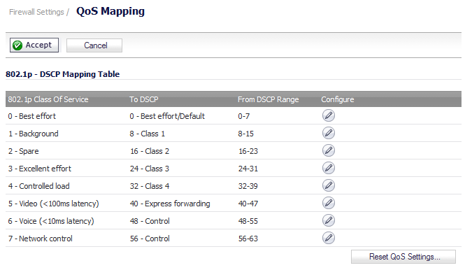
For example, according to the default table, an 802.1p tag with a value of 2 will be outbound mapped to a DSCP value of 16, while a DSCP tag of 43 will be inbound mapped to an 802.1 value of 5.

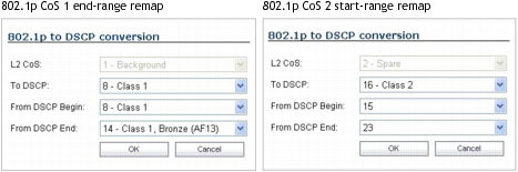
Each of these mappings can be reconfigured. If you wanted to change the outbound mapping of 802.1p tag 4 from its default DSCP value of 32 to a DSCP value of 43, you can click the Configure icon for 4 – Controlled load and select the new To DSCP value from the drop-down box:

You can restore the default mappings by clicking the Reset QoS Settings button.

Managing QoS Marking

QoS marking is configured from the QoS tab of Access Rules under the Firewall > Access Rules page of the management interface. Both 802.1p and DSCP marking as managed by SonicOS Access Rules provide 4 actions: None, Preserve, Explicit, and Map. The default action for DSCP is Preserve and the default action for 802.1p is None.

The following table describes the behavior of each action on both methods of marking:


Table 124. QoS marking: Behavior

Action

802.1p (layer 2 CoS)

DSCP (layer 3)

Notes

None

When packets matching this class of traffic (as defined by the Access Rule) are sent out the egress interface, no 802.1p tag will be added.

The DSCP tag is explicitly set (or reset) to 0.

If the target interface for this class of traffic is a VLAN subinterface, the 802.1p portion of the 802.1q tag will be explicitly set to 0. If this class of traffic is destined for a VLAN and is using 802.1p for prioritization, a specific Access Rule using the Preserve, Explicit, or Map action should be defined for this class of traffic.

Preserve

Existing 802.1p tag will be preserved.

Existing DSCP tag value will be preserved.


Explicit

An explicit 802.1p tag value can be assigned (0-7) from a drop-down menu that will be presented.

An explicit DSCP tag value can be assigned (0-63) from a drop-down menu that will be presented.

If either the 802.1p or the DSCP action is set to Explicit while the other is set to Map, the explicit assignment occurs first, and then the other is mapped according to that assignment.

Map

The mapping setting defined in the Firewall Settings > QoS Mapping page will be used to map from a DSCP tag to an 802.1p tag

The mapping setting defined in the Firewall Settings > QoS Mapping page will be used to map from an 802.1 tag to a DSCP tag. An additional checkbox will be presented to Allow 802.1p Marking to override DSCP values. Selecting this checkbox will assert the mapped 802.1p value over any DSCP value that might have been set by the client. This is useful to override clients setting their own DSCP CoS values.

If Map is set as the action on both DSCP and 802.1p, mapping will only occur in one direction: if the packet is from a VLAN and arrives with an 802.1p tag, then DSCP will be mapped from the 802.1p tag; if the packet is destined to a VLAN, then 802.1p will be mapped from the DSCP tag.

For example, refer to the following figure which provides a bi-directional DSCP tag action.

HTTP access from a Web-browser on 192.168.168.100 to the Web server on 10.50.165.2 will result in the tagging of the inner (payload) packet and the outer (encapsulating ESP) packets with a DSCP value of 8. When the packets emerge from the other end of the tunnel, and are delivered to 10.50.165.2, they will bear a DSCP tag of 8. When 10.50.165.2 sends response packets back across the tunnel to 192.168.168.100 (beginning with the very first SYN/ACK packet) the Access Rule will tag the response packets delivered to 192.168.168.100 with a DSCP value of 8.

This behavior applies to all four QoS action settings for both DSCP and 802.1p marking.

One practical application for this behavior would be configuring an 802.1p marking rule for traffic destined for the VPN zone. Although 802.1p tags cannot be sent across the VPN, reply packets coming back across the VPN can be 802.1p tagged on egress from the tunnel. This requires that 802.1p tagging is active of the physical egress interface, and that the [Zone] > VPN Access Rule has an 802.1p marking action other than None.

After ensuring 802.1p compatibility with your relevant network devices, and enabling 802.1p marking on applicable SonicWALL interfaces, you can begin configuring Access Rules to manage 802.1p tags.

Referring to the following figure, the Remote Site 1 network could have two Access Rules configured as follows:


Table 125. Remote site 1: Sample access rule configuration

Setting

Access Rule 1

Access Rule 2

General Tab

Action

Allow

Allow

From Zone

LAN

VPN

To Zone

VPN

LAN

Service

VOIP

VOIP

Source

Lan Primary Subnet

Main Site Subnets

Destination

Main Site Subnets

Lan Primary Subnet

Users Allowed

All

All

Schedule

Always on

Always on

Enable Logging

Enabled

Enabled

Allow Fragmented Packets

Enabled

Enabled

Qos Tab

DSCP Marking Action

Map

Map

Allow 802.1p Marking to override DSCP values

Enabled

Enabled

802.1p Marking Action

Map

Map

The first Access Rule (governing LAN>VPN) would have the following effects:

VoIP traffic (as defined by the Service Group) from LAN Primary Subnet destined to be sent across the VPN to Main Site Subnets would be evaluated for both DSCP and 802.1p tags.

Assuming returned traffic has been DSCP tagged (CoS = 48) by the firewall at the Main Site, the return traffic will be 802.1p tagged with CoS = 6 on egress.

To examine the effects of the second Access Rule (VPN>LAN), we’ll look at the Access Rules configured at the Main Site.


Table 126. Main site: Sample access rule configurations

Setting

Access Rule 1

Access Rule 2

General Tab

Action

Allow

Allow

From Zone

LAN

VPN

To Zone

VPN

LAN

Service

VOIP

VOIP

Source

Lan Subnets

Remote Site 1 Subnets

Destination

Remote Site 1 Subnets

Lan Subnets

Users Allowed

All

All

Schedule

Always on

Always on

Enable Logging

Enabled

Enabled

Allow Fragmented Packets

Enabled

Enabled

Qos Tab

DSCP Marking Action

Map

Map

Allow 802.1p Marking to override DSCP values

Enabled

Enabled

802.1p Marking Action

Map

Map

VoIP traffic (as defined by the Service Group) arriving from Remote Site 1 Subnets across the VPN destined to LAN Subnets on the LAN zone at the Main Site would hit the Access Rule for inbound VoIP calls. Traffic arriving at the VPN zone will not have any 802.1p tags, only DSCP tags.