All filters set on this page are applied to both packet capture and packet mirroring.
|
1
|
Navigate to the Dashboard > Packet Monitor page.
|
|
2
|
|
3
|
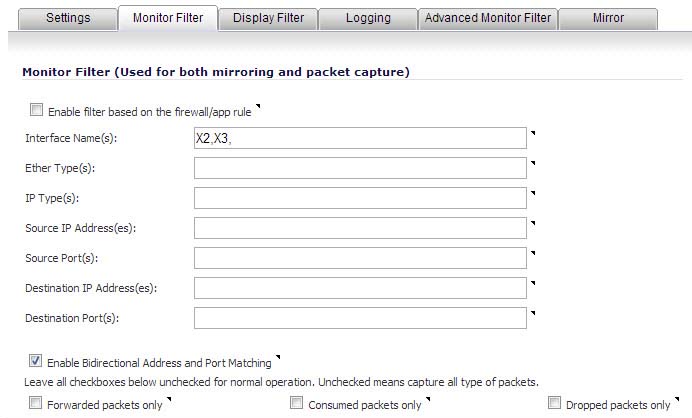
Click the Monitor Filter tab.
|
|
4
|
Choose to Enable filter based on the firewall rule if you are using firewall rules to capture specific traffic. When this option is selected, only packets that match the firewall rule will be monitored.
|
|
NOTE: Before the Enable filter based on the firewall rule option is selected, be certain you have selected one or more access rules on which to monitor packet traffic. This configuration is done from the Firewall > Access Rules page of the SonicOS management interface.
|
|
•
|
Interface Name(s) - Specify the name of the interface on which packet capture will be performed. You can specify up to ten interfaces separated by commas. Interface names should be the same as those displayed on the Network > Interfaces page; for example:
|
|
•
|
|
•
|
You can use a negative value to configure all interfaces except the one(s) specified; for example: !X0, or !LAN.
|
•
|
Ether Type(s) - Specify the name of the Ethernet type on which filtering of the captured packets will be performed. You can specify up to ten Ethernet types separated by commas. Currently, the following Ethernet types are supported:
|
|
•
|
|
•
|
The latter two can be specified as just PPPoE.
This option is not case-sensitive. For example, to capture all supported types, you could enter: ARP, IP, IPv6, PPPOE.
You can use one or more negative values to capture all Ethernet types except those specified; for example: !ARP, !PPPoE.
You can also use hexadecimal values to represent the Ethernet types, or mix hex values with the standard representations; for example: ARP, 0x800, IP. Normally, you would only use hex values for Ethernet types that are not supported by acronym in SonicOS. See Supported Packet Types.
|
•
|
IP Type(s) - Specify the name of the IP packet type on which packet capture will be performed. You can specify up to ten IP types separated by commas. The following IP types are supported:
|
|
•
|
|
•
|
|
•
|
|
•
|
|
•
|
|
•
|
|
•
|
|
•
|
This option is not case-sensitive.
You can use one or more negative values to capture all IP types except those specified; for example: !TCP, !UDP.
You can also use hexadecimal values to represent the IP types, or mix hex values with the standard representations; for example: TCP, 0x1, 0x6. See Supported Packet Types.
|
•
|
Source IP Address(es) - Specify the source IP address on which packet capture will be performed. You can specify up to ten IP addresses separated by commas; for example: 10.1.1.1, 192.2.2.2, 2001::1, 2002::1. You can use one or more negative values to capture packets from all but the specified addresses; for example: !10.3.3.3, !10.4.4.4, !2001::1.
|
|
•
|
Source Port(s) - Specify the source Port Address on which packet capture will be performed. You can specify up to ten TCP and/or UDP port numbers separated by commas; for example: 20,21,22,25. You can use one or more negative values to capture packets from all but the specified ports; for example: !80,!8080.
|
|
•
|
Destination IP Address(es) - Specify the destination IP address on which packet capture will be performed. You can specify up to ten IP addresses separated by commas; for example: 10.1.1.1, 192.2.2.2, 2001::1, 2002::1. You can use one or more negative values to capture packets destined for all but the specified addresses; for example: !10.3.3.3, !10.4.4.4, !2001::1.
|
|
•
|
Destination Port(s) - Specify the destination Port Address on which packet capture will be performed. You can specify up to ten TCP and/or UDP port numbers separated by commas; for example: 20, 21, 22, 25. You can use one or more negative values to capture packets destined for all but the specified ports; for example: !80, !8080. Default ports are 25,10025.
|
|
•
|
Enable Bidirectional Address and Port Matching - Select this option to have IP addresses and ports specified in the Source or Destination fields on this page matched against both the source and destination address and port fields in each packet. This option is enabled by default.
|
|
•
|
Forwarded packets only - Select this option to monitor only packets that are forwarded by the firewall.
|
|
•
|
Consumed packets only - Select this option to monitor only packets that are consumed by internal sources within the firewall.
|
|
•
|
Dropped packets only - Select this option to monitor only packets that are dropped at the perimeter.
|