IPv4 and IPv6 IP addresses are accepted/displayed in the Network > Interfaces screens.
|
1
|
Click on the Configure icon
|
|
•
|
If you want to create a new zone, select Create new zone. The Add Zone window is displayed. See the Network > Zones page for instructions on adding a zone.
|
|
3
|
|
4
|
Enter the IP Address (Primary), and the IP Address (Secondary) if high availability is enabled, and the Subnet Mask of the zone in the IP Address (Primary), IP Address (Secondary), and Subnet Mask fields.
|
|
6
|
Enter any optional comment text in the Comment field. This text is displayed in the Comment column of the Interface table.
|
|
7
|
If you want to enable remote management of the SonicWALL appliance from this interface, select the supported management protocol(s): HTTP, HTTPS, SSH, Ping, SNMP, and/or SSH.
|
|
8
|
If you want to allow selected users with limited management rights to log in to the security appliance, select HTTP and/or HTTPS in User Login.
|
|
9
|
Click OK.
|
|
•
|
Static—For static IP addresses, enter the IP Address for the interface and Subnet Mask for the network.
|
|
•
|
Transparent Mode—For transparent mode, select an address object that contains the range of IP addresses you want to have access through this interface in the Transparent Range menu.
|
|
•
|
PortShield Switch Mode—For SonicWALL TZ 210, TZ 210W and NSA 240 appliances, you can configure interfaces for PortShield switch mode that manually groups ports together to share a common network subnet as well as common zone settings. For more information, refer to Configuring PortShield Groups .
|
|
•
|
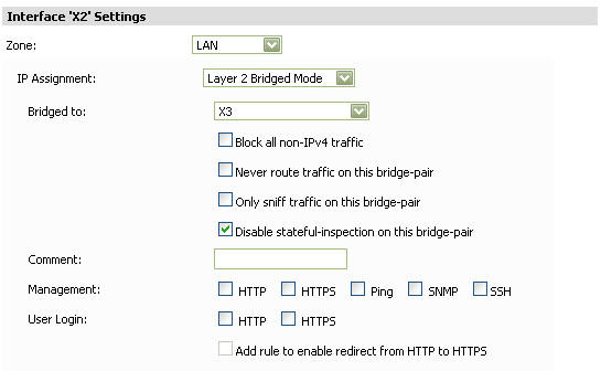
Layer 2 Bridged Mode—On appliances running SonicOS Enhanced 3.5 and 4.0 or higher, you can select Layer 2 Bridged Mode for physical interfaces in either the LAN or the DMZ zone. On appliances running SonicOS Enhanced 5.5 or higher, you can select Layer 2 Bridge Mode for the WLAN zone.
|
|
•
|
In the Bridged-to field, select a WAN, LAN, or DMZ interface with a static IP address.
|
|
•
|
Select Block all non-IPv4 traffic to allow only IPv4 traffic on this bridge-pair.
|
|
•
|
Select Never route traffic on this bridge-pair to prevent traffic from being routed to another interface.
|
|
•
|
Select Only sniff traffic on this bridge-pair to allow the bridged interface to be connected to a mirrored port on a switch in a one-arm mode to do intrusion detection by examining traffic going through the switch.
|
|
•
|
Select Disable stateful-inspection on this bridge-pair to enable asymmetric routing on this interface.
|
The Engage physical bypass on malfunction option enables Layer 2 Bridge Bypass Relay Control, also known as “Fail to Wire.” The bypass relay option provides the user the choice of avoiding disruption of network traffic by bypassing the firewall in the event of a malfunction. The bypass relay is closed for any unexpected anomaly (power failure, watchdog exception, fallback to safe-mode).
Selecting the Engage physical bypass on malfunction option automatically configures the other Layer 2 Bridge mode options as follows:
|
•
|
Block all non-IPv4 traffic - Disabled
|
|
•
|
Never route traffic - Enabled
|
|
•
|
Only sniff traffic - Disabled
|
|
•
|
Disable stateful-inspection - Not modified
|
|
•
|
Comment—Enter any comments regarding the interface.
|
|
•
|
Management—Select one or more of the following management options:
|
|
•
|
HTTP—Allows HTTP management over the interface.
|
|
•
|
HTTPS—Allows HTTPS management over the interface.
|
|
•
|
Ping—The interface responds to ping requests.
|
|
•
|
SNMP—The interface supports Simple Network Management Protocol (SNMP).
|
|
•
|
SSH—The interface supports Secure Shell (SSH) for CLI-based administration.
|
|
•
|
User Login—Select from the following user login options:
|
|
•
|
HTTP—When selected, you are able to login using HTTP.
|
|
•
|
HTTPS—When selected, you are able to login using HTTPS.
|
|
•
|
Add rule to enable redirect from HTTP to HTTPS—Redirects you to HTTPS when they attempt to access the device using HTTP. This option is only applicable when HTTPS access is enabled and HTTP access is not.
|
Wire Mode 2.0 can be configured on any zone (except wireless zones). Wire Mode is a simplified form of Layer 2 Bridge Mode, and is configured as a pair of interfaces. In Wire Mode, the destination zone is the Paired Interface Zone. Access rules are applied to the Wire Mode pair based on the direction of traffic between the source Zone and its Paired Interface Zone. For example, if the source Zone is WAN and the Paired Interface Zone is LAN, then WAN to LAN and LAN to WAN rules are applied, depending on the direction of the traffic.
In Wire Mode, administrators can enable Link State Propagation, which propagates the link status of an interface to its paired interface. If an interface goes down, its paired interface is forced down to mirror the link status of the first interface. Both interfaces in a Wired Mode pair always have the same link status.
In Wire Mode, administrators can Disable Stateful Inspection. When Disable Stateful Inspection is selected, Stateful Packet Inspection (SPI) is turned off. When Disable Stateful Inspection is not selected, new connections can be established without enforcing a 3-way TCP handshake. Disable Stateful Inspection must be selected if asymmetrical routes are deployed.
When the Bypass when SonicOS is restarting or down option is selected, and the Wire Mode Type is set to Secure, traffic continues to flow even when the SonicWALL Security Appliance is rebooting or is down. The Bypass when SonicOS is restarting or down option is always enabled and is not editable when Disable Stateful Inspection is selected.
|
1
|
|
2
|
|
3
|
|
4
|
|
5
|
|
6
|
Select Enable Link State Propagation.
|
|
7
|
Select Disable Stateful Inspection.
|
|
8
|
Select Bypass when SonicOS is restarting or down.
|
|
9
|
Click OK.
|
|
1
|
On the Network > Interfaces page, click Configure for the interface you want to configure for Wire Mode.
|
|
2
|
|
3
|
To configure the Interface for Tap Mode, in the Mode / IP Assignment pull-down menu, select Tap Mode (1-Port Tap) and click OK.
|
|
4
|
To configure the Interface for Wire Mode, in the Mode / IP Assignment pull-down menu, select Wire Mode (2-Port Wire).Click OK.
|
|
1
|
Select how the WAN connects to the Internet from the IP Assignment list box:
|
|
•
|
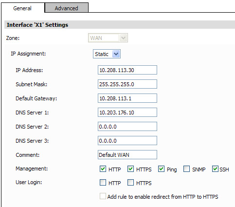
Static—Configure the following settings for static IP address interfaces:
|
|
•
|
IP Address—Enter the IP address of the interface.
|
|
•
|
Subnet Mask—Enter the subnet mask for the network.
|
|
•
|
Default Gateway—IP address of the WAN gateway.
|
|
•
|
DNS Server 1-3—IP addresses of the DNS Servers.
|
|
•
|
Comment—Enter any comments regarding the interface.
|
|
•
|
DHCP—Configure the following settings if the WAN IP address will use DHCP:
|
|
•
|
Host Name—Specifies the host name of the SonicWALL device on the WAN interface.
|
|
•
|
Comment—Enter any comments regarding the interface.
|
|
•
|
IP Address, Subnet Mask, Gateway (Router) Address, and DNS Server 1-3—These settings are automatically filled in by DHCP.
|
|
•
|
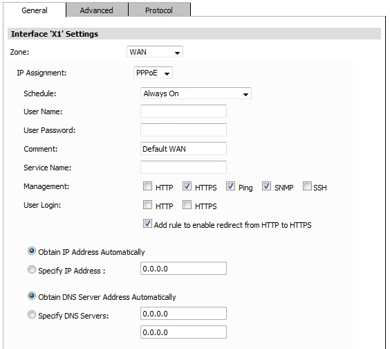
PPPoE—Configure the following settings if the WAN IP address uses PPPoE:
|
|
•
|
User Name—Enter username provided by the ISP.
|
|
•
|
Password—Enter the password used to authenticate the username with the ISP. This field is case-sensitive.
|
|
•
|
Comment—Enter any comments regarding the interface.
|
|
•
|
Service Name—Enter the name of a service that must be supported by PPPoE servers that respond to a client connection request. The service name can be up to 50 characters. Many installations use the system name as a service name, for example “sonicwall-server” or “redback-server.” If the service name is left blank the client connects to any service.
|
To configure the SonicWALL appliance(s) to dynamically obtain an IP address, select Obtain an IP Address automatically.
To configure the SonicWALL appliance(s) to use a fixed IP address, select Use the following IP Address and enter the IP address.
To configure the SonicWALL appliance(s) to obtain the DNS server information automatically, select Obtain DNS Server Address Automatically.
To specify DNS servers, select Specify DNS Servers and enter the DNS Server IP addresses.
|
•
|
Click the Protocol tab.
|
|
•
|
Inactivity Disconnect—Specify how long (in minutes) the SonicWALL appliance waits before disconnecting from the Internet, and select the check box.
|
|
•
|
Strictly use LCP echo packets for server keep-alive—This check box is enabled when the client recognizes that the server relies on Link Control Protocol (LCP) echo requests for keeping the PPPoE connection alive.
|
|
•
|
Disconnect the PPPoE client if the server does not send traffic for __ minutes—Select this check box and enter the number of minutes to wait without traffic before the connection is ended. When enabled, the PPPoE client monitors traffic from the server on the tunnel and disconnects when no traffic is seen for the specified time period.
|
|
•
|
PPTP—Configure the following settings if the WAN IP address will use PPTP:
|
|
•
|
User Name—Enter username provided by the ISP.
|
|
•
|
User Password—Enter the password used to authenticate the username with the ISP. This field is case-sensitive.
|
|
•
|
PPTP Server IP Address—this information is provided by your ISP.
|
|
•
|
PPTP (Client) Host Name—this information is provided by your ISP.
|
|
•
|
Comment—Enter any comments regarding the interface.
|
|
•
|
Inactivity Disconnect—Specify how long (in minutes) the SonicWALL appliance waits before disconnecting from the Internet.
|
|
•
|
Select from the following from the PPTP IP Assignment list box:
|
|
•
|
To configure the SonicWALL appliance(s) to use a fixed IP address, select Static and enter the IP address, subnet mask, and gateway IP address.
|
|
•
|
L2TP—Configure the following settings if the WAN IP address uses L2TP:
|
|
•
|
User Name—Enter username provided by the ISP.
|
|
•
|
User Password—Enter the password used to authenticate the username with the ISP. This field is case-sensitive.
|
|
•
|
L2TP Server IP Address—this information is provided by your ISP.
|
|
•
|
L2TP (Client) Host Name—this information is provided by your ISP.
|
|
•
|
Comment—Enter any comments regarding the interface.
|
|
•
|
Inactivity Disconnect—Specify how long (in minutes) the SonicWALL appliance waits before disconnecting from the Internet.
|
|
•
|
Select from the following from the L2TP IP Assignment list box:
|
To configure the SonicWALL appliance(s) to use a fixed IP address, select Static and enter the IP address, subnet mask, and gateway IP address.
|
2
|
Select one or more of the following management options:
|
|
•
|
HTTP—When selected, allows HTTP management from the interface.
|
|
•
|
HTTPS—When selected, allows HTTPS management from the interface.
|
|
•
|
Ping—When selected, the interface responds to ping requests.
|
|
•
|
SNMP—When selected, the interface supports Simple Network Management Protocol (SNMP).
|
|
3
|
User Login—Select from the following user login options:
|
|
•
|
HTTP—When selected, you are able to login using HTTP.
|
|
•
|
HTTPS—When selected, you are able to login using HTTPS.
|
|
•
|
Add rule to enable redirect from HTTP to HTTPS—Redirects you to HTTPS when they attempt to access the device using HTTP. This option is only applicable when HTTPS access is enabled and HTTP access is not.
|
|
4
|
|
1
|
Click the Advanced tab and configure the following Ethernet settings:
|
|
•
|
Link Speed—To configure the interface to automatically negotiate Ethernet settings, select Auto Negotiate. If you want to specify the forced Ethernet speed and duplex, select the appropriate setting.
|
|
•
|
Use Default MAC Address—Select to use the default MAC address.
|
|
•
|
Override Default MAC Address—Select to manually enter the MAC address.
|
|
•
|
Enable flow reporting—Select to enable flow reporting on flows created for this interface. This check box is available on SonicWALL appliances running 5.9 and higher firmware.
|
|
•
|
Enable Multicast Support—Select to enable multicast on the interface.
|
|
•
|
Interface MTU—Specify the size of the Maximum Transmission Unit (MTU) in octets (default: 1500).
|
|
•
|
Enable 802.1p tagging—QoS Marking is controlled per Access Rule from the Firewall > Access Rules page. Packets sent out this interface are tagged with VLAN id=0 and carry 802.1p priority information. Devices connected to this interface should support priority frames. This check box is available on SonicWALL appliances running 5.9 and higher firmware.
|
|
•
|
To shutdown the port, click Shutdown Port. A warning pop-up window displays, asking if you wish to administratively want to shut down the port. This check box is only available for SuperMassive series appliances running SonicOS 6.1 and higher firmware images.
|
|
•
|
To fragment packets that are larger than this MTU, select Fragment non-VPN outbound packets larger than this Interface's MTU.
|
|
•
|
To block notifications that this interface can receive fragmented packets, select Do not send ICMP Fragmentation Needed for outbound packets over the Interface MTU.
|
|
•
|
To ignore Don’t Fragment (DF) bits from routers connected to the SonicWALL appliance, select Ignore Don't Fragment (DF) Bit.
|
|
2
|
Under the Expert Mode Settings heading, select Use Routed Mode - Add NAT Policy to prevent outbound\inbound translation to enable Routed Mode for the interface. Routed Mode provides an alternative for NAT for routing traffic between separate public IP address ranges. NAT translations are automatically disabled for the interface, and all inbound and outbound traffic is routed to the WAN interface
|
|
•
|
In the Set NAT Policy's outbound\inbound interface to pull-down menu, select the WAN interface that is to be used to route traffic for the interface. The firewall then creates “no-NAT” policies for both the configured interface and the selected WAN interface. These policies override any more general M21 NAT policies that might be configured for the interfaces.
|
|
3
|
Click OK.
|
Use the Bandwidth Management section of the Edit Interface screen to enable or disable the ingress and egress bandwidth management. Egress and Ingress available link bandwidth can be used to configure the upstream and downstream connection speeds in kilobits per second.
|
•
|
Enable Egress Bandwidth Management - Enables outbound bandwidth management.
|
|
•
|
Available Interface Egress Bandwidth (Kbps) - Specifies the available bandwidth for WAN interfaces in Kbps.
|
|
•
|
Enable Ingress Bandwidth Management - Enables inbound bandwidth management.
|
|
5
|
Available Interface Ingress Bandwidth (Kbps) - Specifies the available bandwidth for WAN interfaces in Kbps
|
|
6
|
|
•
|
To enable egress bandwidth management on this interface, select the check box and enter the bandwidth of the connection in the Available Interface Bandwidth field in kilobytes per second (Kbps).
|
|
•
|
To enable ingress bandwidth management on this interface, select the check box and enter the bandwidth of the connection in the Available Interface Bandwidth field in kilobytes per second (Kbps).
|
|
7
|
|
1
|
On the Network > Interfaces page, click the configure icon for the interface that is to be designated the master of the Link Aggregation Group. The Edit Interface window displays.
|
|
2
|
|
3
|
Click on the Advanced tab.
|
|
4
|
|
5
|
The Aggregate Port option is displayed with a check box for each of the currently unassigned interfaces on the firewall. Select up to three other interfaces to assign to the LAG.
|
|
6
|
(Wire Mode only) The Paired Interface Aggregate Port option is displayed, select up to three paired interfaces.
|
|
7
|
|
8
|
Click OK.
|
|
2
|
|
3
|
|
1
|
On the Network > Interfaces page, click the configure icon for the interface that is to be designated the master of the Link Aggregation Group. The Edit Interface window displays.
|
|
2
|
|
3
|
Click on the Advanced tab.
|
|
4
|
|
5
|
The Redundant Port pull-down menu is displayed, with all of the currently unassigned interfaces available. Select one of the interfaces.
|
|
6
|
|
7
|
Click OK.
|
|
1
|
At the bottom of the Network > Interfaces page, click Add VLAN Interface. The Add Interface window displays.
|
|
2
|
Select a Zone to assign to the interface. You can select LAN, DMZ, WLAN, or unassigned. The zone assignment does not have to be the same as the parent (physical) interface.
|
|
3
|
Enter a Portshield Interface Name for the sub-interface.
|
|
5
|
For LAN and DMZ, select Static or Transparent for the IP Assignment. WLAN interfaces use static IP addresses:
|
|
•
|
|
•
|
|
6
|
Management—Select from the following management options:
|
|
•
|
HTTP—When selected, allows HTTP management from the interface.
|
|
•
|
HTTPS—When selected, allows HTTPS management from the interface.
|
|
•
|
Ping—When selected, the interface responds to ping requests.
|
|
•
|
SNMP—When selected, the interface supports Simple Network Management Protocol (SNMP).
|
|
7
|
User Login—Select from the following user login options:
|
|
•
|
HTTP—When selected, you are able to login using HTTP.
|
|
•
|
HTTPS—When selected, you are able to login using HTTPS.
|
|
•
|
Add rule to enable redirect from HTTP to HTTPS—Redirects you to HTTPS when they attempt to access the device using HTTP. This option is only applicable when HTTPS access is enabled and HTTP access is not.
|
|
8
|
Check Create Default DHCP Lease Scope to indicate that the amount of time allowed for an IP address issued by DHCP will be the default.
|
|
9
|
Click OK.
|
To configure the WAN connection model for a SonicWALL appliance with WWAN capability running SonicOS Enhanced 3.6 or higher, navigate to the Network > Interfaces page and select one of the following options in the WAN Connection Model pull-down menu:
|
•
|
WWAN only—The WAN interface is disabled and the WWAN interface is used exclusively.
|
|
•
|
Ethernet only—The WWAN interface is disabled and the WAN interface is used exclusively.
|
|
•
|
Ethernet with WWAN Failover—The WAN interface is used as the primary interface and the WWAN interface is disabled. If the WAN connection fails, the WWAN interface is enabled and a WWAN connection is automatically initiated.
|
|
1
|
In the Interface Settings table, in the WWAN row, click Connect. The SonicWALL appliance attempts to connect to the WWAN service provider.
|
|
2
|
To disconnect a WWAN connection, click Disconnect.
|
|
1
|
Click on the Configure icon in the Configure column for the Interface you want to configure. The Edit Interface window is displayed.
|
|
2
|
Enter the IP Address (Primary), and the IP Address (Secondary) if high availability is enabled, and the Subnet Mask of the zone in the IP Address (Primary), IP Address (Secondary), and Subnet Mask fields.
|
|
3
|
Enter an IP address for a Default Gateway (optional).
|
|
4
|
Enter any optional comment text in the Comment field. This text is displayed in the Comment column of the Interface table.
|
|
5
|
If you want to enable remote management of the SonicWALL appliance from this interface, select the supported management protocol(s): HTTP, HTTPS, SSH, Ping, SNMP, and/or SSH.
|
|
6
|
If you want to allow selected users with limited management rights to log in to the security appliance, select HTTP and/or HTTPS in User Login.
|
|
7
|
To add a rule to redirect from HTTP to HTTPS, click Add rule to enable redirect from HTTP to HTTPS. This option is only visible if Allow management via HTTP is enabled on the System > Administration page.
|
|
8
|
Click OK.
|