|
1
|
Click the Configure icon of the Group you wish to configure on the Network > Failover & LB page. The Edit LB Group dialog displays.
|
|
2
|
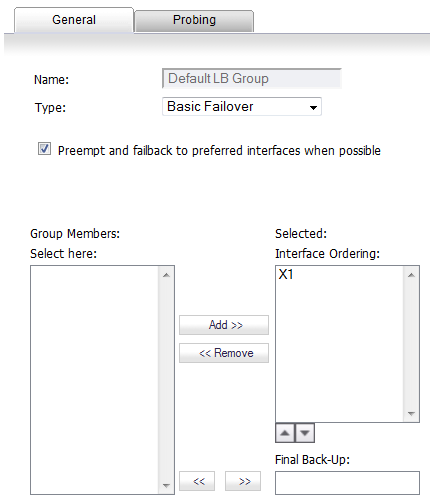
On the General tab, edit the display name of the Group in the Name field. The name of the default group cannot be changed.
|
|
3
|
From the Type drop-down menu, choose the type (or method) of LB; options change depending on the type selected:
|
|
•
|
Basic Failover—The four WAN interfaces use rank to determine the order of preemption when the Preempt checkbox has been enabled. Only a higher-ranked interface can preempt an Active WAN interface. This is selected by default.
|
|
•
|
Round Robin—This option now allows you to re-order the WAN interfaces for Round Robin selection. The default order is:
|
The Round Robin then returns to the Primary WAN to continue the order.
|
•
|
Spill-over—The bandwidth threshold applies to the Primary WAN. When the threshold is exceeded, new traffic flows are allocated to the Alternates in a Round Robin manner. If the Primary WAN bandwidth goes below the configured threshold, Round Robin stops, and outbound new flows will again be sent out only through the Primary WAN.
|
|
•
|
Ratio—A percentages can be set for each WAN in the LB group. To avoid problems associated with configuration errors, ensure that the percentage corresponds correctly to the WAN interface it indicates.
|
|
4
|
Depending on what you selected from the Type drop-down menu, one of these options display:
|
|
Preempt and failback to preferred interfaces when possible Select to enable rank to determine the order of preemption. Selected by default. |
|
|
When bandwidth exceeds BandwidthLimit Kbit/s on PrimaryInterface, new flows will go to the alternate group members in Round Robin manner |
|
|
Round Robin, Spill-over, and Ratio |
|
5
|
Add, delete, and order member interfaces in the Group Members: Select here:/Selected lists. The use of the selected members in the Selected list depends on the Type selected:
|
|
6
|
Add members by selecting a displayed interface from the Group Members: column, and then clicking the Add>> button.
|
|
7
|
You can order the entries in the Selected column by:
|
|
b
|
If you selected Ratio, instead of ordering the entries, you can specify the ratio of bandwidth for each interface. See Configuring Bandwidth as a Ratio .
|
a
|
Enter a percentage of bandwidth to be assigned to an interface in the percent (%) field. The total bandwidth for all interfaces should add up to 100%. The total percentage of bandwidth allocated is displayed.
|
You can modify the ratio by clicking the Modify Ratio button or have the ratios adjusted automatically by clicking the Auto Adjust button.
Delete members from the Selected: column by:
|
b
|
Clicking the <<Remove button.
|
|
•
|
Final Back-Up—An entry in this setting is an interface of “last resort,” that is, an interface that is used only when all other interfaces in the Selected: group are either unavailable or unusable. To specify a Final Back-Up interface, select an entry in the Group Members list, and then click the double right arrow
|
|
9
|
Click OK.
|
If Ratio is selected, the Add >> button is replaced by a percent (%) field and a Double Right Arrow button, and the Up/Down Arrow buttons are replaced with the Auto Adjust button.
If multiple interfaces are selected, you can either:
|
•
|
Click the Auto Adjust button to distribute the bandwidth equally among the interfaces.
|
|
1
|
Select the interface in the Selected column.
|
|
2
|
Click the Modify Ratio button.
|
|
3
|
|
4
|
Click the Modify Ratio button again. The percentage for the bandwidth and the total bandwidth allocated are updated.
|
|
1
|
Click the Configure icon of the Group you wish to configure on the Network > Failover & LB page. the Edit LB Group dialog displays.
|
|
2
|
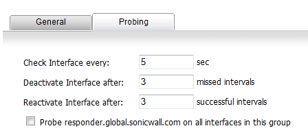
Click the Probing tab.
|
|
•
|
Check Interface every: n sec —The interval of health checks in units of seconds. The default value is 5 seconds.
|
|
•
|
Deactivate Interface after: n missed intervals—The number of failed health checks after which the interface sets to Failover. The default value is 6 seconds.
|
|
•
|
Reactivate Interface after: n successful intervals—The number of successful health checks after which the interface sets to Available. The default value is 3 seconds.
|
|
•
|
Probe responder.global.sonicwall.com on all interfaces in this group—Enable this checkbox to automatically set Logical/Probe Monitoring on all interfaces in the Group. When enabled, TCP probe packets are sent to the global SNWL host that responds to SNWL TCP packets, responder.global.sonicwall.com, using a target probe destination address of 204.212.170.23:50000. When this checkbox is selected, the rest of the probe configuration enables built-in settings automatically. The same probe will be applied to all four WAN Ethernet interfaces.
|
|
4
|
Click OK.
|