Using Ethernet Data Frame to Designate Priority
|
•
|
TPID: Tag Protocol Identifier begins at byte 12 (after the 6 byte destination and source fields), is 2 bytes long, and has an Ethertype of 0x8100 for tagged traffic.
|
|
•
|
802.1p: The first three bits of the TCI (Tag Control Information – beginning at byte 14, and spanning 2 bytes) define user priority, giving eight (2^3) priority levels. IEEE 802.1p defines the operation for these 3 user priority bits.
|
|
•
|
CFI: Canonical Format Indicator is a single-bit flag, always set to zero for Ethernet switches. CFI is used for compatibility reasons between Ethernet networks and Token Ring networks. If a frame received at an Ethernet port has a CFI set to 1, then that frame should not be forwarded as it is to an untagged port.
|
|
•
|
VLAN ID: VLAN ID (starts at bit 5 of byte 14) is the identification of the VLAN. It has 12-bits and allows for the identification of 4,096 (2^12) unique VLAN ID’s. Of the 4,096 possible IDs, an ID of 0 is used to identify priority frames, and an ID of 4,095 (FFF) is reserved, so the maximum possible VLAN configurations are 4,094.
|
The behavior of the 802.1p field within these tags can be controlled by Access Rules. The default 802.1p Access Rule action of None will reset existing 802.1p tags to 0, unless otherwise configured (see Managing QoS Marking for details).
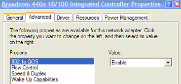
802.1p requires the specific support by the networking devices with which you wish to use this method of prioritization. Many voice and video over IP devices provide support for 802.1p, but the feature must be enabled. Check your equipment’s documentation for information on 802.1p support if you are unsure. Similarly, many server and host network cards (NICs) have the ability to support 802.1p, but the feature is usually disabled by default. On Win32 operating systems, you can check for and configure 802.1p settings on the Advanced tab of the Properties page of your network card. If your card supports 802.1p, it will list it as 802.1p QoS, 802.1p Support, QoS Packet Tagging or something similar:
Before moving on to Managing QoS Marking, it is important to introduce ‘DSCP Marking’ because of the potential interdependency between the two marking methods, as well as to explain why the interdependency exists.
802.1p and DSCP Qos: Sample configuration
In the scenario above, we have Remote Site 1 connected to ‘Main Site’ by an IPsec VPN. The company uses an internal 802.1p/DSCP capable VoIP phone system, with a private VoIP signaling server hosted at the Main Site. The Main Site has a mixed gigabit and Fast-Ethernet infrastructure, while Remote Site 1 is all Fast Ethernet. Both sites employ 802.1p capable switches for prioritization of internal traffic.
In our above scenario, the firewall at the Main Site assigns a DSCP tag (e.g. value 48) to the VoIP packets, as well as to the encapsulating ESP packets, allowing layer 3 QoS to be applied across the WAN. This assignment can occur either by preserving the existing DSCP tag, or by mapping the value from an 802.1p tag, if present. When the VoIP packets arrive at the other side of the link, the mapping process is reversed by the receiving SonicWall, mapping the DSCP tag back to an 802.1p tag.