Configuring Wire and Tap Mode

SonicOS supports Wire Mode and Tap Mode, which provide new methods non‑disruptive, incremental insertion into networks. Table 23 describes the wire and tap modes.


Table 23. Wire and Tap mode settings

Wire mode setting

Description

Bypass Mode

Bypass Mode allows for the quick and relatively non-interruptive introduction of firewall hardware into a network. Upon selecting a point of insertion into a network (for example, between a core switch and a perimeter firewall, in front of a VM server farm, at a transition point between data classification domains), the firewall is inserted into the physical data path, requiring a very short maintenance window. One or more pairs of switch ports on the firewall are used to forward all packets across segments at full line rates, with all the packets remaining on the firewall’s 240Gbps switch fabric rather than getting passed up to the multi-core inspection and enforcement path. While Bypass Mode does not offer any inspection or firewalling, this mode allows you to physically introduce the firewall into the network with a minimum of downtime and risk, and to obtain a level of comfort with the newly inserted component of the networking and security infrastructure. You can then transition from Bypass Mode to Inspect or Secure Mode instantaneously through a simple user-interface driven reconfiguration.

Inspect Mode

Inspect Mode extends Bypass Mode without functionally altering the low-risk, zero-latency packet path. Packets continue to pass through the firewall’s switch fabric, but they are also mirrored to the multi-core RF-DPI engine for the purposes of passive inspection, classification, and flow reporting. This reveals the firewall’s Application Intelligence and threat detection capabilities without any actual intermediate processing.

Secure Mode

Secure Mode is the progression of Inspect Mode, actively interposing the firewall’s multi-core processors into the packet processing path. This unleashes the inspection and policy engines’ full-set of capabilities, including Application Intelligence and Control, Intrusion Prevention Services, Gateway and Cloud-based Anti-Virus, Anti-Spyware, and Content Filtering. Secure Mode affords the same level of visibility and enforcement as conventional NAT or L2 Bridged Mode deployments, but without any L3/L4 transformations, and with no alterations of ARP or routing behavior. Secure Mode thus provides an incrementally attainable NGFW deployment requiring no logical and only minimal physical changes to existing network designs.

Secure mode should be used when creating wire-mode pairs for VLAN translation.

Tap Mode

Tap Mode provides the same visibility as Inspect Mode, but differs from the latter in that it ingests a mirrored packet stream via a single switch port on the firewall, eliminating the need for physically intermediated insertion. Tap Mode is designed for use in environments employing network taps, smart taps, port mirrors, or SPAN ports to deliver packets to external devices for inspection or collection. Like all other forms of Wire Mode, Tap Mode can operate on multiple concurrent port instances, supporting discrete streams from multiple taps.

Table 24 summarizes the key functional differences between modes of interface configuration:


Table 24. Wire modes: Functional differences

Interface configuration

Bypass mode

Inspect mode

Secure mode

Tap mode

L2 Bridge, Transparent, NAT, Route modes

Active/Active Clustering 1

No

No

No

No

Yes

Application Control

No

No

Yes

No

Yes

Application Visibility

No

Yes

Yes

Yes

Yes

ARP/Routing/NAT 1

No

No

No

No

Yes

Content Filtering

No

No

Yes

No

Yes

DHCP Server 1

No

No

No

No

Yes 2

DPI Detection

No

Yes

Yes

Yes

Yes

DPI Prevention

No

No

Yes

No

Yes

DPI-SSL1

No

No

Yes

No

Yes

High-Availability

Yes

Yes

Yes

Yes

Yes

Link-State Propagation 3

Yes

Yes

Yes

No

No

Stateful Packet Inspection

No

Yes

Yes

Yes

Yes

TCP Handshake Enforcement 4

No

No

No

No

Yes

Virtual Groups 1

No

No

No

No

Yes

VLAN Translation

No

No

Yes

No

No


1
These functions or services are unavailable on interfaces configured in Wire Mode, but remain available on a system-wide level for any interfaces configured in other compatible modes of operation.

2
Not available in L2 Bridged Mode.

3
Link State Propagation is a feature whereby interfaces in a Wire Mode pair will mirror the link-state triggered by transitions of their partners. This is essential to proper operations in redundant path networks.

4
Disabled by design in Wire Mode to allow for failover events occurring elsewhere on the network to be supported when multiple Wire Mode paths, or when multiple firewall units are in use along redundant or asymmetric paths.

Configuring an Interface for Wire Mode

Wire Mode can be configured on WAN, LAN, DMZ, and custom zones. Wire Mode is a simplified form of Layer 2 Bridged Mode, and is configured as a pair of interfaces. In Wire Mode, the destination zone is the Paired Interface Zone. Access rules are applied to the Wire Mode pair based on the direction of traffic between the source Zone and its Paired Interface Zone. For example, if the source Zone is WAN and the Paired Interface Zone is LAN, then WAN to LAN and LAN to WAN rules are applied, depending on the direction of the traffic.

In Wire Mode, you can enable Link State Propagation, which propagates the link status of an interface to its paired interface. If an interface goes down, its paired interface is forced down to mirror the link status of the first interface. Both interfaces in a Wire Mode pair always have the same link status.

In Wire Mode, you can Disable Stateful Inspection. When Disable Stateful Inspection is selected, Stateful Packet Inspection is turned off. When Disable Stateful Inspection is not selected, new connections can be established without enforcing a 3-way TCP handshake. Disable Stateful Inspection must be selected if asymmetrical routes are deployed.

To configure an interface for Wire Mode:
1
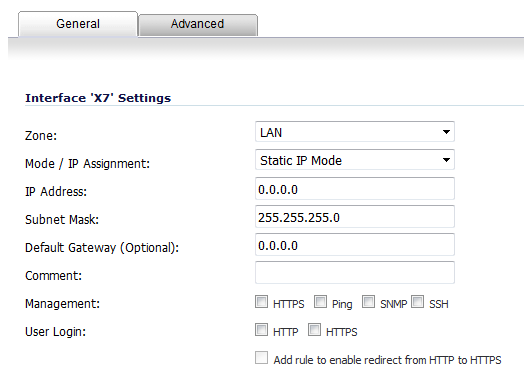
On the Network > Interfaces page, click the Configure icon for the interface you want to configure for Wire Mode. The Edit Interface dialog displays.

2
In the Zone drop-down menu, select any zone type except WLAN.
3
From in the Mode / IP Assignment drop-down menu, To configure the Interface for
Tap Mode, select Tap Mode (1-Port Tap).
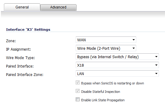
Wire Mode, select Wire Mode (2-Port Wire).
4
In the Wire Mode Type drop-down menu, select the appropriate mode:
5
In the Paired Interface drop-down menu, select the interface that will connect to the upstream firewall. The paired interfaces must be of the same type (two 1 GB interfaces or two 10 GB interfaces).
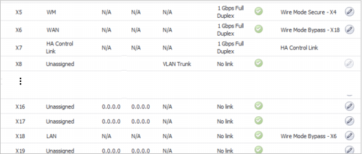
NOTE: Only unassigned interfaces are available in the Paired Interface drop-down menu. To make an interface unassigned, click on the Configure button for it, and in the Zone drop-down menu, select Unassigned.
6

Configuring Wire Mode for a WAN/LAN Zone Pair

The following configuration is an example of how Wire Mode can be configured. This example is for a WAN zone paired with a LAN zone. Wire Mode can also be configured for DMZ and custom zones.

To configure Wire Mode for a WAN/LAN Zone Pair:
1
Go to Network > Interfaces.
2
Configure icon for the interface you want to configure.

The Add/Edit Interface dialog displays.

3
Under the General tab, in the Mode/IP Assignment drop-down menu, select Wire Mode (2-Port Wire).

4
In the Zone drop-down menu, select WAN.
5
In the Paired Interface Zone drop-down menu, select LAN.
6
Click the OK button. The Interface Settings table is updated.