When the appliance is successfully registered, go to the System > Licenses page and click Synchronize under Manage Security Services Online. This will contact the firewall licensing server and ensure that the appliance is properly licensed.
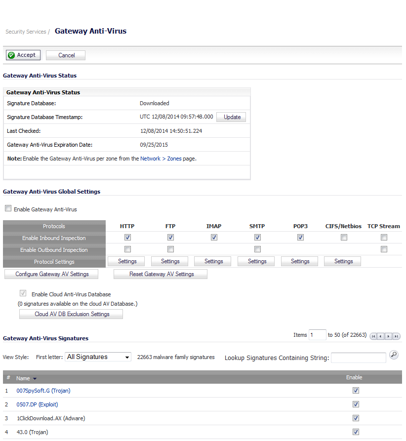
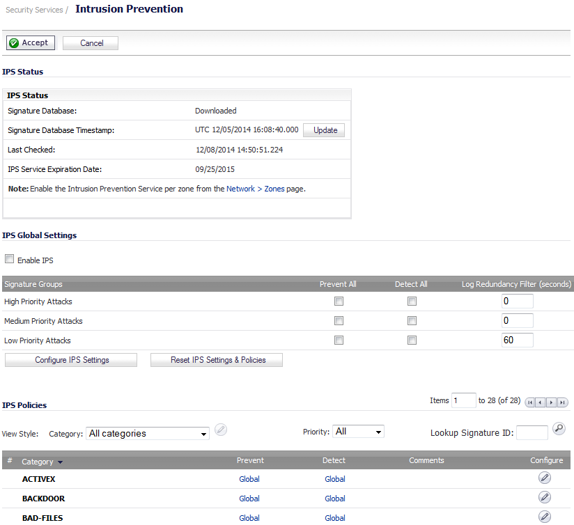
To check licensing status, go to the System > Status page and view the license status of all the UTM services (Gateway Anti-Virus, Anti-Spyware, and Intrusion Prevention).
On the Network > Zones page, for each zone you will be using, make sure that the security services are activated.
Then, on the Security Services page for each service, activate and configure the settings that are most appropriate for your environment.

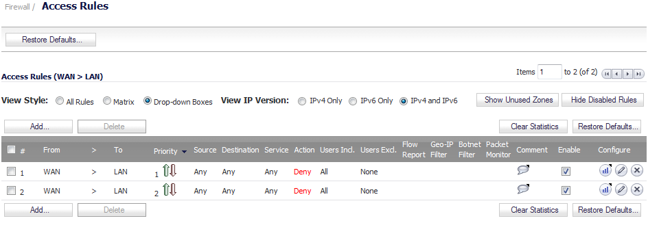
If you plan to manage the appliance from a different zone, or if you will be using a server such as the HP PCM+/NIM server for management, SNMP, or syslog services, create access rules for traffic between the zones. On the Firewall > Access Rules page, click on the icon for the intersection of the zone of the server and the zone that has users and servers (your environment may have more than one of these intersections). Create a new rule to allow the server to communicate with all devices in that zone.
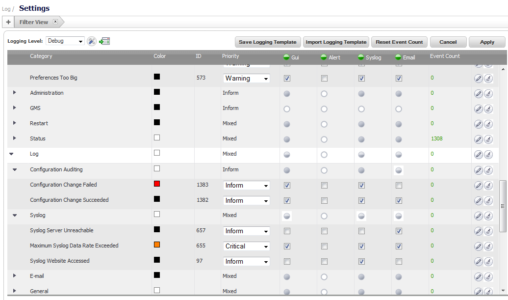
On the Log > Settings page, set the priority and other log settings.
Then, go to the Log > Name Resolution page and set the Name Resolution Method to DNS then NetBios. Click Accept to save and activate the change.

Refer to the L2 Bridge Interface Zone Selection for choosing a topology that best suits your network. In this example, we will be using a topology that most closely resembles the Simple L2 Bridge Topology.
Choose an interface to act as the Primary Bridge Interface. Refer to the L2 Bridge Interface Zone Selection for information in making this selection. In this example, we will use X1 (automatically assigned to the Primary WAN):
|
1
|
|
2
|
Click the Configure icon in the right column of the X1 (WAN) interface.
|
|
7
|
Click OK.
|
Choose an interface to act as the Secondary Bridge Interface. Refer to the L2 Bridge Interface Zone Selection for information in making this selection. In this example, we use X0 (automatically assigned to the LAN):
|
1
|
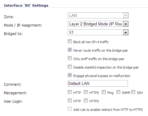
On the Network > Interfaces page, click the Configure icon in the right column of the X0 (LAN) interface.
|
|
2
|
|
3
|
|
4
|
|
5
|
You may optionally enable the Block all non-IPv4 traffic setting to prevent the L2 bridge from passing non-IPv4 traffic.
|
|
6
|
You may also optionally navigate to the VLAN Filtering tab to control VLAN traffic through the L2 bridge. By default, all VLANs are allowed:
|
|
•
|
Select Block listed VLANs (blacklist) from the drop-down list and add the VLANs you wish to block from the left pane to the right pane. All VLANs added to the right pane will be blocked, and all VLANs remaining in the left pane will be allowed.
|
|
•
|
Select Allow listed VLANs (whitelist) from the drop-down list and add the VLANs you wish to explicitly allow from the left pane to the right pane. All VLANs added to the right pane will be allowed, and all VLANs remaining in the left pane will be blocked.
|
|
7
|
Click OK.
|
The Network > Interfaces page displays the updated configuration:
When the L2 bypass relay is closed, the network cables attached to the bypassed interfaces (X0 and X1) are physically connected as if they were a single continuous network cable. The Engage physical bypass on malfunction option provides the user the choice of avoiding disruption of network traffic by bypassing the firewall in the event of a malfunction.
L2 bypass is only applicable to interfaces in Layer 2 Bridged Mode. The Engage physical bypass on malfunction option only appears when the Layer 2 Bridged Mode option is selected from the Mode / IP Assignment menu. This option does not appear unless a physical bypass relay exists between the two interfaces of the bridge-pair.
When the Engage physical bypass on malfunction option is enabled, the other Layer 2 Bridged Mode options are automatically set as follows:
|
•
|
Block all non-IPv4 traffic – disabled. When enabled, this option blocks all non-IPv4 Ethernet frames. So, this option is disabled.
|
|
•
|
Never route traffic on this bridge-pair – enabled. When enabled, this option prevents packets from being routed to a network other than the peer network of the bridged pair. So, this option is enabled.
|
|
•
|
Only sniff traffic on this bridge-pair – disabled. When enabled, traffic received on the bridge-pair interface is never forwarded. So, this option is disabled.
|
|
•
|
Disable stateful-inspection on this bridge-pair – unchanged. This option is not affected.
|
|
1
|
Go to the Network > Interfaces page.
|
|
2
|
Click on the Edit icon in the Configure column for the interface you want to configure. The Edit Interface window is displayed.
|
|
3
|
Select the Engage physical bypass on malfunction checkbox
|
|
4
|
Click OK to configure the interface.
|
When creating a zone (either as part of general administration, or as a step in creating a subinterface), a checkbox will be presented on the zone creation page to control the auto-creation of a GroupVPN for that zone. By default, only newly created Wireless type zones have Create GroupVPN for this zone enabled, although the option can be enabled for other zone types by selecting the checkbox during creation.
When configuring a VPN on an interface that is also configured for Layer 2 Bridged Mode, you must configure an additional route to ensure that incoming VPN traffic properly traverses the firewall. Navigate to the Network > Routing page, scroll to the bottom of the page, and click on the Add button. In the Add Route Policy window, configure the route as follows:
|
•
|
Source: ANY
|
|
•
|
Destination: custom-VPN-address-object (This is the address object for the local VPN tunnel IP address range.)
|
|
•
|
Service: ANY
|
|
•
|
Gateway: 0.0.0.0
|
|
•
|
Interface: X0
|