|
|
NOTE: This Initial Startup Guide (wizard) appears only when you first activate your TZ series appliance. After you have initially set up your appliance through the Startup Guide, the regular Setup Wizard (Guide) appears when you click Wizards in the upper right corner of the SonicOS management interface.
|
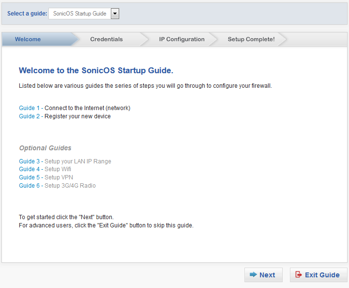
You can move backwards and forwards through the dialogs by clicking the Back  and Next
  keys respectively. As you complete steps and progress through the Setup Guide, the color of the completed dialog title changes color and a checkmark appears.
You can exit the guide at any time by clicking the Exit Guide  button. If you exit before completing the configuration, a dialog displays requesting confirmation of exiting without saving any settings:
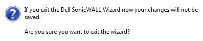
Click OK to exit the wizard, No to continue the configuration.
|
2
|
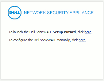
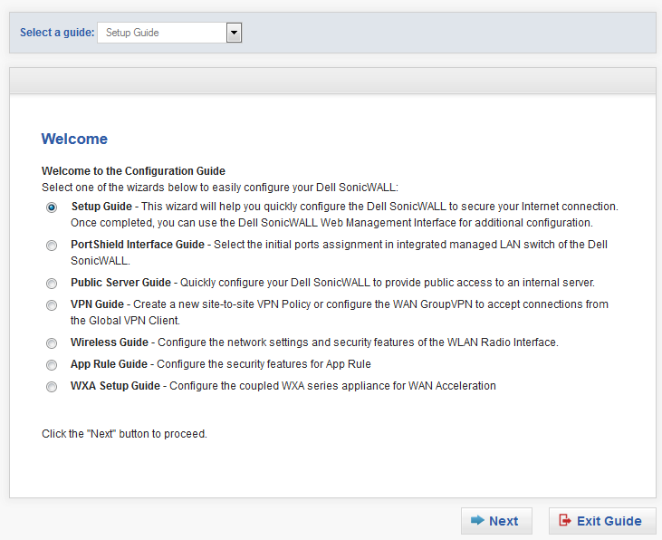
Click the link in To launch the Dell SonicWAlL Setup Wizard, click here. The Welcome dialog displays.
|
|
3
|
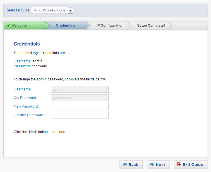
Click Next. The Credentials dialog displays.
|
|
|
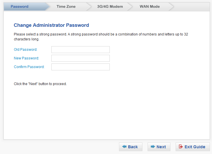
If the Old Password field is not dimmed, you need to enter password in it.
|
|
5
|
Click Next. A Running DHCP detection message displays.
|
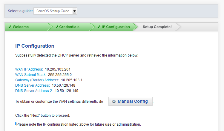
When the IP configuration of the DHCP server is detected, the Setup Guide populates the IP Configuration dialog with the IP information and displays the dialog.
|
6
|
Click Next. The Setup Complete! dialog displays.
|
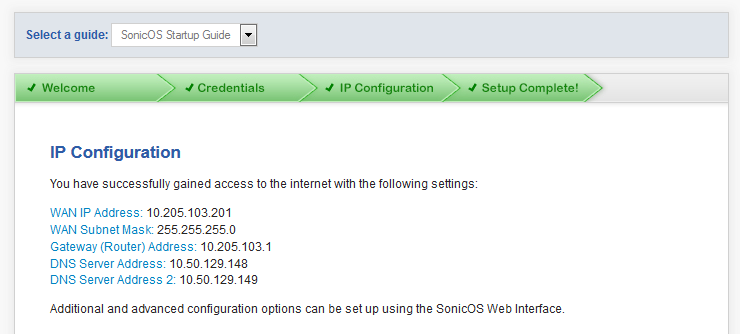
You now have internet access and basic settings for your appliance.
|
7
|
Click Done. A message displays saying you are being connected to a secure login page before the login page displays.
|
You can continue configuring your appliance by clicking Wizards in the upper right corner of the SonicOS management interface. A good place to start is the Setup Guide, which is different from the Initial Setup Guide.
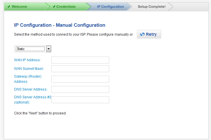
If you have not set up a WAN interface or want to customize the settings and clicked Manual Config, the IP Configuration – Manual Configuration dialog displays.
|
•
|
Static (default) – Use a Static IP address or a range of IP addresses for router-based connections. An IP address is a number that identifies each device on your network. An IP address consists of four numbers, separated by periods, ranging from 0 to 254 in value. Examples of IP addresses are 192.168.168.1, 10.0.0.1, or 216.217.36.130.
|
Every IP address on your network must be unique. Therefore, do not assign your Dell SonicWALL an IP address that is used by another device on your network.
Go to Static WAN Mode .
|
•
|
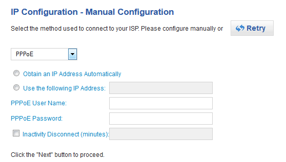
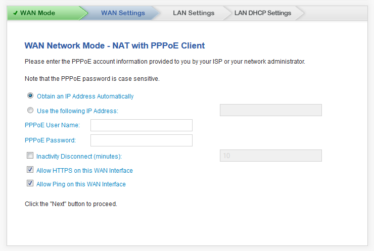
PPPoE – Use PPPoE for ISP client authentication software with DSL connections. Point-to-Point Protocol over Ethernet (PPPoE) is a widely-deployed solution to manage DSL and cable broadband services. PPPoE requires user name and password authentication to connect to the Internet.
|
Go to PPPoE WAN Mode .
|
•
|
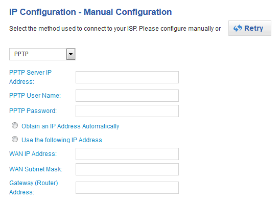
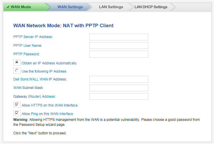
PPTP – Use PPTP for encrypted VPN connections. Point-to-Point Tunneling Protocol (PPTP) is used to tunnel Point to Point Protocol (PPP) through an IP network. PPTP requires Server IP address, user name and password authentication to connect to the Internet.
|
Go to PPTP WAN Mode .
The TZ Series and SOHO W Setup Guide helps you configure the following settings:
|
1
|
Click Wizard on the top-right corner of the SonicOS management interface.
|

The Welcome page displays.
|
3
|
Click Next. If you have a:
|

|
•
|
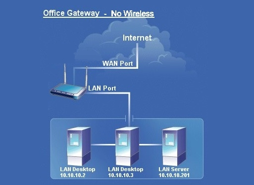
No Wireless (default) – The wireless radio is turned off.
|
|
•
|
Office Gateway – Provides secure access for both wired and wireless users.
|
|
2
|
Click Next. The Change Administrator Password page displays.
|
|
3
|
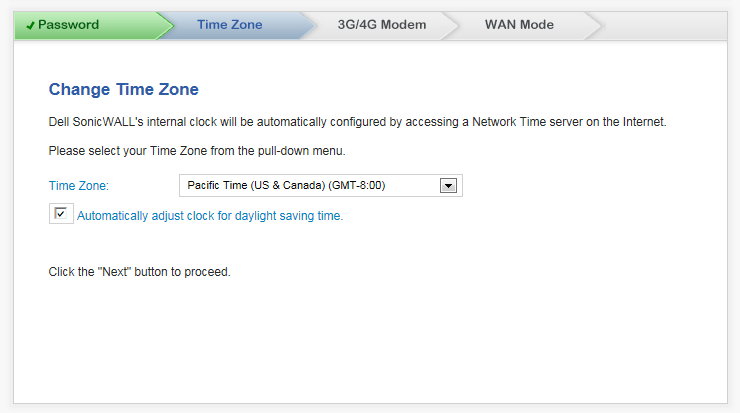
Click Next. The Time Zone page displays.
|
|
4
|
Select the appropriate Time Zone from the Time Zone drop-down menu. The SonicWALL’s internal clock is set automatically to the correct time for this time zone by a Network Time Server on the Internet.
|
|
5
|
Optionally, select Automatically adjust clock for daylight savings time. This is selected by default.
|
|
•
|
Office Gateway or Secure or Open Access Point, the page that displays depends on your appliance:
|
|
9
|
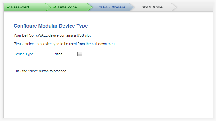
Click Next. The page that displays next depends on your device type selection:
|
|
4
|
Click Next. If you have a:
|
|
•
|
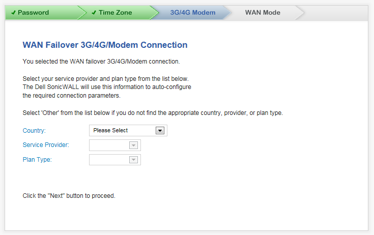
TZ wireless appliance, the WAN Failover 3G/4G Connection page displays; except for the name, this is the same as the WAN Failover 3G/4G/Modem Connection page
|
|
7
|
Click Next. The WAN Mode dialog displays.
|
|
1
|
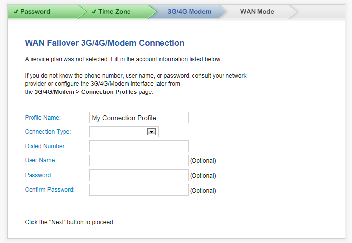
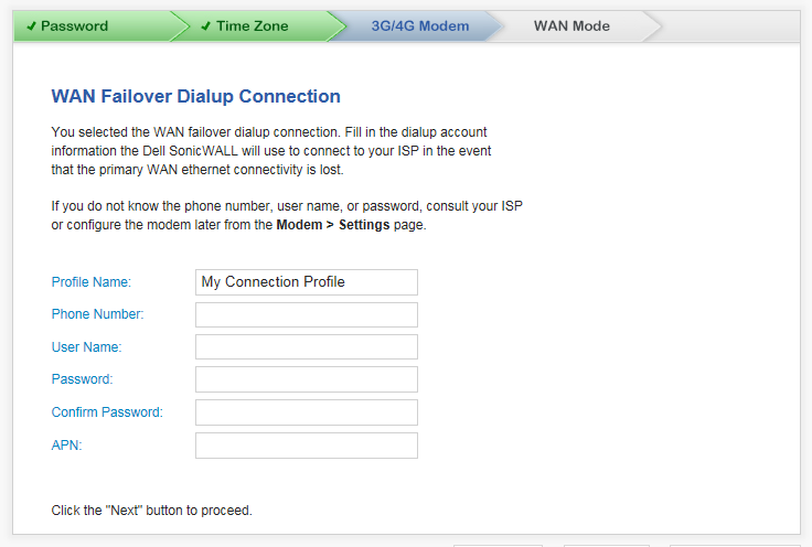
If you selected Other for Country, Service Provider, or Plan Type, the second page is not populated with information, and you must provide the required information:
|
|
•
|
Profile Name – Enter a friendly name for the profile in this field; the default is My Connection Profile.
|
|
•
|
Dialed Number – Enter the dialup number the appliance uses to connect to the internet in this field.
|
|
•
|
User Name (optional) – Enter your ISP user name in this field.
|
|
•
|
Password (optional) – Enter your ISP password in this field.
|
|
2
|
Click Next. The WAN Mode page displays.
|
|
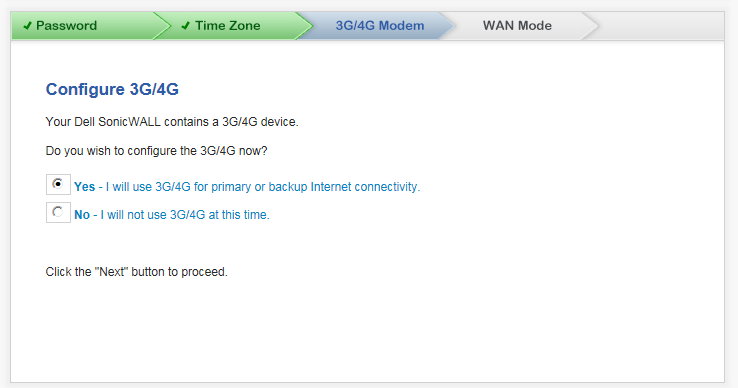
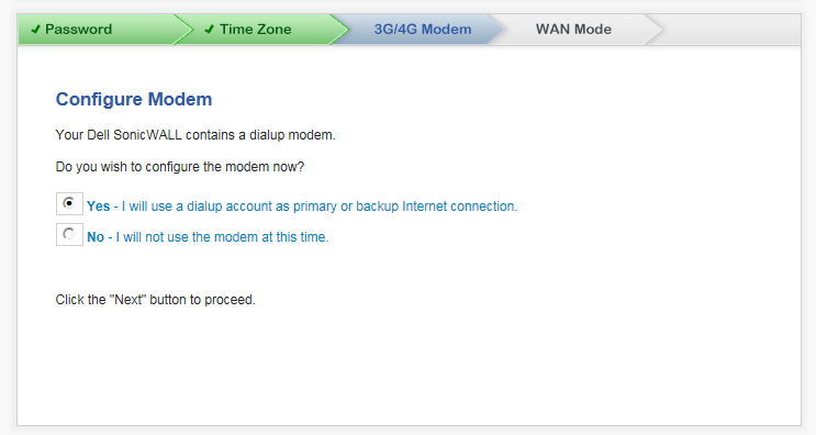
•
|
Yes – The 3G/4G Modem > WAN Failover Dialup Connection page displays.
|
|
•
|
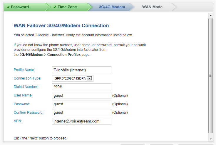
Profile Name – A friendly name for the profile; the default is My Connection Profile.
|
|
•
|
APN – Your ISP Access Point Name.
|
|
5
|
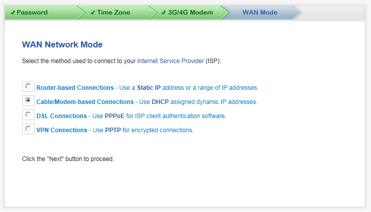
Click Next. The WAN Network Mode page displays.
|
|
•
|
Router-based Connections – Use a Static IP address or a range of IP addresses. – An IP address is a number that will identify each device on your network. An IP address consists of four numbers, separated by periods, ranging from 0 to 254 in value. Examples of IP addresses are 192.168.168.1, 10.0.0.1, or 216.217.36.130. This is the default for TZ Series wired and wireless appliances.
|
Every IP address on your network must be unique. Therefore, do not assign your Dell SonicWALL an IP address that is used by another device on your network.
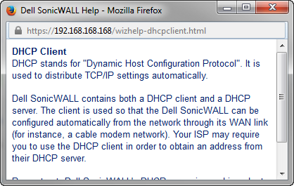
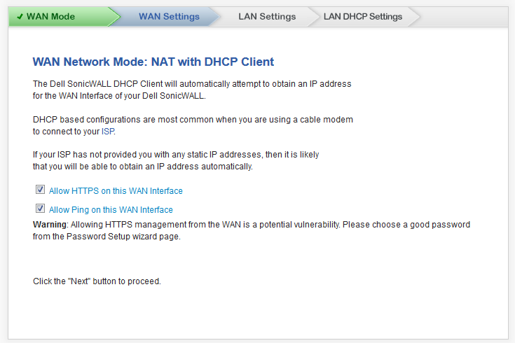
Dell SonicWALL appliances contain both a DHCP client and a DHCP server. The client is used so that the Dell SonicWALL can be configured automatically from the network through its WAN link (for instance, a cable modem network). Your ISP may require you to use the DHCP client to obtain an address from their DHCP server.
|
•
|
VPN Connections – Use PPTP for encrypted connections. – Point-to-Point Tunneling Protocol (PPTP) is used to tunnel Point to Point Protocol (PPP) through an IP network. PPTP requires Server IP address, user name and password authentication to connect to the Internet.
|
|
2
|
Click Next. What displays next depends on your WAN network mode selection.
|
|
•
|
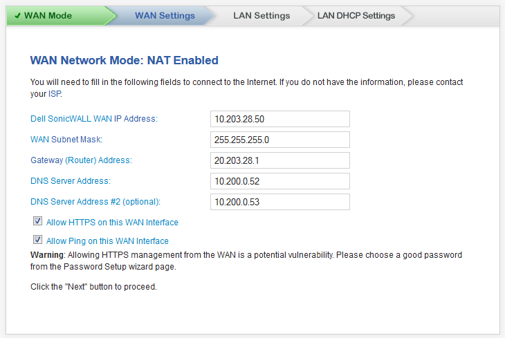
Dell SonicWALL WAN IP Address – An IP address is a number that identifies each device on your network. An IP address consists of four numbers, separated by periods, ranging from 0 to 254 in value. Examples of IP addresses are 192.168.168.1, 10.0.0.1, or 216.217.36.130.
|
Every IP address on your network must be unique. Therefore, do not assign your Dell SonicWALL an IP address used by another device on your network.
|
•
|
WAN Subnet Mask – The subnet mask defines which IP addresses are located on your local network and which IP addresses are located on the Internet. For example, if you assign your computer the IP address 192.168.168.200 and the subnet mask 255.255.255.0, then your computer will believe that all 192.168.168.X addresses are on the local network, and all other addresses are located on the Internet.
|
The WAN Subnet Mask should be assigned by your ISP. If you do not know your WAN Subnet Mask, use the subnet mask assigned to your computer or contact your ISP.
|
•
|
Gateway Router Address – The WAN gateway (router) address is the IP address of the router that bridges your network to the Internet. The WAN router may be attached directly to the Dell SonicWALL appliance's WAN port or indirectly through a cable or DSL modem.
|
The WAN Gateway (router) address must be in the same subnet as the Dell SonicWALL appliance WAN IP address. The WAN gateway (router) address often ends with the numbers .1 or .254. So, if your WAN IP address is 216.0.36.128, then your gateway might be 216.0.36.1 or 216.0.36.254. If you do not know your gateway address, contact your ISP.
|
4
|
Click NEXT. The page that displays next depends on the type of appliance:
|
|
3
|
Click NEXT. The page that displays next depends on the type of appliance:
|
|
7
|
Click NEXT. The LAN Settings page displays.
|
|
8
|
Click NEXT. The page that displays next depends on the type of appliance:
|
An IP address is a number that identifies each device on your network. An IP address consists of four numbers, separated by periods, ranging from 0 to 254 in value. Examples of IP addresses are 192.168.168.1, 10.0.0.1, or 216.217.36.130.
Every IP address on your network must be unique. Therefore, do not assign your Dell SonicWALL an IP address used by another device on your network.
The subnet mask defines which IP addresses are located on your local network and which IP addresses are located on the Internet. For example, if you assign your computer the IP address 192.168.168.200 and the subnet mask 255.255.255.0, then your computer believes that all 192.168.168.X addresses are on the local network, and all other addresses are located on the Internet.
The WAN subnet mask is assigned by your ISP. If you do not know your WAN Subnet Mask, use the subnet mask assigned to your computer or contact your ISP.
|
10
|
Click NEXT. The page that displays next depends on the type of appliance:
|
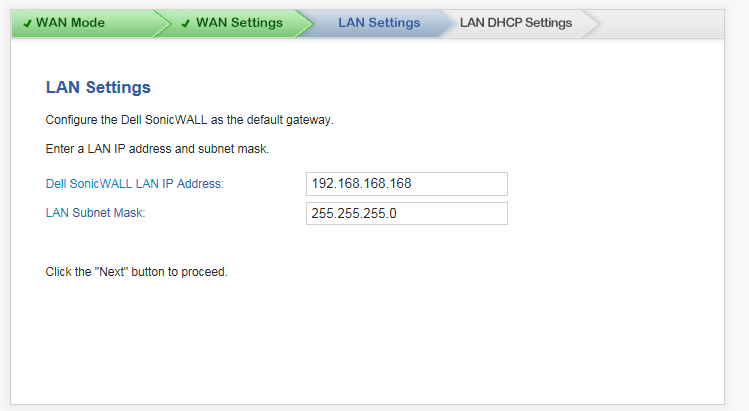
The Setup Wizard populates the LAN Settings fields automatically, based on the supplied settings.
|
•
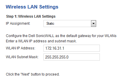
|
Dell SonicWALL LAN IP Address – The IP address of the Dell SonicWALL LAN. Every IP address on your network must be unique. Therefore, do not assign your Dell SonicWALL an IP address that is used by another device on your network.
|
|
•
|
LAN Subnet Mask – The subnet mask defines which IP addresses are located on your local network and which IP addresses are located on the Internet. For example, if you assign your computer the IP address 192.168.168.200 and the subnet mask 255.255.255.0, then your computer believes that all 192.168.168.X addresses are on the local network, and all other addresses are located on the Internet.
|
The LAN subnet mask defines the size of your local network. The LAN subnet mask 255.255.255.0 works for most networks.
|
2
|
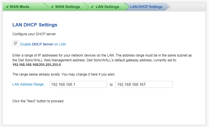
Click Next. The LAN DHCP Settings page displays.
|
|
1
|
Select Enable DHCP Server on LAN checkbox. This is checked by default.
|
DHCP (Dynamic Host Configuration Protocol) is used to distribute TCP/IP settings automatically. A DHCP server simplifies network address management and avoids the time-consuming task of configuring each computer's IP settings.
|
2
|
The Setup Wizard populates the LAN Address Range fields automatically. Verify the addresses are correct.
|
Enter a range of IP addresses for your network devices on the LAN. The address range must be in the same subnet as the Dell SonicWALL Web Management address. Dell SonicWALL's default gateway address is currently set according to the IP address that have been configured.
|
2
|
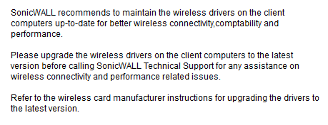
Click Next. An information message about maintaining up-to-date wireless drivers on your client computers displays.
|
|
3
|
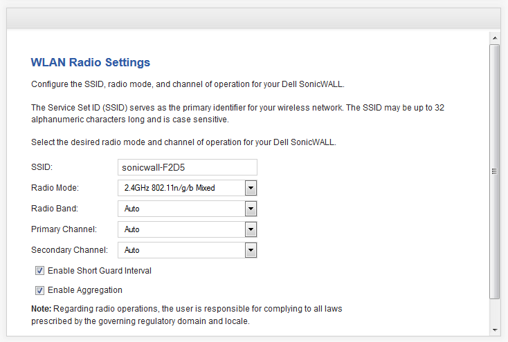
Click OK. The WLAN Radio Settings page displays.
|
|
1
|
Enter a SSID (Service Set ID) in the SSID field. The SSID serves as the primary identifier for your wireless network. You can specify up to 32 alphanumeric characters; the SSID is case sensitive. The appliance generates a default SSID; for example, sonicwall or sonicwall-F2DS.
|
|
•
|
Auto - Allows the appliance to automatically detect and set the optimal channel for wireless operation based on signal strength and integrity. Use Auto unless you have a specific reason to use or avoid specific channels.
|
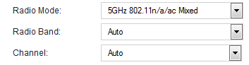
From the Radio Band drop-down menu, select the radio band for the 802.11a or 802.11ac radio:
|
•
|
Auto - Allows the appliance to automatically detect and set the optimal channel for wireless operation based on signal strength and integrity.
|
|
•
|
The Channel drop-down menu is set to Auto and cannot be changed.
|
|
•
|
Standard - 20 MHz Channel - Specifies that the 802.11ac radio uses only the standard 20 MHz channel. This is the default setting.
|
|
a
|
When this option is selected, from the Channel drop-down menu, select a single channel within the range of your regulatory domain. Selecting a specific a channel can also help with avoiding interference with other wireless networks in the area. For the available channels, see Table 166. The default channel is Channel 36 (5180MHz).
|
|
•
|
Wide - 40 MHz Channel - Specifies that the 802.11ac radio uses only the wide 40 MHz channel. When this option is selected, the Channel drop-down menu is displayed. See Step a above for selecting a channel.
|
|
•
|
Wide - 80 MHz Channel - Specifies that the 802.11n radio uses only the wide 80 MHz channel. When this option is selected, the Channel drop-down menu is displayed. See Step a above for selecting a channel.
|
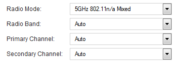
From the Radio Band drop-down menu, select the band for the 802.11n or 802.11ac radio:
|
•
|
Auto - Allows the appliance to automatically detect and set the optimal channel for wireless operation based on signal strength and integrity. This is the default setting.
|
|
•
|
The Primary Channel and Secondary Channel drop-down menus are set to Auto and cannot be changed.
|
|
•
|
Standard - 20 MHz Channel - Specifies that the 802.11n radio will use only the standard 20 MHz channel. When this option is selected, the Channel drop-down menu is displayed instead of the Primary Channel and Secondary Channel drop-down menus.
|
|
•
|
Standard Channel - By default, this is set to Auto, which allows the appliance to set the optimal channel based on signal strength and integrity. Optionally, you can select a single channel within the range of your regulatory domain. Selecting a specific a channel can also help with avoiding interference with other wireless networks in the area. The available channels are the same as for 802.11g in Step 4.
|
|
•
|
Wide - 40 MHz Channel - Specifies that the 802.11n radio will use only the wide 40 MHz channel. When this option is selected, the Primary Channel and Secondary Channel drop-down menus are displayed:
|
|
•
|
Primary Channel - By default, this is set to Channel 36 (5180MHz). Optionally, you can specify a specific another channel or Auto. The available channels are the same as for 802.11a in Step 4
|
|
•
|
Secondary Channel - The configuration of this drop-down menu is set to Auto regardless of the primary channel setting.
|
|
9
|
Optionally, select the Enable Short Guard Interval checkbox to specify a short guard interval of 400ns as opposed to the standard guard interval of 800ns. This setting is not selected by default.
|
A guard interval is a set amount of time between transmissions that is designed to ensure distinct transmissions do not interfere with one another. The guard interval introduces immunity to propagation delays, echoes, and reflections. An AP identifies any signal content received inside this interval as unwanted inter-symbol interference, and rejects that data. The guard interval is a pause in transmission intended to avoid data loss from interference or multipath delays.
The 802.11n standard specifies two guard intervals: 400ns (short) and 800ns (long). Enabling a short guard interval can decrease network overhead by reducing unnecessary idle time on each AP. A short guard interval of 400 nanoseconds (ns) will work in most office environments as distances between points of reflection, as well as between clients, are short. Most reflections will be received quickly. The shorter the guard interval, the more efficiency there is in the channel usage, but a shorter guard interval also increases the risk of interference
Some outdoor deployments, may, however, require a longer guard interval. The need for a long guard interval of 800 ns becomes more important as areas become larger, such as in warehouses and in outdoor environments, as reflections and echoes become more likely to continue after the short guard interval would be over.
Data over wireless networks are sent as a stream of packets known as data frames. Frame aggregation takes these packets and combines them into fewer, larger packets, thereby allowing an increase in overall performance. Frame aggregation was added to the 802.11n specification to allow for an additional increase in performance. Frame aggregation is a feature that only 802.11ac and 802.11n clients can take advantage of as legacy systems are not able to understand the new format of the larger packets.
|
|
TIP: The Enable Short Guard Interval and Enable aggregation options can slightly improve throughput. They both function best in optimum network conditions where users have strong signals with little interference. In networks that experience less than optimum conditions (interference, weak signals, and so on), these options may introduce transmission errors that eliminate any efficiency gains in throughput.
|
|
11
|
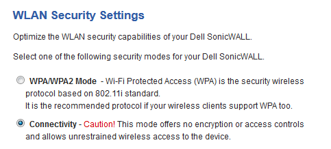
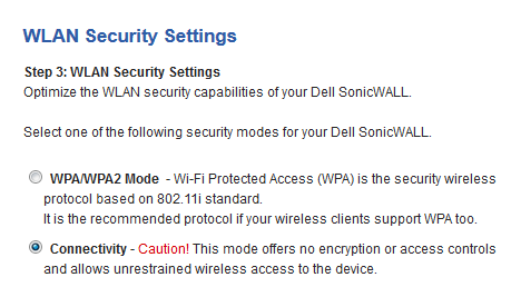
Click Next. The WLAN Security Settings page displays.
|
|
•
|
WPA/WPA2 Mode – Wi-Fi Protected Access (WPA) mode is the security wireless protocol based on the 802.11i standard. It is the recommended protocol if your wireless clients support WPA/WPA protocol also.
|
|
•
|
Connectivity (default) – This mode allows unrestrained wireless access to the device.
|
|
2
|
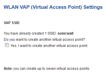
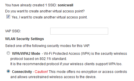
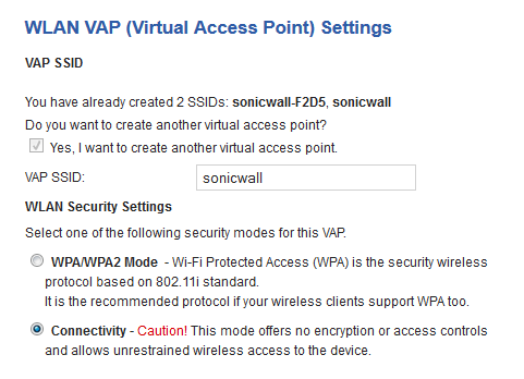
Click Next. The WLAN VAP (Virtual Access Point) Settings page displays.
|
|
•
|
WPA/WPA2 Mode – Wi-Fi Protected Access (WPA) mode is the security wireless protocol based on the 802.11i standard. It is the recommended protocol if your wireless clients support WPA/WPA protocol also.
|
|
•
|
Connectivity (default) – This mode allows unrestrained wireless access to the device.
|
|
5
|
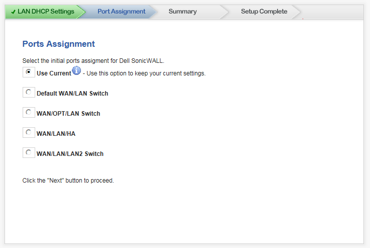
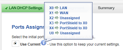
Click Next. The Ports Assignment page displays.
|
|
•
|
Use Current – This setting keeps your current settings. This option is selected by default.
|

|
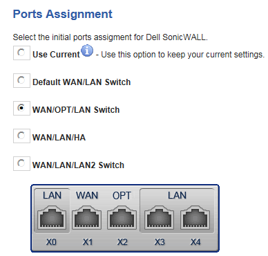
•
|
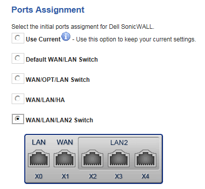
WAN/OPT/LAN Switch – This option displays the port configuration at the bottom of the page:
|
|
•
|
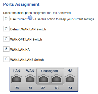
WAN/LAN/HA – This option displays the port configuration at the bottom of the page:
|
|
2
|
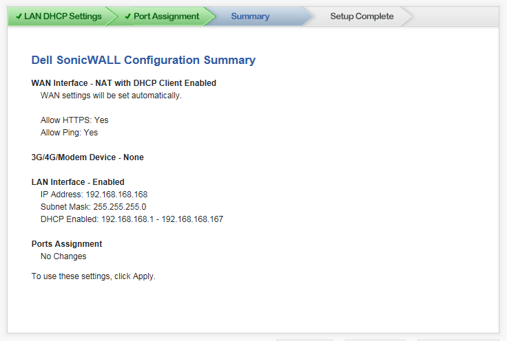
Click Next. The Summary page displays.
|
|
|
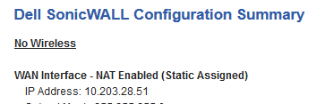
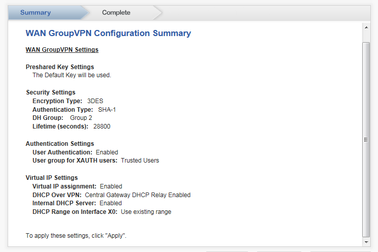
NOTE: What is displayed on the Dell SonicWALL Configuration Summary depends on the settings you entered. If you have configured a TZ Series wireless or SOHO W wireless appliance, but selected No Wireless on the Deployment Scenario page, No Wireless is displayed:
|
|
4
|
Click Apply. A message displays indicating the configuration is being updated:
|
After the configuration has updated, the Setup Complete dialog displays.

You use the PortShield Interface Guide to select the initial ports assignment in integrated managed LAN switch of the Dell SonicWALL appliance.
|
1
|
Click Wizards in the upper right corner of the SonicWALL management interface. The Wizard Welcome page displays.
|
|
3
|
Click Next. The Port Assignment dialog displays.
|
|
•
|
Use Current – This setting keeps your current settings. This option is selected by default.
|
|
•
|
WAN/OPT/LAN Switch – This option displays the port configuration at the bottom of the dialog:
|
|
•
|
WAN/LAN/HA – This option displays the port configuration at the bottom of the dialog:
|
|
2
|
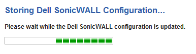
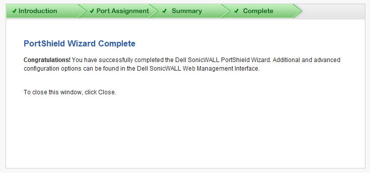
Click Apply. A message displays indicating the configuration is being updated:
|
After the configuration has updated, the Complete dialog displays.
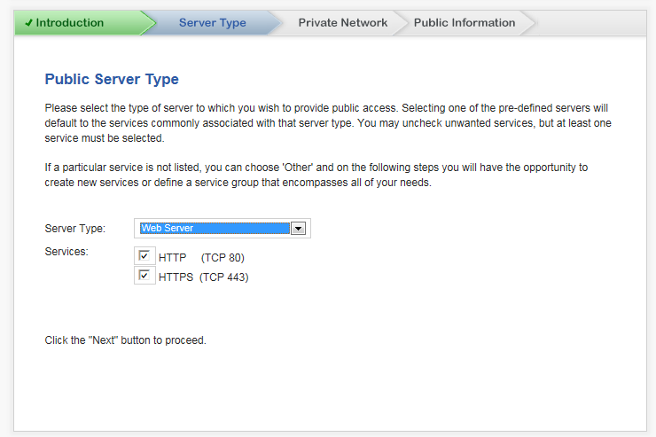
The Public Server Guide allows you to quickly configure your Dell SonicWALL appliance to provide public access to an internal server.
|
1
|
Click Wizards in the upper right corner of the SonicWALL management interface. The Wizard Welcome page displays.
|
|
3
|
Click Next. The Server Type dialog displays.
|
|
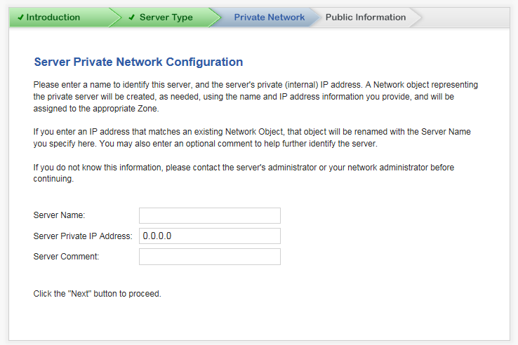
6
|
Click Next. The Private Network dialog displays.
|
|
10
|
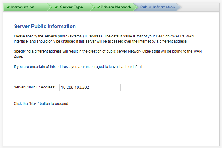
Click Next. The Public Information dialog displays.
|
|
12
|
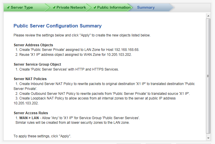
Click Next. The Summary dialog displays
|
|
14
|
Click Apply. A message displays indicating the configuration is being updated:
|
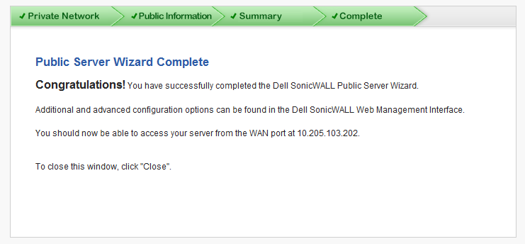
After the configuration has updated, the Complete dialog displays.
The VPN Guide steps you through creating a new site-to-site VPN Policy or configuring the WAN GroupVPN to accept connections from the Global VPN Client.
|
1
|
Click Wizards in the upper right corner of the SonicWALL management interface. The Wizard Welcome page displays.
|
|
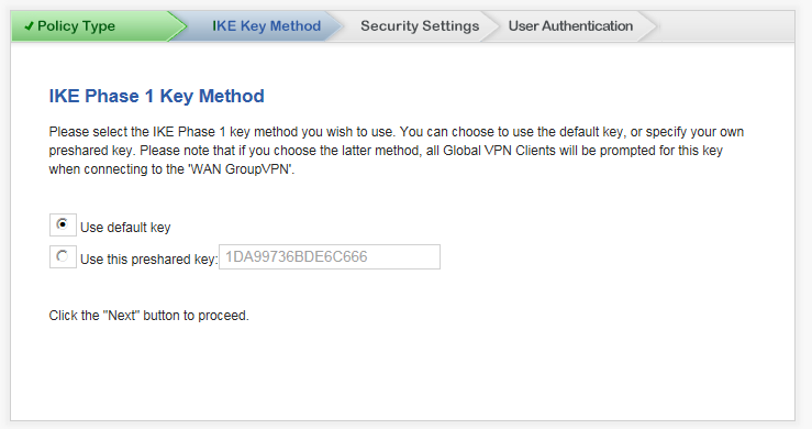
3
|
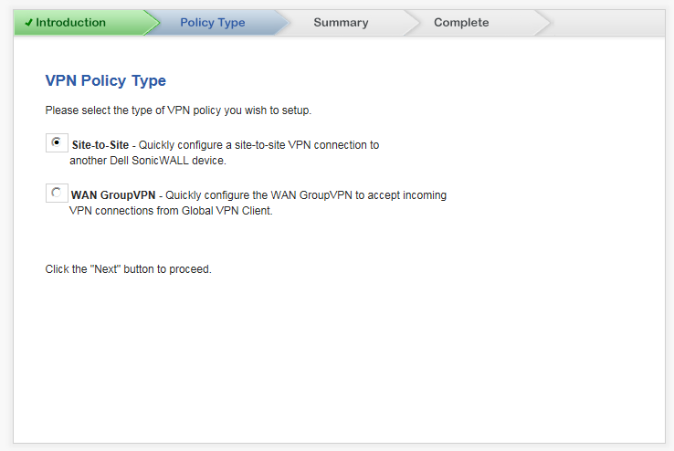
Click Next. The Policy Type dialog displays.
|
|
•
|
Site-to-Site – Configure a site-to-site VPN connection to another Dell SonicWALL device. This is the default selection.
|
|
•
|
WAN GroupVPN – Configure a WAN GroupVPN to accept incoming VPN connections from Global VPN Client.
|
|
5
|
Click Next. The dialog that displays depends on your choice of VPN policy type:
|
|
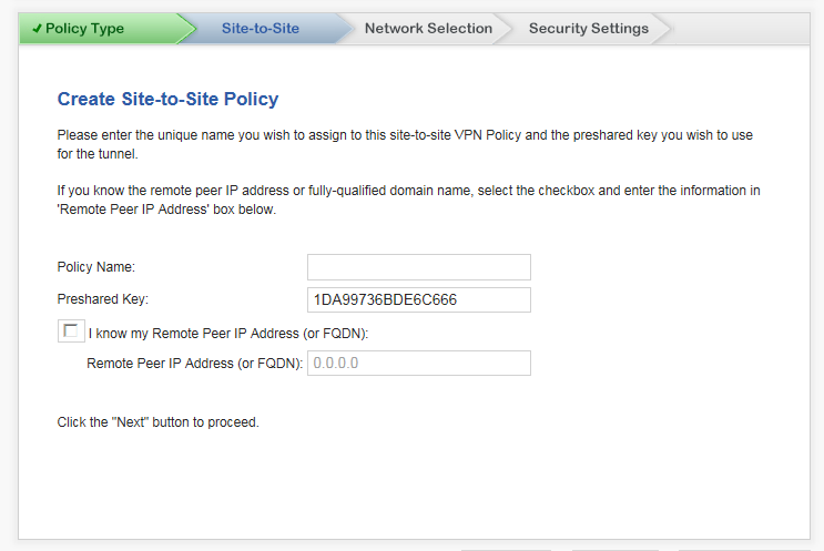
1
|
In the Policy Name field, enter a unique, friendly name to assign to this site-to-site VPN Policy.
|
|
2
|
In the Preshared Key field, enter the preshared key to use for the tunnel. The VPN Guide generates a default key.
|
|
4
|
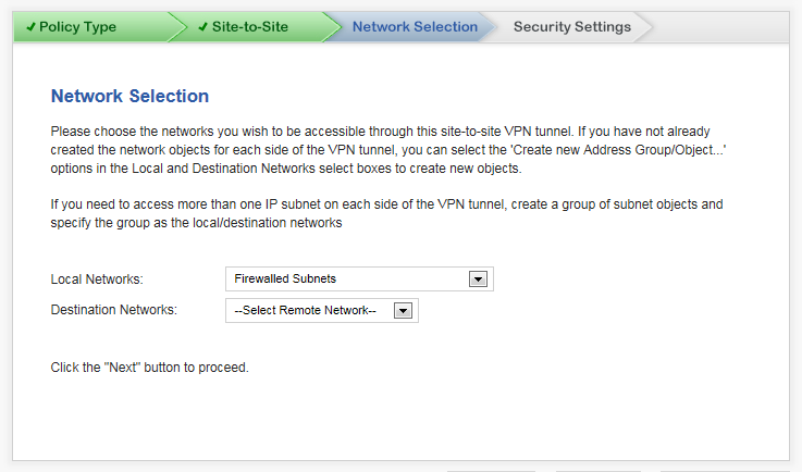
Click Next. The Network Selection dialog displays.
|
|
5
|
From the Local Networks drop-down menu, select the local networks to be accessible through this site-to-site VPN tunnel. The default is Firewalled Subnets.
|
|
6
|
From the Destination Networks drop-down menu, select the destination networks.
|
|
7
|
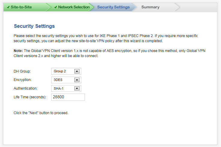
Click Next. The Security Settings dialog displays.
|
|
•
|
DH Group: The Diffie-Hellman (DH) group is the group of numbers used to create the key pair. Each subsequent group uses larger numbers to start with. The VPN Uses the DH group during IKE negotiation to create the key pair. You can choose:
|
|
•
|
Encryption: This is the method for encrypting data through the VPN Tunnel. The methods are listed in order of security. DES is the least secure and the and takes the least amount of time to encrypt and decrypt. AES-256 is the most secure and takes the longest time to encrypt and decrypt.The VPN uses this for all data through the tunnel.
|
You can choose: DES, 3DES (default), AES-128, AES-256, or AES-192.
|
•
|
Authentication: This is the hashing method used to authenticate the key, once it is exchanged during IKE negotiation. You can choose MD5 or SHA-1 (default), SHA-256, SHA-384, or SHA-512.
|
|
•
|
Life Time (seconds): This is the length of time the VPN tunnel stays open before needing to re-authenticate. The default is eight hours ( 28800).
|
|
9
|
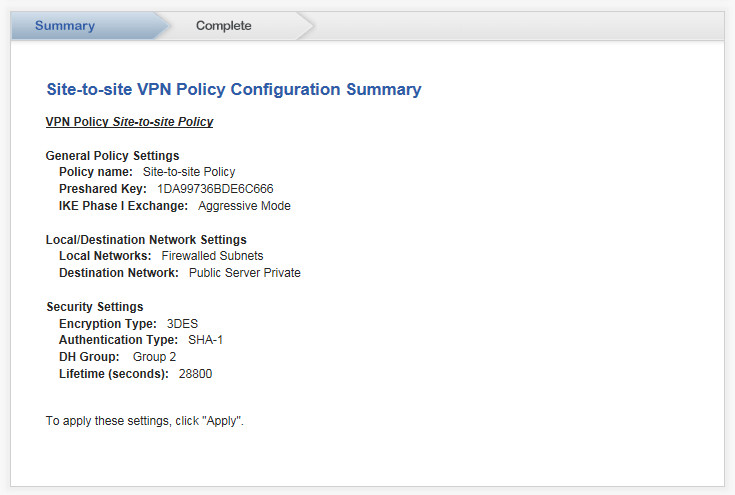
Click Next. The Summary diagram displays.
|
|
10
|
Click Apply. A message displays indicating the configuration is being updated:
|
After the configuration has updated, the Complete dialog displays.
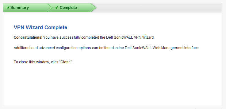
|
2
|
Click Next. The Security Settings dialog displays.
|
|
•
|
DH Group: The Diffie-Hellman (DH) group is the group of numbers used to create the key pair. Each subsequent group uses larger numbers to start with. The VPN Uses the DH group during IKE negotiation to create the key pair. You can choose:
|
|
•
|
Encryption: This is the method for encrypting data through the VPN Tunnel. The methods are listed in order of security. DES is the least secure and the and takes the least amount of time to encrypt and decrypt. AES-256 is the most secure and takes the longest time to encrypt and decrypt.The VPN uses this for all data through the tunnel.
|
You can choose: DES, 3DES (default), AES-128, AES-256, or AES-192.
|
•
|
Authentication: This is the hashing method used to authenticate the key, once it is exchanged during IKE negotiation. You can choose MD5 or SHA-1 (default), SHA-256, SHA-384, or SHA-512.
|
|
•
|
Life Time (seconds): This is the length of time the VPN tunnel stays open before needing to re-authenticate. The default is eight hours ( 28800).
|
|
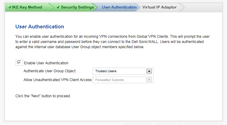
4
|
Click Next. The User Authentication dialog displays.
|
|
a
|
Select the Enable User Authentication checkbox. This is selected by default.
|
The user must enter a valid username and password before connecting to the Dell SonicWALL appliance. Users are authenticated against the internal user database User Group object members specified in the Authenticate User Group Object drop-down menu.
|
a
|
Unselect the Enable User Authentication checkbox, which is selected by default.
|
|
6
|
Click Next. The Virtual IP Adapter dialog displays.
|
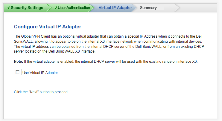
The Global VPN Client has an optional virtual adapter that can obtain a special IP Address when it connects to the Dell SonicWALL, thereby allowing it to appear to be on the internal X0 interface network when communicating with internal devices. The virtual IP address can be obtained from the internal DHCP server of the Dell SonicWALL appliance or from an existing DHCP server located on the Dell SonicWALL appliance’s X0 interface.
|
8
|
Click Next. The Summary dialog displays.
|
|
10
|
Click Apply. A message displays indicating the configuration is being updated:
|
After the configuration has updated, the Complete dialog displays.
The Wireless Guide steps you through configuring the network settings and security features of the WLAN radio interface.
|
1
|
Click Wizards in the upper right corner of the SonicWALL management interface. The Wizard Welcome page displays.
|
|
3
|
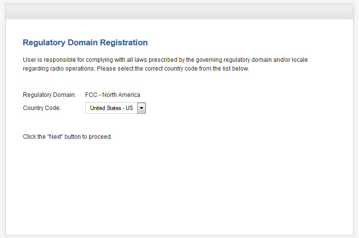
Click Next. The Regulatory Domain Registration page displays.
|
|
2
|
Click Next. An information message about maintaining up-to-date wireless drivers on your client computers displays.
|
|
3
|
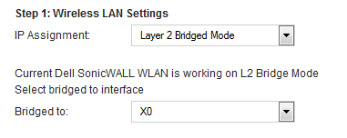
Click OK. The Wireless LAN Settings page displays.
|
|
3
|
Click Next. A message regarding keeping the wireless drivers on client computers up to date displays.
|
|
4
|
Click OK. The WLAN Radio Settings page displays.
|
|
1
|
Enter a SSID (Service Set ID) in the SSID field. The SSID serves as the primary identifier for your wireless network. You can specify up to 32 alphanumeric characters; the SSID is case sensitive. The appliance generates a default SSID; for example, sonicwall or sonicwall-F2DS.
|
|
•
|
Auto - Allows the appliance to automatically detect and set the optimal channel for wireless operation based on signal strength and integrity. Use Auto unless you have a specific reason to use or avoid specific channels.
|
From the Radio Band drop-down menu, select the radio band for the 802.11a or 802.11ac radio:
|
•
|
Auto - Allows the appliance to automatically detect and set the optimal channel for wireless operation based on signal strength and integrity.
|
|
•
|
The Channel drop-down menu is set to Auto and cannot be changed.
|
|
•
|
Standard - 20 MHz Channel - Specifies that the 802.11ac radio uses only the standard 20 MHz channel. This is the default setting.
|
|
a
|
When this option is selected, from the Channel drop-down menu, select a single channel within the range of your regulatory domain. Selecting a specific a channel can also help with avoiding interference with other wireless networks in the area. For the available channels, see Table 166 in WLAN Radio Settings . The default channel is Channel 36 (5180MHz).
|
|
•
|
Wide - 40 MHz Channel - Specifies that the 802.11ac radio uses only the wide 40 MHz channel. When this option is selected, the Channel drop-down menu is displayed. See Step a above for selecting a channel.
|
|
•
|
Wide - 80 MHz Channel - Specifies that the 802.11n radio uses only the wide 80 MHz channel. When this option is selected, the Channel drop-down menu is displayed. See Step a above for selecting a channel.
|
From the Radio Band drop-down menu, select the band for the 802.11n or 802.11ac radio:
|
•
|
Auto - Allows the appliance to automatically detect and set the optimal channel for wireless operation based on signal strength and integrity. This is the default setting.
|
|
•
|
The Primary Channel and Secondary Channel drop-down menus are set to Auto and cannot be changed.
|
|
•
|
Standard - 20 MHz Channel - Specifies that the 802.11n radio will use only the standard 20 MHz channel. When this option is selected, the Channel drop-down menu is displayed instead of the Primary Channel and Secondary Channel drop-down menus.
|
|
•
|
Standard Channel - By default, this is set to Auto, which allows the appliance to set the optimal channel based on signal strength and integrity. Optionally, you can select a single channel within the range of your regulatory domain. Selecting a specific a channel can also help with avoiding interference with other wireless networks in the area. The available channels are the same as for 802.11g in Step 4.
|
|
•
|
Wide - 40 MHz Channel - Specifies that the 802.11n radio will use only the wide 40 MHz channel. When this option is selected, the Primary Channel and Secondary Channel drop-down menus are displayed:
|
|
•
|
Primary Channel - By default, this is set to Channel 36 (5180MHz). Optionally, you can specify a specific another channel or Auto. The available channels are the same as for 802.11a in Step 4
|
|
•
|
Secondary Channel - The configuration of this drop-down menu is set to Auto regardless of the primary channel setting.
|
|
9
|
Optionally, select the Enable Short Guard Interval checkbox to specify a short guard interval of 400ns as opposed to the standard guard interval of 800ns. This setting is selected by default. For information about the guard interval, see WLAN Radio Settings .
|
|
|
TIP: The Enable Short Guard Interval and Enable aggregation options can slightly improve throughput. They both function best in optimum network conditions where users have strong signals with little interference. In networks that experience less than optimum conditions (interference, weak signals, and so on), these options may introduce transmission errors that eliminate any efficiency gains in throughput.
|
|
11
|
Click Next. The WLAN Security Settings page displays.
|
|
•
|
WPA/WPA2 Mode – Wi-Fi Protected Access (WPA) mode is the security wireless protocol based on the 802.11i standard. It is the recommended protocol if your wireless clients support WPA/WPA protocol also.
|
|
•
|
Connectivity (default) – This mode allows unrestrained wireless access to the device.
|
|
2
|
Click Next. What page displays depends on the security mode you selected.
|

|
1
|
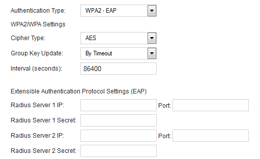
From the Authentication Type drop-down menu, select the encryption mode. The options that display depend on the mode you select.
|
|
2
|
From the Cipher Type drop-down menu, select:
|
|
3
|
From the Group Key Update drop-down menu select either:
|
|
•
|
Disabled; the Interval field does not display.
|
|
4
|
In the Interval (seconds) field, enter the time until timeout. The default is 86400.
|
|
6
|
In the Passphrase field, enter the passphrase from which the key is generated.
|
|
7
|
Click Next. The WLAN VAP (Virtual Access Point Settings page displays.
|
|
9
|
The Passphrase field is replaced by the Extensible Authentication Protocol Settings (EAP) fields.
|
|
10
|
In the Radius Server 1 IP and Port fields, enter the IP address and port number for your primary RADIUS server.
|
|
11
|
In the Radius Server 1 Secret field, enter the password for access to Radius Server
|
|
12
|
Optionally, in the Radius Server 2 IP and Port fields, enter the IP address and port number for your secondary RADIUS server, if you have one.
|
|
13
|
Optionally, in the Radius Server 2 Secret field, enter the password for access to Radius Server
|
|
14
|
Click Next. If you selected an EAP mode, a message about updating the firewall access rule is displayed.
|
|
15
|
Click OK. The WLAN VAP (Virtual Access Point Settings page displays.
|
|
2
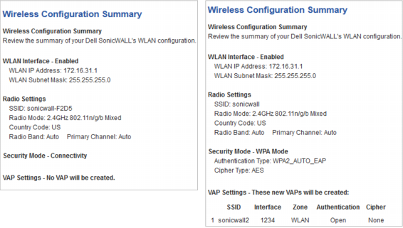
|
Click Next. The Wireless Configuration Summary page displays.
|
|
•
|
WPA/WPA2 Mode – Wi-Fi Protected Access (WPA) mode is the security wireless protocol based on the 802.11i standard. It is the recommended protocol if your wireless clients support WPA/WPA protocol also.
|
|
•
|
Connectivity (default) – This mode allows unrestrained wireless access to the device.
|
|
5
|
Click Next. The WLAN VAP (Virtual Access Point) Settings > WLAN Subnet and Zone page displays.
|
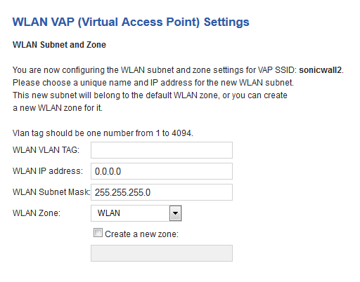
This new zone is used instead of any zone specified from the WLAN Zone drop-down menu.
|
6
|
Click Next. The WLAN VAP (Virtual Access Point) Settings page displays again.
|
|
c
|
Click Next until you reach the Wireless Configuration Summary page.
|
|
2
|
Click Apply. A message displays indicating the configuration is being updated:
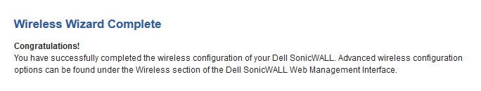
|
After the configuration has updated, the Wireless Wizard Complete dialog displays.
The App Rule Guide steps you through configuring the security features for App Rule.
|
1
|
Click Wizards in the upper right corner of the SonicWALL management interface. The Wizard Welcome page displays.
|
|
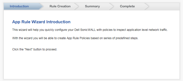
3
|
Click Next. The App Rule Wizard Introduction dialog displays, which describes the purpose of the App Rule Guide.
|
|
4
|
Click Next. The Rule Creation dialog displays.
|

|
6
|
Click Next. The dialog that displays depends on your choice of policy type:
|
|
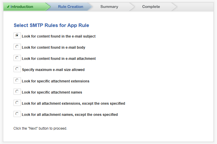
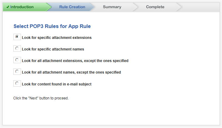
2
|
Click Next. The dialog that displays depends on the SMTP rule you selected:
|
To modify an entry in the List table:
To delete all entries in the List table, click the Remove All button.
To delete an entry in the List table:
|
|
|
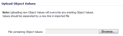
1
|
Click the Browse button to locate the desired file.
|
|
|
5
|
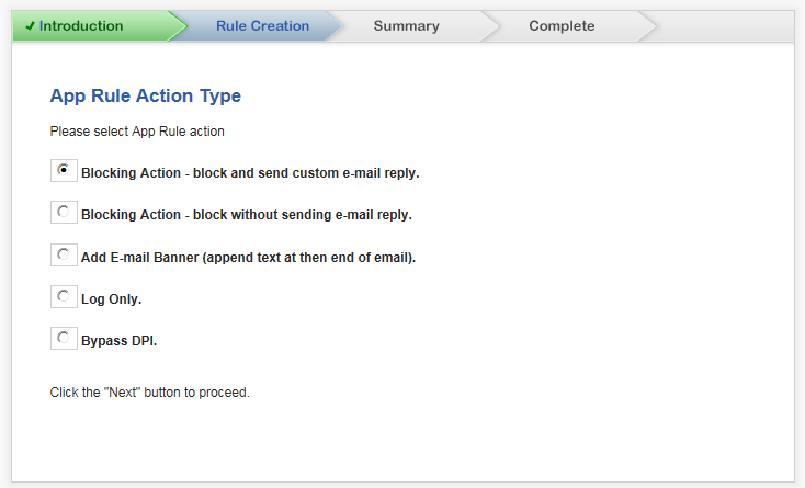
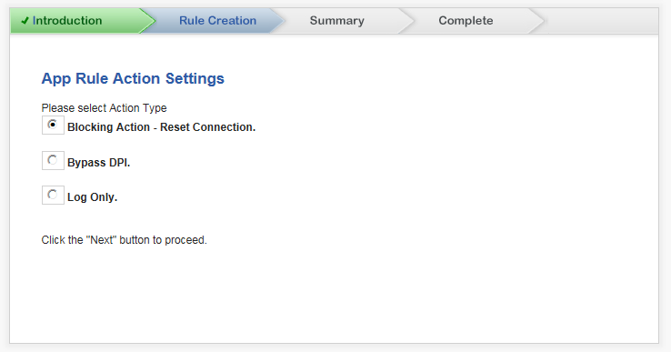
Click Next. the Rule Creation — App Rule Action Type dialog displays.
|
|
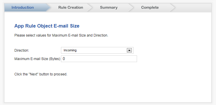
2
|
Click Next. The dialog that displays depends on the type of action selected:
|
|
2
|
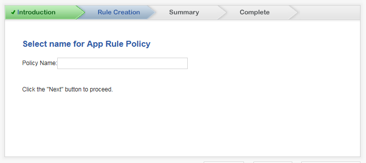
Click Next. The Rule Creation — Select name for App Rule Policy dialog displays.
|
|
2
|
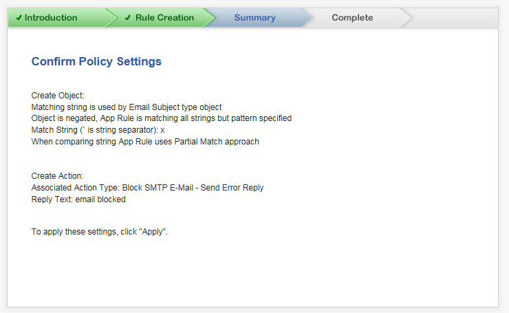
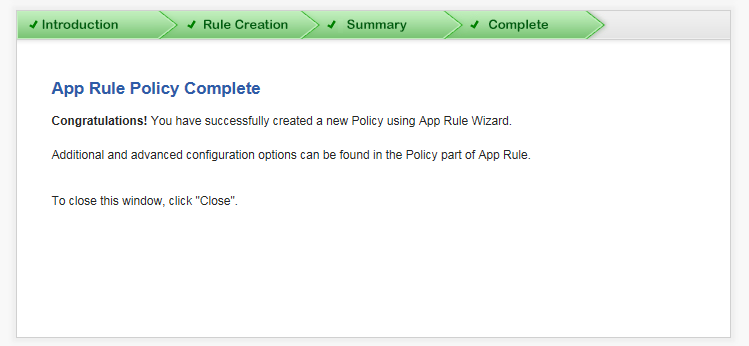
Click Next. The Summary page displays.
|
|
3
|
Click Apply. A message displays indicating the configuration is being updated:
|
After the configuration has updated, the Complete dialog displays.
|
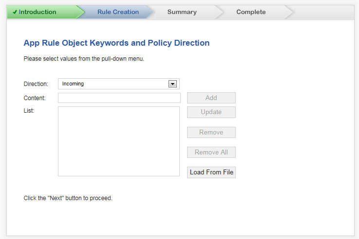
2
|
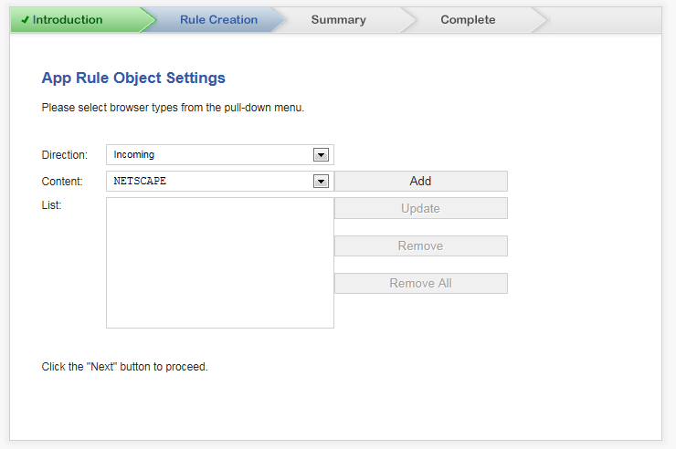
Click Next. The Rule Creation — App Rule Object Keywords and Policy Direction dialog displays.
|
To modify an entry in the List table:
To delete all entries in the List table, click the Remove All button.
To delete an entry in the List table:
|
|
|
1
|
Click the Browse button to locate the desired file.
|
|
|
5
|
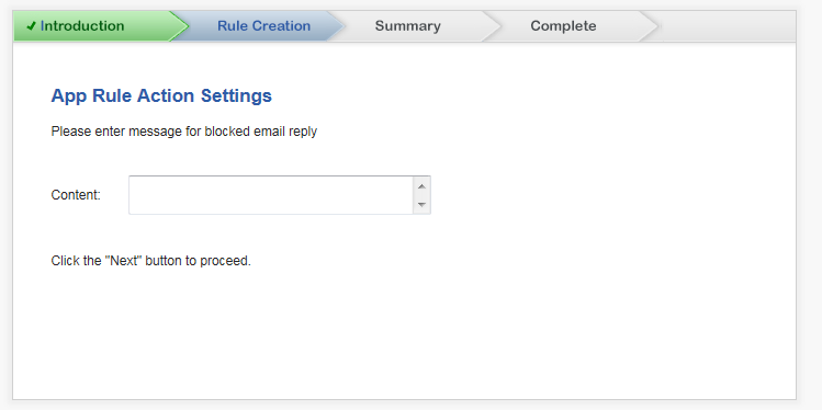
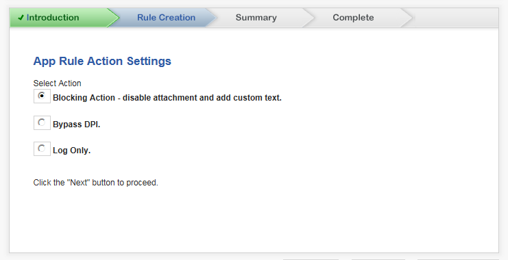
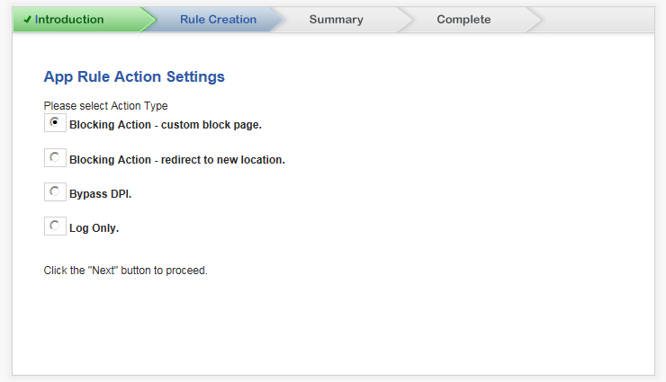
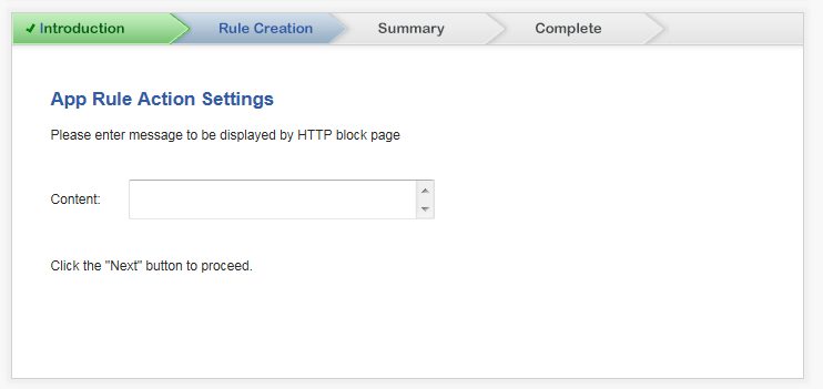
Click Next. the Rule Creation — App Rule Action Settings dialog displays.
|
|
2
|
Click Next. The dialog that displays depends on the type of action selected:
|
|
2
|
Click Next. The Rule Creation — Select name for App Rule Policy dialog displays.
|
|
2
|
Click Next. The Summary page displays.
|
|
3
|
Click Apply. A message displays indicating the configuration is being updated:
|
After the configuration has updated, the Complete dialog displays.
|
2
|
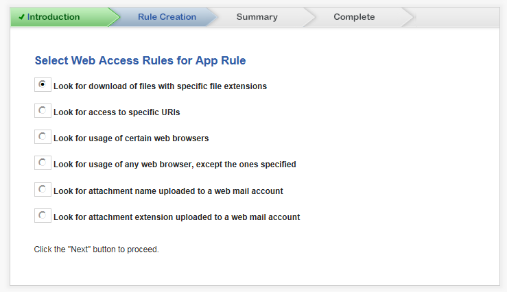
Click Next. The dialog that displays depends of the rule selected:
|
|
•
|
MSIE (Microsoft Internet Explorer)
|
|
•
|
Safari (does not operate on Windows platforms)
|
To modify an entry in the List table:
To delete all entries in the List table, click the Remove All button.
To delete an entry in the List table:
To modify an entry in the List table:
To delete all entries in the List table, click the Remove All button.
To delete an entry in the List table:
|
5
|
Click Next. The dialog that displays depends on your Access Rule selection on the Rule Creation — Select Web Access Rules for App Rule dialog:
|
|
2
|
Click Next. The dialog that displays depends on the type of action selected:
|
|
2
|
Click Next. The Rule Creation — Select name for App Rule Policy dialog displays.
|
|
2
|
Click Next. The Summary page displays.
|
|
3
|
Click Apply. A message displays indicating the configuration is being updated:
|
After the configuration has updated, the Complete dialog displays.
|
2
|
Click Next. The Rule Creation — App Rule Object Keywords and Policy Direction dialog displays.
|
|
|
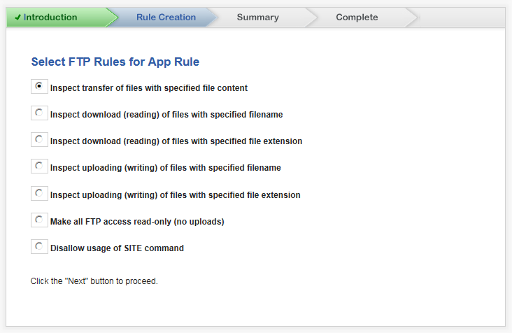
NOTE: If you selected an FTP rule of Make all FTP access read-only (no uploads) or Disallow usage of SITE command, the Direction drop-down menu is the only option available. After making your selection, go to Step 7.
|
To modify an entry in the List table:
To delete all entries in the List table, click the Remove All button.
To delete an entry in the List table:
|
|
|
1
|
Click the Browse button to locate the desired file.
|
|
|
7
|
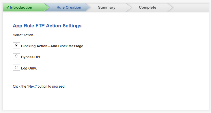
Click Next. The Rule Creation — App Rule Action Settings dialog displays.
|
|
|
NOTE: If you selected an FTP rule of Make all FTP access read-only (no uploads) or Disallow usage of SITE command, the Direction drop-down menu is the only option available, and it cannot be unselected.
If you selected the FTP rule, Inspect transfer of files with specified file content, this option is Blocking Action - Reset Connection (default).
|
|
9
|
Click Next. The Rule Creation — Select name for App Rule Policy dialog displays.
|
|
2
|
Click Next. The Summary page displays.
|
|
3
|
Click Apply. A message displays indicating the configuration is being updated:
|
After the configuration has updated, the Complete dialog displays.
The WXA Setup Guide configures the coupled WXA series appliance for WAN Acceleration.
For information about WAN Acceleration, WXA series appliances, and how to configure the WXA series appliance to work with your TZ Series wired and wireless appliances or you SOHO W wireless appliance, see the Dell SonicWALL WXA Clustering 1.3 Administration Guide and the most current Dell SonicWALL WXA for SonicsOS 6.2 Administration Guide.