|
An interface created on the Network > Interface page and bound to a tunnel policy. The interface is configured as the egress interface of a route entry or a SonicOS App that actively sends out packets such as Net Monitor Policy, Syslog policy. When SonicOS sends a packet out over the VPN Tunnel, logically it's the same as sending the packet over a physical interface, except the packet is encrypted. |
Route Based VPN configuration is a two-step process:
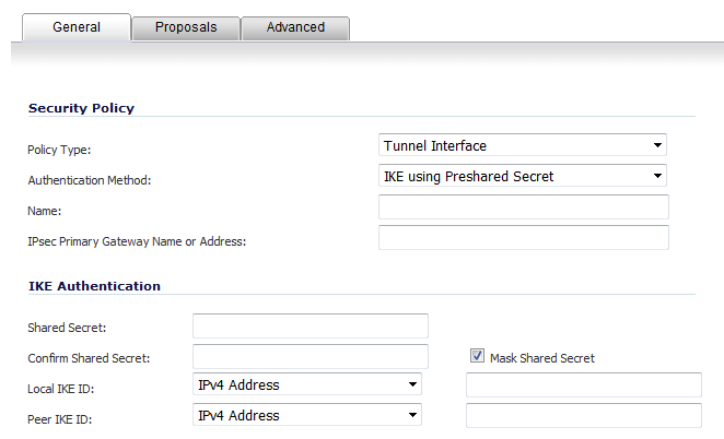
The Tunnel Interface is created when a Policy of type Tunnel Interface is added for the remote gateway. The Tunnel Interface must be bound to a physical interface, and the IP address of that physical interface is used as the source address of the tunneled packet.
|
1
|
Navigate to VPN > Settings.
|
|
2
|
|
3
|
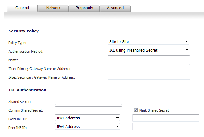
The IPsec Secondary Gateway name or Address field on the General tab and the Network tab are removed.
|
4
|
Enter a friendly name in the Name field.
|
|
5
|
|
6
|
|
7
|
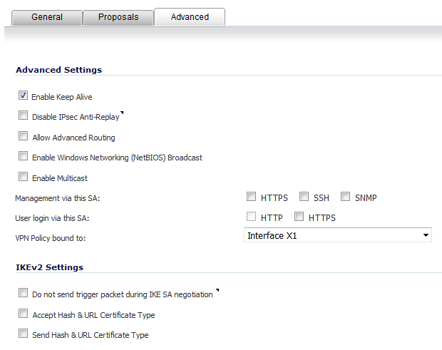
Click the Advanced tab to configure the advanced properties for the Tunnel Interface. By default, Enable Keep Alive is enabled.
|
|
•
|
Disable IPsec Anti-Replay - Disables anti-replay, which is a form of partial sequence integrity that detects the arrival of duplicate IP datagrams (within a constrained window).
|
|
•
|
Enable Windows Networking (NetBIOS) Broadcast - Allows access to remote network resources by browsing the Windows® Network Neighborhood.
|
|
•
|
Enable Multicast - Allows multicast traffic through the VPN tunnel.
|
|
•
|
Permit Acceleration - Enables redirection of traffic matching this policy to the WAN Acceleration (WXA) appliance.
|
|
•
|
Management via this SA - Allows remote users to log in to manage the firewall through the VPN tunnel. Select one or more: HTTPS, SSH, SNMP.
|
|
•
|
|
•
|
VPN Policy bound to - Sets the interface the Tunnel Interface is bound to. This is Interface X1 by default.
|
|
IMPORTANT: Two different WAN interfaces cannot be selected from the VPN Policy bound to drop-down menu if the VPN Gateway IP address is the same for both.
|
|
9
|
|
•
|
The Do not send trigger packet during IKE SA negotiation checkbox is not selected by default and should be selected only when required for interoperability if the peer cannot handle trigger packets.
|
The term Trigger Packet refers to the use of initial Traffic Selector payloads populated with the IP addresses from the packet that caused SA negotiation to begin. It is recommended practice to include Trigger Packets to assist the IKEv2 Responder in selecting the correct protected IP address ranges from its Security Policy Database. Not all implementations support this feature, so it may be appropriate to disable the inclusion of Trigger Packets to some IKE peers.
|
•
|
Accept Hash & URL Certificate Type – The firewall sends an HTTP_CERT_LOOKUP_SUPPORTED message to the peer device. If the peer device replies by sending a Hash and URL of X.509c certificate, the firewall can authenticate and establish a tunnel between the two devices.
|
|
•
|
Send Hash & URL Certificate Type – The firewall, on receiving an HTTP_CERT_LOOKUP_SUPPORTED message, sends a Hash and URL of X.509c certificate to the requestor.
|
|
10
|
Click OK.
|
After you have successfully added a Tunnel Interface, you may then create a Static Route.
|
1
|
Navigate to Network > Routing > Route Policies.
|
|
2
|
|
3
|
Select a tunnel interface from the Interface drop-down menu, which lists all available tunnel interfaces.
|
|
NOTE: If the Auto-add Access Rule option is selected, firewall rules are automatically added and traffic is allowed between the configured networks using tunnel interface.
|
|
5
|
Click OK.
|