|
•
|
|
1
|
In External Collector Settings, select the Send AppFlow and Real-Time Data To External Collector checkbox.
|
|
2
|
|
3
|
Specify the External Collector’s IP address in the provided field.
|
|
4
|
For the Source IP to Use for Collector on a VPN Tunnel, specify the source IP if the external collector must be reached by a VPN tunnel. Note that this step is optional.
|
|
5
|
Specify the External Collector’s UDP port number in the provided field. The default port is 2055.
|
|
6
|
In the Connection Report Settings and Report Connections, select the Interface-based checkbox. Once enabled, the flows reported are based on the initiator or responder interface. Note that this step is optional.
|
|
7
|
In the Connection Report Settings and Report Connections, select the Firewall/App Rules-based checkbox. Once enabled, the flows reported are based on already existing firewall rules. Note that this step is optional, but is required if flow reporting is done on selected interfaces.
|
|
8
|
Note that Netflow version-9 uses templates that must be known to an external collector before sending data. In External Collector Settings and Actions, click the Generate ALL Templates button to begin generating templates.
|
|
1
|
In External Collector Settings, select the Send AppFlow and Real-Time Data To External Collector checkbox.
|
|
2
|
|
3
|
Specify the External Collector’s IP address in the provided field.
|
|
4
|
For the Source IP to Use for Collector on a VPN Tunnel, specify the source IP if the external collector must be reached by a VPN tunnel. Note that this step is optional.
|
|
5
|
Specify the External Collector’s UDP port number in the provided field. The default port is 2055.
|
|
6
|
In the Connection Report Settings and Report Connections, select the Interface-based checkbox. Once enabled, the flows reported are based on the initiator or responder interface. Note that this step is optional.
|
|
7
|
In the Connection Report Settings and Report Connections, select the Firewall/App Rules-based checkbox. Once enabled, the flows reported are based on already existing firewall rules. Note that this step is optional, but is required if flow reporting is done on selected interfaces.
|
Note that IPFIX uses templates that must be known to an external collector before sending data. In External Collector Settings and Actions, click the Generate ALL Templates button to begin generating templates. IPFIX with Extensions Configuration Procedures
|
1
|
In External Collector Settings, select the Send AppFlow and Real-Time Data To External Collector checkbox.
|
|
2
|
|
3
|
Specify the External Collector’s IP address in the provided field.
|
|
4
|
For the Source IP to Use for Collector on a VPN Tunnel, specify the source IP if the external collector must be reached by a VPN tunnel.
|
|
5
|
Specify the External Collector’s UDP port number in the provided field. The default port is 2055.
|
|
6
|
Optionally, in the Connection Report Settings and Report Connections, select the Interface-based checkbox. Once enabled, the flows reported are based on the initiator or responder interface.
|
|
7
|
In the Connection Report Settings and Report Connections, select the Firewall/App Rules-based checkbox. Once enabled, the flows reported are based on already existing firewall rules. Note that this step is optional, but is required if flow reporting is done on selected interfaces.
|
|
8
|
Note that IPFIX uses templates that must be known to an external collector before sending data. Click the Generate ALL Templates button to begin generating templates.
|
|
9
|
Enable the option to Send static flows at regular intervals by selecting the checkbox. After enabling this option, click the Generate Static Flows button.
|
|
10
|
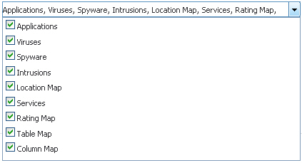
Select the tables you wish to receive static flows for from the Send Static AppFlow For Following Tables drop-down list.
|
|
11
|
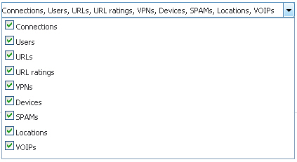
Select the tables you wish to receive dynamic flows for from the Send Dynamic AppFlow For Following Tables drop-down list.
|
|
12
|
Select any additional reports to be generated to a flow from the Include Following Additional Reports via IPFIX drop-down list.
|

|
1
|
In Visualization Dashboard Settings and Collector To User For AppFlow Monitor Page, select the AppFlow Server checkbox.
|
|
2
|
In AppFlow Server Settings, enable the Send AppFlow To SonicWALL AppFlow Server checkbox to enable flows to be reported to an external flow collector.
|
|
3
|
In External Collector Settings, select the Send AppFlow and Real-Time Data To External Collector checkbox.
|
|
4
|
|
5
|
Specify the External Collector’s IP address in the provided field.
|
|
6
|
For the Source IP to Use for Collector on a VPN Tunnel, specify the source IP if the external collector must be reached by a VPN tunnel.
|
|
7
|
Specify the External Collector’s UDP port number in the provided field. The default port is 2055.
|
|
8
|
In the Connection Report Settings and Report Connections, select the Interface-based checkbox. Once enabled, the flows reported are based on the initiator or responder interface. Note that this step is optional.
|
|
9
|
In the Connection Report Settings and Report Connections, select the Firewall/App Rules-based checkbox. Once enabled, the flows reported are based on already existing firewall rules. Note that this step is optional, but is required if flow reporting is done on selected interfaces.
|
|
10
|
|
11
|
Next, navigate to the Network > Interfaces screen.
|
|
12
|
Confirm that Flow Reporting is enabled per interface by clicking the Configure icon of the interface you are requesting data from.
|
|
13
|
