|
•
|
X0 IP address is 192.168.10.1
|
|
•
|
X1 IP address is 67.115.118.68
|
|
•
|
X2 “Sales” IP address is 192.168.30.1
|
|
1
|
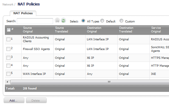
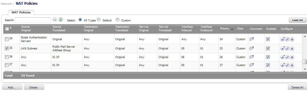
Go to the Network > NAT Policies page.
|
|
2
|
|
3
|
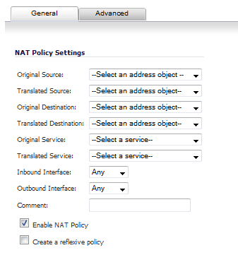
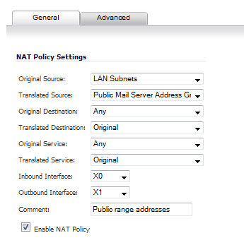
To create a NAT policy to allow all systems on the X2 interface to initiate traffic using the firewall’s WAN IP address, choose the following options:
|
|
4
|
Click on the Add button to add and activate the NAT Policy. The new policy is added to the NAT Policies table, and the status at the bottom of the browser window reads The configuration has been added.
|
|
5
|
|
NOTE: This policy can be duplicated for subnets behind the other interfaces of the firewall — just replace the Original Source with the subnet behind that interface, adjust the source interface, and add another NAT policy.
|
|
1
|
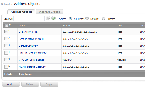
Go to the Network > Address Objects page.
|
|
2
|

|
3
|
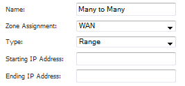
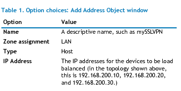
Enter a description for the range in the Name field.
|
|
4
|
|
5
|
|
6
|
Enter the range of addresses (usually public IP addresses supplied by your ISP) in the Starting IP Address and Ending IP Address fields,
|
|
7
|
Click on the Add button to create the range object. The new address object is added to the Address Objects table, and the status at the bottom of the browser screen reads The configuration has been added.
|
|
8
|
|
9
|
Navigate to the Network > NAT Policies page.
|
|
10
|
Click the Add button at the bottom of the Nat Policies table. The Add NAT Policy window is displayed.
|
|
12
|
Click on the Add button to add and activate the NAT Policy. The new policy is added to the NAT Policies table, and the status at the bottom of the browser window reads The configuration has been added.
|
|
13
|
Click on the Close button to close the Add NAT Policy window.
|
You can test the dynamic mapping by installing several systems on the LAN interface (by default, the X0 interface) at a spread-out range of addresses (for example, 192.168.10.10, 192.168.10.100, and 192.168.10.200) and accessing the public Website http://www.whatismyip.com from each system. Each system should display a different IP address from the range we created and attached to the NAT policy.
|
1
|
Go to Network > Address Objects.
|
|
2
|
|
4
|
Select the zone that the server assigned from the Zone Assignment menu.
|
|
5
|
|
6
|
Enter the server’s private IP address in the IP Address field.
|
|
7
|
Click Add. The new address object is added to the Address Objects table, and the status at the bottom of the browser screen reads The configuration has been added.
|
|
8
|
Then, create another object in the Add Address Object window for the server’s public IP address and with the correct values, and select WAN from Zone Assignment menu.
|
|
9
|
Click on the Add button to create the address object. The new address object is added to the Address Objects table, and the status at the bottom of the browser screen reads The configuration has been added.
|
|
10
|
|
11
|
Navigate to the Network > NAT Policies page.
|
|
12
|
Click the Add button at the bottom of the Nat Policies table. The Add NAT Policy window is displayed.
|
|
14
|
When done, click on the Add button to add and activate the NAT Policy.
|
|
15
|
Click on the Close button to close the Add NAT Policy window.
|
You can test the One-to-One mapping by opening up a Web browser on the server and accessing the public Website http://www.whatismyip.com. The Website should display the public IP address you attached to the private IP address in the NAT policy you just created.
This is the mirror policy for the one created in the previous section when you check Create a reflective policy. It allows you to translate an external public IP addresses into an internal private IP address. This NAT policy, when paired with a “permit” access policy, allows any source to connect to the internal server using the public IP address; the firewall handles the translation between the private and public address. With this policy in place, the firewall translates the server’s public IP address to the private IP address when connection requests arrive via the WAN interface (by default, the X1 interface).
|
1
|
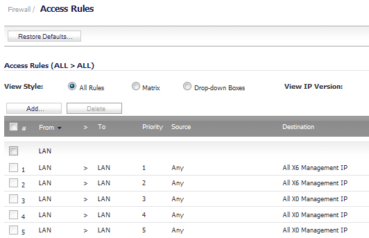
Go to the Firewall > Access Rules page.
|
|
3
|
|
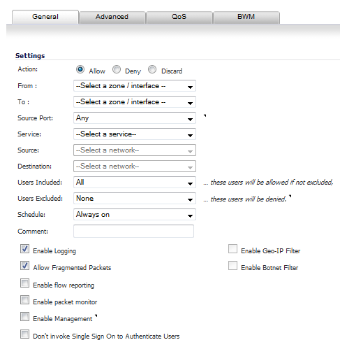
NOTE: If Source Port is configured, the Access Rule will filter the traffic based on the source port defined in the selected Service Object/Group. The Service Object/Group selected must have the same protocol types as the ones selected in Service
|
|
|
5
|
Click Add. The rule is added.
|
|
6
|
|
1
|
Go to the Firewall > Access Rules page.
|
|
2
|
|
3
|
|
NOTE: If Source Port is configured, the Access Rule will filter the traffic based on the source port defined in the selected Service Object/Group. The Service Object/Group selected must have the same protocol types as the ones selected in Service.
|
|
|
5
|
Click Add. The rule is added.
|
|
6
|
Next, create the following NAT policy by going to the Network > NAT Policies page.
|
7
|
Click the Add button at the bottom of the Nat Policies table. The Add NAT Policy window is displayed.
|
 |
|
|
9
|
When done, click on the Add button to add and activate the NAT Policy.
|
|
10
|
Click on the Close button to close the Add NAT Policy window.
|
|
a
|
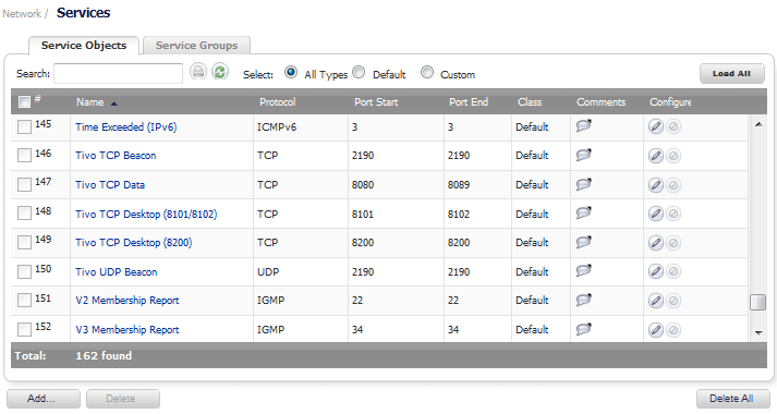
Go to the Network > Services page.
|
|
b
|
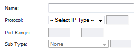
On the Service Objects tab, click the Add… button at the bottom of the tab. The Add Service window displays.
|
|
c
|
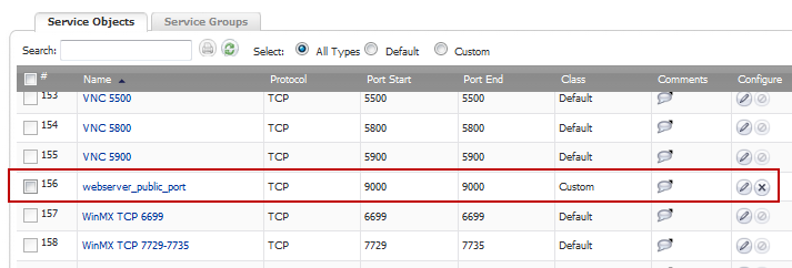
Give your custom service a friendly name such as webserver_public_port.
|
|
d
|
|
e
|
For the Port Range fields, enter in 9000 as the starting port number for the service and as its ending port number.
|
|
f
|
When done, click on the Add button to save the custom service. The message Done adding Service object entry displays and the Service Objects tab is updated.
|
|
g
|
|
a
|
Go to the Network > NAT Policies menu.
|
|
b
|
Click on the Edit button next to this NAT policy. The Edit NAT Policy window is displayed for editing the policy.
|
|
NOTE: Make sure you chose Any as the destination interface, and not the interface that the server is on. This may seem counter-intuitive, but it is actually the correct thing to do (if you try to specify the interface, you get an error).
|
|
d
|
When finished, click on the OK button to add and activate the NAT Policy.
|
|
a
|
Navigate to the Firewall > Access Rules page.
|
|
c
|
|
e
|
Click OK.
|
|
1
|
Go to the Firewall > Services page
|
|
2
|
|
3
|
|
4
|
Select TCP(6) as the protocol.
|
|
5
|
|
6
|
After configuring each custom service, click the Add button to save the custom services.
|
|
7
|
After configuring both custom services, click the Close button.
|
|
2
|
|
1
|
|
2
|
Enter a descriptive name for server’s private IP addresses, such as public_ports, in the Name field.
|
|
3
|
Select the zone that the servers are in from the Zone Assignment drop-down menu.
|
|
4
|
|
5
|
Enter the server’s private IP addresses in the IP Address field.
|
|
6
|
After configuring the address object, click the Add button to create the address object.
|
|
7
|
Click the Close button to close the window.
|
|
3
|
Go to the Network > NAT Policies page.
|
|
1
|
|
3
|
After configuring the NAT policy for each server, click the Add button to add and activate that NAT policy.
|
|
4
|
|
4
|
Click the Add button on the Network > NAT Policies page again. The Add NAT Policy window is displayed.
|
|
NOTE: Make sure you choose Any as the destination interface, and not the interface that the server is on. This may seem counter-intuitive, but it is actually the correct thing to do (if you try to specify the interface, you get an error).
|
||
|
2
|
After configuring the NAT policy for each server, click the Add button to add and activate that NAT policy.
|
|
3
|
|
1
|
Go to the Firewall > Access Rules page
|
|
3
|
|
5
|
After configuring the Access Rule for each server, click the Add button to add and activate that Access Rule.
|
|
6
|