You can access the packet monitor tool on the Dashboard > Packet Monitor page of the SonicOS management interface. There are six main areas of configuration for packet monitor, one of which is specifically for packet mirror. The following sections describe the configuration options, and provide procedures for accessing and configuring the filter settings, log settings, and mirror settings:
|
1
|
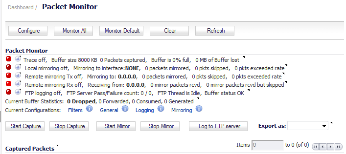
Navigate to the Dashboard > Packet Monitor page.
|
|
2
|
|
3
|
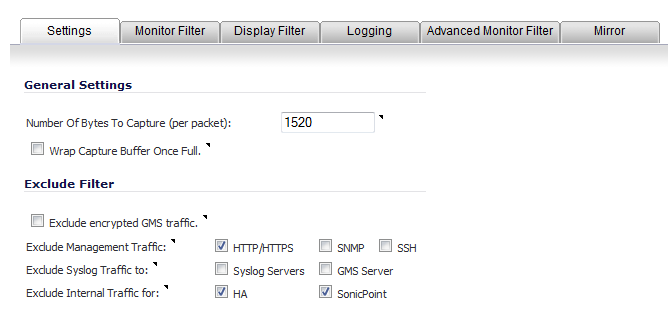
In the General Settings section, in the Number of Bytes To Capture (per packet) field, enter the number of bytes to capture from each packet. The minimum value is 64, the default value is 1520. You can enter this number as a hexadecimal figure.
|
|
4
|
To continue capturing packets after the buffer fills up, select the Wrap Capture Buffer Once Full checkbox. Selecting this option causes packet capture to start writing captured packets at the beginning of the buffer again after the buffer fills. This option has no effect if FTP server logging is enabled on the Logging tab because the buffer is automatically wrapped when FTP is enabled.
|
|
5
|
In the Exclude Filter section, select the Exclude encrypted GMS traffic to prevent capturing or mirroring of encrypted management or syslog traffic to or from SonicWALL GMS. This setting only affects encrypted traffic within a configured primary or secondary GMS tunnel. GMS management traffic is not excluded if it is sent via a separate tunnel.
|
|
6
|
Use the Exclude Management Traffic settings to prevent capturing or mirroring of management traffic to the appliance. Select the checkbox for each type of traffic to exclude:
|
|
•
|
HTTP/HTTPS (selected by default)
|
|
•
|
|
•
|
|
7
|
Use the Exclude Syslog Traffic to settings to prevent capturing or mirroring of syslog traffic to the logging servers. Select the checkbox for each type of server to exclude:
|
|
9
|
Use the Exclude Internal Traffic for settings to prevent capturing or mirroring of internal traffic between the firewall and its High Availability partner or a connected SonicPoint. Select the checkbox for each type of traffic to exclude:
|
|
•
|
HA (selected by default)
|
|
10
|
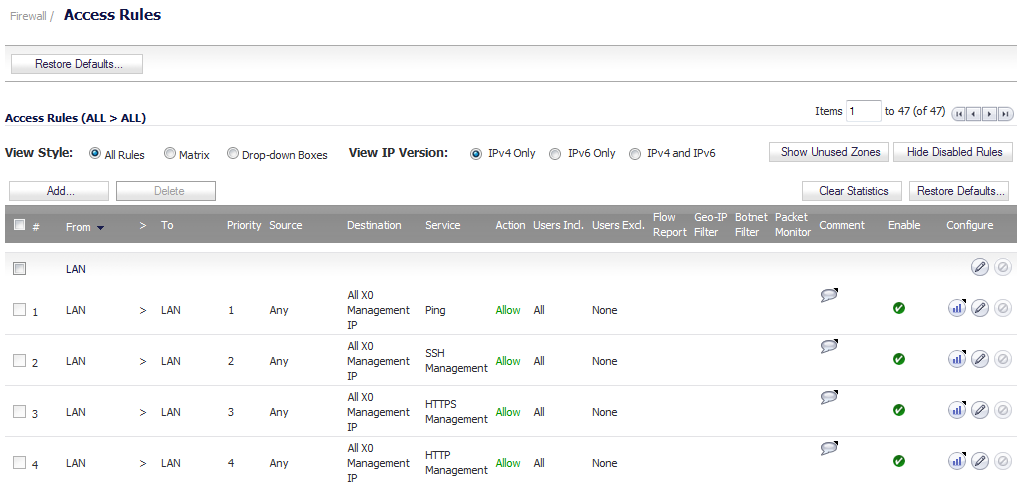
The Packet Monitor and Flow Reporting features allow traffic to be monitored based on firewall rules for specific inbound or outbound traffic flows. This feature set is enabled by choosing to monitor flows in the Firewall > Access Rules area of the SonicOS management interface.
|
1
|
Navigate to the Firewall > Access Rules page
|
|
2
|
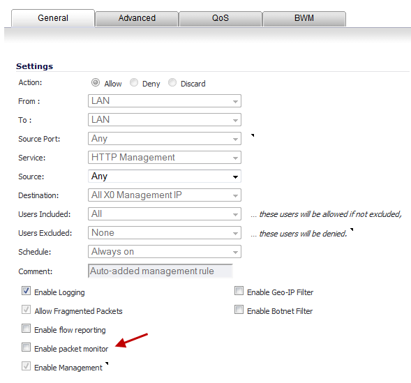
Click the Configure icon for the rule(s) on which to enable packet monitoring or flow reporting. The Edit Rule dialog displays.
|
|
3
|
Select the Enable packet monitor checkbox to send packet monitoring statistics for this rule.
|
|
4
|
Click the OK button to save your changes.
|
|
NOTE: Further monitor filter settings are required on the Dashboard > Packet Monitor page to enable monitoring based on firewall rules.
|
|
1
|
Navigate to the Dashboard > Packet Monitor page.
|
|
2
|
|
3
|
Click the Monitor Filter tab.
|
|
4
|
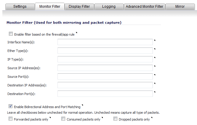
if you are using firewall rules to capture specific traffic, select Enable filter based on the firewall rule.
|
|
NOTE: Before selecting this option, be certain you have selected one or more access rules on which to monitor packet traffic. This configuration is done from the Firewall > Access Rules page; for more information about configuring access rules, see Configuring Firewall Access Rules .
|
|
•
|
Interface Name(s) - Specify the name(s) of the interface(s) on which to perform packet capture. You can specify up to ten interfaces separated by commas. The specified interface names should be the same as those listed in the Network > Interface page; for example:
|
|
•
|
Ether Type(s) - Specify the name of the Ethernet type(s) on which to perform filtering of the captured packets. You can specify up to ten Ethernet types separated by commas. This option is not case-sensitive. Currently, the following Ethernet types are supported: ARP (arp), IP (ip), PPPoE-SES, and PPPoE-DIS. The latter two can be specified by PPPoE alone.
|
You can also use hexadecimal values to represent the Ethernet types, or mix hex values with the standard representations; for example: ARP, 0x800, ip. Normally you would only use hex values for Ethernet types that are not supported by acronym in SonicOS. See Supported Packet Types .
|
•
|
IP Type(s) - Specify the name(s) of the IP packet type(s) on which to perform packet capture. You can specify up to ten IP types separated by commas. This option is not case-sensitive. The following IP types are supported: TCP, UDP, ICMP, GRE, IGMP, AH, ESP.
|
You can also use hexadecimal values to represent the IP types, or mix hex values with the standard representations; for example: TCP, 0x1, 0x6. See Supported Packet Types .
|
•
|
Source IP Address(es) - Specify the source IP address(es) on which to perform packet capture.
|
|
•
|
Source Port(s) - Specify the source port(s) on which to perform packet capture.
|
|
•
|
Destination IP Address(es) - Specify the destination IP address(es) on which to perform packet capture.
|
|
•
|
Destination Port(s) - Specify the destination port address(es) on which to perform packet capture.
|
|
•
|
Enable Bidirectional Address and Port Matching - Select this option to match IP addresses and/or ports specified in the above source and/or destination fields against both the source and/or destination fields in each packet. This option is selected by default.
|
|
•
|
Forwarded packets only - Select this option to monitor any packets forwarded by the firewall.
|
|
•
|
Consumed packets only - Select this option to monitor all packets consumed by internal sources within the firewall.
|
|
•
|
Dropped packets only - Select this option to monitor all packets dropped at the perimeter.
|
|
1
|
Navigate to the Dashboard > Packet Monitor page.
|
|
2
|
|
3
|
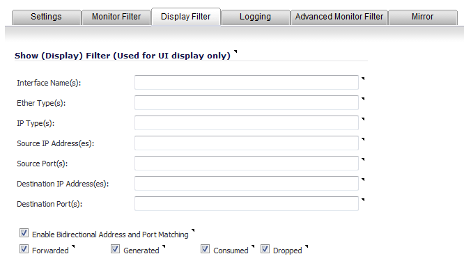
Click the Display Filter tab.
|
|
•
|
Interface Name(s) - Specify the name(s) of the interface(s) on which to perform packet capture. You can specify up to ten interfaces separated by commas. The specified interface names should be the same as those listed in the Network > Interface page; for example:
|
|
•
|
Ether Type(s) - Specify the name of the Ethernet type(s) on which to perform filtering of the captured packets. You can specify up to ten Ethernet types separated by commas. This option is not case-sensitive. Currently, the following Ethernet types are supported: ARP (arp), IP (ip), PPPoE-SES, and PPPoE-DIS. The latter two can be specified by PPPoE alone.
|
You can also use hexadecimal values to represent the Ethernet types, or mix hex values with the standard representations; for example: ARP, 0x800, ip. Normally you would only use hex values for Ethernet types that are not supported by acronym in SonicOS. See Supported Packet Types .
|
•
|
IP Type(s) - Specify the name(s) of the IP packet type(s) on which to perform packet capture. You can specify up to ten IP types separated by commas. This option is not case-sensitive. The following IP types are supported: TCP, UDP, ICMP, GRE, IGMP, AH, ESP.
|
You can also use hexadecimal values to represent the IP types, or mix hex values with the standard representations; for example: TCP, 0x1, 0x6. See Supported Packet Types .
|
•
|
Source IP Address(es) - Specify the source IP address(es) on which to perform packet capture.
|
|
•
|
Source Port(s) - Specify the source port(s) on which to perform packet capture.
|
|
•
|
Destination IP Address(es) - Specify the destination IP address(es) on which to perform packet capture.
|
|
•
|
Destination Port(s) - Specify the destination port address(es) on which to perform packet capture.
|
|
•
|
Enable Bidirectional Address and Port Matching - Select this option to match IP addresses and/or ports specified in the above source and/or destination fields against both the source and/or destination fields in each packet. This option is selected by default.
|
|
•
|
Forwarded - To display captured packets that the firewall has forwarded, select this checkbox.
|
|
•
|
Generated - To display captured packets that the firewall has generated, select this checkbox.
|
|
•
|
Consumed - To display captured packets that the firewall has consumed, select this checkbox.
|
|
•
|
Dropped - To display captured packets that the firewall has dropped, select this checkbox.
|
|
1
|
Navigate to the Dashboard > Packet Monitor page.
|
|
2
|
|
3
|
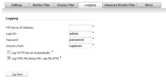
Click the Logging tab.
|
|
4
|
In the FTP Server IP Address field, enter the IP address of the FTP server where captured packets are to be logged.
|
|
5
|
In the Login ID field, enter the login name that the firewall should use to connect to the FTP server. The default value is admin.
|
|
6
|
In the Password field, enter the password that the firewall should use to connect to the FTP server. The default value is password.
|
|
7
|
In the Directory Path field, enter the directory path for the logged files. The captured files are written to this directory location at the FTP server relative to the default FTP root directory. The default value is captures.
|
|
•
|
libcap format, files are named packet-log--<>.cap, where the <> contains a run number and date including hour, month, day, and year. For example, packet-log--3-22-08292006.cap.
|
|
•
|
HTML format, file are named packet-log_h-<>.html, where the <> contains a run number and date including hour, month, day, and year. For example: packet-log_h-3-22-08292006.html.
|
|
8
|
To enable automatic logging of the capture file to a remote FTP server, select the Log To FTP Server Automatically checkbox. Captured files are named (where the <> contains a run number and date including hour, month, day, and year):
|
|
•
|
packet-log-<>.cap for libcap format; for example packet-log_3-22-08292006.cap.
|
|
•
|
packet-log-<>.html for HTML format; for example packet-log_3-22-08292006.html.
|
|
9
|
To enable transfer of the file in HTML format as well as libcap format, select the Log HTML File Along With .cap File (FTP). This option is selected by default.
|
|
10
|
To test the connection to the FTP server and transfer the capture buffer contents to it, click the Log Now. In this case, the file name will contain an F. For example, packet-log-F-3-22-08292006.cap or packet-log_h-F-3-22-08292006.html.
|
If automatic FTP logging is off, either because of a failed connection or simply disabled, you can restart it in Configure > Logging.
|
1
|
Navigate to the Dashboard > Packet Monitor page.
|
|
2
|
|
3
|
click the Logging tab.
|
|
4
|
|
5
|
To change the FTP logging status on the Dashboard > Packet Monitor page to active, select the Log To FTP Server Automatically checkbox.
|
|
6
|
Optionally, test the connection by clicking the Log Now button.
|
|
1
|
Navigate to the Dashboard > Packet Monitor page.
|
|
2
|
|
3
|
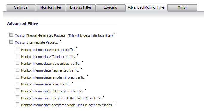
Click the Advanced Monitor Filter tab.
|
|
4
|
To capture packets generated by the firewall, select the Monitor Firewall Generated Packets (This will bypass interface filter) checkbox. This option is not selected by default.
|
Even when other monitor filters do not match, this option ensures that packets generated by the firewall are captured. This includes packets generated by such protocols as HTTP(S), L2TP, DHCP servers, PPP, PPPOE, and routing. Captured packets are marked with s in the incoming interface area when they are from the system stack. Otherwise, the incoming interface is not specified.
|
5
|
To capture intermediate packets generated by the firewall as a result of various policies, select the Monitor Intermediate Packets checkbox. Included are such packets as intermediate encrypted packets, IP help-generated packets, multicast packets that are replicated, and those generated as a result of fragmentation or reassembly.
|
|
•
|
Monitor intermediate multicast traffic – For multicast traffic.
|
|
•
|
Monitor intermediate IP helper traffic – For replicated IP Helper packets.
|
|
•
|
Monitor intermediate reassembled traffic – For reassembled IP packets.
|
|
•
|
Monitor intermediate fragmented traffic – For packets fragmented by the firewall.
|
|
•
|
Monitor intermediate remote mirrored traffic – For remote mirrored packets after de-encapsulation.
|
|
•
|
Monitor intermediate IPsec traffic – For IPSec packets after encryption and decryption.
|
|
•
|
Monitor intermediate SSL decrypted traffic – For SSL decrypted packets.
|
|
•
|
Monitor intermediate decrypted LDAP over TLS packets – For decrypted LDAP over TLS (LDAPS) packets. The packets are marked with ldp in the ingress/egress interface fields and have dummy Ethernet, IP, and TCP headers with some inaccurate fields. The LDAP server port is set to 389 so an external capture analysis program decode it as LDAP. Passwords in captured LDAP bind requests are obfuscated.
|
|
•
|
Monitor intermediate decrypted Single Sign On agent messages – For decrypted messages to or from the SSO authentication agent. The packets are marked with sso in the ingress/egress interface fields and have dummy Ethernet, IP, and TCP headers with some inaccurate fields.
|
|
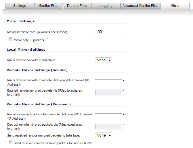
1
|
Navigate to the Dashboard > Packet Monitor page.
|
|
2
|
|
3
|
Click the Mirror tab.
|
|
4
|
Under Mirror Settings, enter the desired maximum rate for mirror data into the Maximum mirror rate (in kilobits per second) field. If this rate is exceeded during mirroring, the excess packets are not mirrored but counted as skipped packets. This rate applies to mirroring both locally to an interface or to a remote firewall. The default and minimum value is 100 kbps, and the maximum is 1 Gbps.
|
|
5
|
Select the Mirror only IP packets checkbox to prevent mirroring of any non-IP packets, such as ARP or PPPoE. If selected, this option overrides any non-IP Ether types entered in the Ether Type(s) field on the Monitor Filter tab.
|
|
6
|
Under Local Mirror Settings, select the destination interface for locally mirrored packets in the Mirror filtered packets to Interface drop-down menu. The default is None.
|
|
7
|
Under Remote Mirror Settings (Sender), in the Mirror filtered packets to remote Sonicwall firewall (IP Address) field, enter the IP address of the remote SonicWALL where mirrored packets are sent. Packets are encapsulated and set to the remote device (specified IP address).
|
|
8
|
In the Encrypt remote mirrored packets via IPSec (preshared key-IKE) field, enter the c pre-shared key to be used to encrypt traffic when sending mirrored packets to the remote firewall. Configuring this field enables an IPSec transport mode tunnel between this appliance and the remote firewall. This pre-shared key is used by IKE to negotiate the IPSec keys.
|
|
9
|
Under Remote Mirror Settings (Receiver), in the Receive mirrored packets from remote Sonicwall firewall (IP Address) field, enter the IP address of the remote appliance that receives mirrored packets. Packets are decapsulated and sent either to a local buffer or out of another interface as specified in the following options.
|
|
10
|
In the Decrypt remote mirrored packets via IPSec (preshared key-IKE) field, enter the previously configured pre-shared key to be used to encrypt/decrypt traffic when receiving mirrored packets from the remote firewall. This pre-shared key is used by IKE to negotiate the IPSec keys.
|
|
11
|
To mirror received packets to another interface on the local SonicWALL, select the interface from the Send received remote mirrored packets to Interface drop-down menu. The default is None.
|
|
12
|
To save all remote mirrored packets in the local capture buffer, select the Send received remote mirrored packets to capture buffer checkbox. This option is independent of sending mirrored packets to another interface, and both can be enabled if desired.
|