High Availability : High Availability

Active/Active Clustering Full-Mesh
This section contains the following subsections:
Active/Active Clustering Full-Mesh Overview
Active/Active Clustering Full-Mesh configuration is an enhancement to the Active/Active Clustering configuration option and prevents any single point of failure in the network. All firewall and other network devices are partnered for complete redundancy. Full-Mesh ensures that there is no single point of failure in your deployment, whether it is a device (firewall/switch/router) or a link. Every device is wired twice to the connected devices. Active/Active Clustering with Full-Mesh provides the highest level of availability possible with high performance.
About Full Mesh Deployments
Active/Active Clustering Full Mesh configuration is an enhancement to the Active/Active Clustering configuration option and provides the highest level of availability possible with high performance. Full Mesh deployments provide a very high level of availability for the network, because all devices have one or more redundant partners, including routers, switches, and security appliances. Every device is wired twice to the connected devices, so that no single point of failure exists in the entire network. For example, every SonicWALL firewall uses redundant ports to connect twice to each networking device.
Benefits of Active/Active Clustering Full Mesh
The following are key benefits to this deployment configuration:
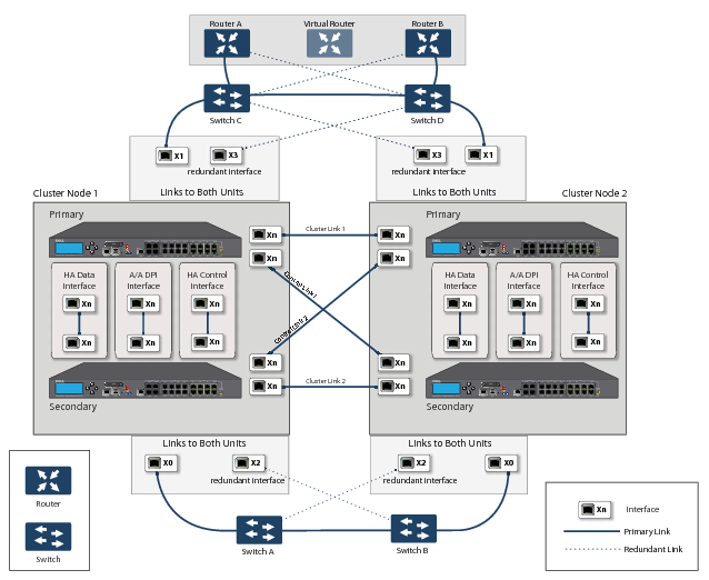
No Single Point of Failure in the Core Network: In an Active/Active Clustering Full-Mesh deployment, there is no single point of failure in the entire core network, not just for the firewalls. An alternative path for a traffic flow is always available in case there are simultaneous failures of switch, router, firewall on a path, thus providing the highest levels of availability.
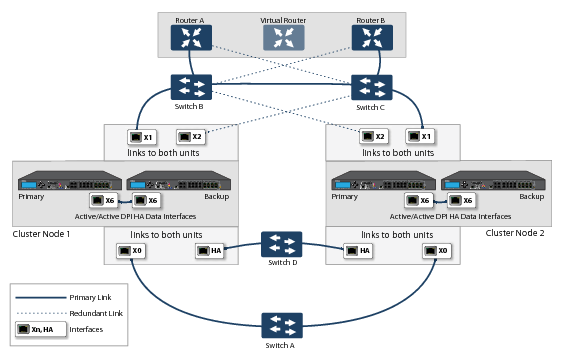
Port Redundancy: Active/Active Clustering Full-Mesh utilizes port redundancy in addition to HA redundancy within each Cluster Node, and node level redundancy within the cluster. With port redundancy, a backup link will take over in a transparent manner if the primary port fails. This prevents the need for device level failover.
Redundant Ports and Redundant Switches
Redundant ports can be used along with Active/Active Clustering. If one port should have a fault, the traffic is seamlessly handled through the redundant port without causing an HA or Active/Active failover. A Redundant Port field in the Network > Interfaces > Edit Interface page becomes available when Active/Active Clustering is enabled.
When configuring a redundant port, the interface must be unused; that is, not assigned to any zone. The two ports must be physically connected to the same switch, or preferably, to redundant switches in the network.
While all Cluster Nodes are up and processing traffic normally, redundant ports remain standby and are ready for use if the partner port goes down for any reason. If one Cluster Node goes down, causing an Active/Active failover, the redundant port on the remaining Cluster Node is put to use immediately to handle the traffic for the Virtual Group that was owned by the failed node. This provides load sharing.
For example, say we have a deployment in which Virtual Group 1 is owned by Cluster Node 1 and Virtual Group 2 is owned by Cluster Node 2. The Cluster Nodes are configured with redundant ports, X3 and X4. No traffic is sent on X4 while all nodes are functioning properly. If Cluster Node 2 goes down, Virtual Group 2 is now also owned by Cluster Node 1. At this point, the redundant port X4 begins to be used for load sharing. Virtual Group 1 traffic is sent on X3, while Virtual Group 2 traffic is sent on X4. In a larger deployment, if Cluster Node 1 owns three or four Virtual Groups, traffic is distributed among the redundant ports – traffic for Virtual Groups 1 & 3 is sent on X3, while traffic for Virtual Groups 2 & 4 is sent on X4.
When a redundant switch is configured, SonicWALL recommends using a redundant port to connect to it. While it is possible to connect a redundant switch without using a redundant port, this involves complex configuration using probes. A redundant switch can be deployed anywhere in the network depending on the need for high availability. For example, a redundant switch might be deployed on the WAN side if traffic passing through it is business-critical.
This diagram shows a deployment that includes redundant routers, switches, and ports on the WAN side, but is not a Full Mesh deployment because the LAN side does not use redundancy.
Figure 38. WAN side redundancy
Full Mesh is not required when deploying redundant ports or switches, but a Full Mesh deployment includes them. A Full Mesh deployment uses redundant ports on each of the main traffic ports (LAN, WAN, etc.), and uses redundant upstream routers in addition to redundant switches.
For more information about Full Mesh deployments, see the Active/Active Clustering Full Mesh Deployment Technote.
Configuring Active/Active Clustering Full Mesh
This section describes the procedure for setting up an Active/Active Cluster Full-Mesh deployment. It describes a 4 unit Active/Active Clustering Full-Mesh setup. We will go over the following aspects of the deployment:
The deployments described are examples. Your actual deployment might differ based on the following factors:
Figure 39. Active/Active four-unit cluster full mesh
Cabling for Active/Active Full Mesh
This procedure describes the cabling for the deployment illustrated in the above diagram.
To physically connect your network devices for a full-mesh deployment, perform the following steps:
1
2
a
b
c
d
3
a
b
4
a
b
c
d
5
a
b
6
7
8
9
10
a
b
c
d
Configuring Active/Active Cluster Firewalls
This section describes the steps to configure the Active/Active Cluster firewalls.
1
2
On the High Availability > Settings page:
a
b
c
d
e
f
g
Click Submit.
3
On the Network > Interfaces page:
a
b
4
On the High Availability > Monitoring page, add the monitoring/management IP addresses either on X0 or X1 for each unit in the cluster.
5
6
a
b
Testing for No Point of Failure
After the above deployment is connected and configured, CN1 will own Virtual Group1 (VG1), and CN2 will own Virtual Group 2 (VG2).
Configure the VG1 IP address on X0 as the gateway for a certain set of traffic flows and the VG2 IP address on X0 as the gateway for other sets of traffic flows. The network administrator can use different methods to accomplish this. One way is to use a smart DHCP server which distributes the gateway allocation to the PCs on the directly connected client network. Another method is by using policy based routes on a downstream router.
When the traffic setup is done, both Cluster Nodes will actively process network traffic. Now we can test for no single point of failure on all devices and links with the following steps:
1
Device Failures: Traffic should continue to flow through both Cluster Nodes in each of the following device failures:
a
b
c
d
e
Repeat Step c and Step d for CN2.
f
g
2
Link Failures: Traffic should continue to flow in each of the following link failures:
a
b
c
d
Configuring Active/Active Cluster Full-Mesh 2-Unit Deployment
In previous sections we discussed the Active/Active Cluster Full-Mesh with 4 firewall units. Optionally, you can deploy Active/Active Cluster Full-Mesh with 2 firewall units where each CN consists of only one firewall (no HA backup). However, such a setup has the following limitations:
The procedure for the 2-unit Full-Mesh is similar to the procedure for the 4-unit Full-Mesh, with the following exceptions: