|
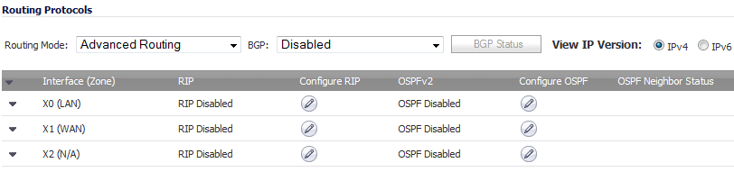
By default, Advanced Routing Services are disabled, and must be enabled to be made available. At the top of the Network > Routing page, is a drop-down menu for Routing mode. When you select Use Advanced Routing, the top of the Network > Routing page will look as follows:
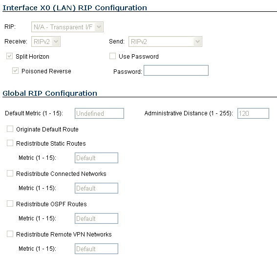
To configure RIP routing on an interface, select the Configure icon in the interface’s row under the Configure RIP column. This will launch the RIP Configuration window.
|
•
|
RIP – Select one of these modes from the drop-down menu:
|
|
•
|
Disabled – RIP is disabled on this interface
|
|
•
|
Send and Receive – The RIP router on this interface will send updates and process received updates.
|
|
•
|
Send Only – The RIP router on this interface will only send updates, and will not process received updates. This is similar to the basic routing implementation.
|
|
•
|
Receive Only – The RIP router on this interface will only process received updates.
|
|
•
|
Passive – The RIP router on this interface will not process received updates, and will only send updates to neighboring RIP routers specified with the CLI neighbor command. This mode should be used only when configuring advanced RIP options from the ars-rip CLI.
|
|
•
|
Receive (available in Send and Receive and Receive Only modes)
|
|
•
|
RIPv1 – Receive only broadcast RIPv1 packets.
|
|
•
|
RIPv2 – Receive only multicast RIPv2 packets. RIPv2 packets are sent by multicast, although some implementations of RIP routers (including basic routing on SonicWALL devices) have the ability to send RIPv2 in either broadcast or multicast formats.
|
|
•
|
Send (available in Send and Receive and Send Only modes)
|
|
•
|
|
•
|
RIPv2 - v1 compatible – Send multicast RIPv2 packets that are compatible with RIPv1.
|
|
•
|
|
•
|
Split Horizon – Enabling Split Horizon will suppress the inclusion of routes sent in updates to routers from which they were learned. This is a common RIP mechanism for preventing routing loops. See Maximum Hops .
|
|
•
|
Poisoned Reverse – Poison reverse is an optional mode of Split Horizon operation. Rather than suppressing the inclusion of learned routes, the routes are sent with a metric of infinity (16) thus indicating that they are unreachable. See Maximum Hops .
|
|
•
|
Use Password – Enables the use of a plain-text password on this interface, up to 16 alpha-numeric characters long, for identification.
|
|
•
|
Default Metric – Used to specify the metric that will be used when redistributing routes from other (Default, Static, Connected, OSPF, or VPN) routing information sources. The default value (undefined) is 1 and the maximum is 15.
|
|
•
|
Administrative Distance – The administrative distance value is used by routers in selecting a path when there is more than one route to a destination, with the smaller distance being preferred. The default value is 120, minimum is 1, and maximum is 255.
|
|
•
|
Originate Default Route – This checkbox enables or disables the advertising of the firewall’s default route into the RIP system.
|
|
•
|
Redistribute Static Routes – Enables or disables the advertising of static (Policy Based Routing) routes into the RIP system. The metric can be explicitly set for this redistribution, or it can use the value (default) specified in the Default Metric setting.
|
|
•
|
Redistribute Connected Networks - Enables or disables the advertising of locally connected networks into the RIP system. The metric can be explicitly set for this redistribution, or it can use the value (default) specified in the Default Metric setting.
|
|
•
|
Redistribute OSPF Routes - Enables or disables the advertising of routes learned via OSPF into the RIP system. The metric can be explicitly set for this redistribution, or it can use the value (default) specified in the Default Metric setting.
|
|
•
|
Redistribute Remote VPN Networks - Enables or disables the advertising of static (Policy Based Routing) routes into the RIP system. The metric can be explicitly set for this redistribution, or it can use the value (default) specified in the Default Metric setting.
|
Routes learned via RIP will appear in the Route Policies table as OSPF or RIP route.
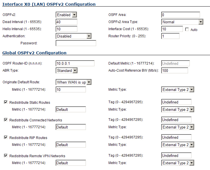
To configure OSPF routing on the X0 and the X4:100 interfaces, select the Configure icon in the interface’s row under the Configure OSPF column. This will launch the following window:
|
•
|
OSPFv2 – Select one of these settings from the drop-down menu:
|
|
•
|
Disabled – OSPF Router is disabled on this interface
|
|
•
|
Enabled – OSPF Router is enabled on this interface
|
|
•
|
Passive – The OSPF router is enabled on this interface, but only advertises connected networks using type 1 LSA’s (Router Link Advertisements) into the local area. This is different from the Redistribute Connected Networks options, which would cause the OSPF router to behave as an ASBR, and to use type 5 LSA’s (AS External Link Advertisement) to flood the advertisements into all non-stub areas. For more information, see OSPF Terms .
|
|
•
|
Dead Interval – The period after with an entry in the LSDB is removed if not Hello is received. The default is 40 seconds, with a minimum of 1 and a maximum on 65,535. Be sure this value agrees with the other OSPF routers on the segment for successful neighbor establishment.
|
|
•
|
Hello Interval – The period of time between Hello packets. The default is 10 seconds, with a minimum of 1 and a maximum on 65,535. Be sure this value agrees with the other OSPF routers on the segment for successful neighbor establishment.
|
|
•
|
Authentication - Be sure this setting agrees with the other OSPF routers on the segment for successful neighbor establishment.
|
|
•
|
Disabled – No authentication is used on this interface.
|
|
•
|
Simple Password – A plain-text password is used for identification purposes by the OSPF router on this interface.
|
|
•
|
Message Digest – An MD5 hash is used to securely identify the OSPF router on this interface.
|
|
•
|
OSPF Area – The OSPF Area can be represented in either IP or decimal notation. For example, you may represent the area connected to X4:100 as either 100.100.100.100 or 1684300900.
|
|
•
|
|
•
|
Normal – Receives and sends all applicable LSA types.
|
|
•
|
Stub Area – Does not receive type 5 LSA’s (AS External Link Advertisements).
|
|
•
|
Totally Stubby Area – Does not receive LSA types 3, 4, or 5.
|
|
•
|
Not So Stubby Area – Receives type 7 LSA’s (NSSA AS External Routes).
|
|
•
|
Totally Stubby NSSA – Receives type 1 and 2 LSA’s.
|
|
•
|
Interface Cost – Specifies the overhead of sending packets across this interface. The default value is 10, generally used to indicate an Ethernet interface. The minimum value is 1 (for example, Fast Ethernet) and the maximum value is 65,535 (for example, pudding).
|
|
•
|
Router Priority – The router priority value is used in determining the Designated Router (DR) for a segment. The higher the value, the higher the priority. In the event of a priority tie, the Router ID will act as the tie-breaker. Setting a value of 0 makes the OSPF router on this interface ineligible for DR status. The default value is 1, and the maximum value is 255.
|
|
•
|
OSPF Router ID – The Router ID can be any value, represented in IP address notation. It is unrelated to the any of the IP addresses on the firewall, and can be set to any unique value within your OSPF network.
|
|
•
|
ABR Type – Allows for the specification of the topology with which this OSPF router will be participating, for the sake of compatibility. The options are:
|
|
•
|
Standard – Full RFC2328 compliant ABR OSPF operation.
|
|
•
|
Cisco – For interoperating with Cisco’s ABR behavior, which expects the backbone to be configured and active before setting the ABR flag.
|
|
•
|
IBM – For interoperating with IBM’s ABR behavior, which expects the backbone to be configured before settings the ABR flag.
|
|
•
|
Shortcut – A shortcut area enables traffic to go through the non-backbone area with a lower metric whether or not the ABR router is attached to area 0.
|
|
•
|
Default Metric – Used to specify the metric that will be used when redistributing routes from other (Default, Static, Connected, RIP, or VPN) routing information sources. The default value (undefined) is 1 and the maximum is 16,777,214.
|
|
•
|
Originate Default Route – Controls the advertising of the firewall’s default route into the OSPF system on this interface. The options are:
|
|
•
|
Never – Disables advertisement of the default route into the OSPF system.
|
|
•
|
When WAN is up – Advertises the default route into the OSPF system when the WAN is online. The default route is always advertised as an External Type 2 using LSA Type 5.
|
|
•
|
Always – Enables advertisement of the default route into the OSPF system. The default route is always advertised as an External Type 2 using LSA Type 5.
|
|
•
|
Redistribute Static Routes – Enables or disables the advertising of static (Policy Based Routing) routes into the OSPF system.
|
|
NOTE: The following applies to all Redistributed routes: The metric can be explicitly set for this redistribution, or it can use the value (default) specified in the Default Metric setting. An optional route tag value can be added to help other routers identify this redistributed route (the default tag value is 0). The redistributed route advertisement will be an LSA Type 5, and the type may be selected as either Type 1 (adds the internal link cost) or Type 2 (only uses the external link cost).
|
|
•
|
Redistribute Connected Networks - Enables or disables the advertising of locally connected networks into the OSPF system.
|
|
•
|
Redistribute RIP Routes - Enables or disables the advertising of routes learned via RIP into the OSPF system.
|
|
•
|
Redistribute Remote VPN Networks - Enables or disables the advertising of static (Policy Based Routing) routes into the RIP system.
|
The Routing Protocols section will show the status of all active OSPF routers by interface.
VPN Tunnel Interfaces can be configured for advanced routing. To do so, you must enable advanced routing for the tunnel interface on the Advanced tab of its configuration. See Adding a Tunnel Interface for more information.
After you have enabled advanced routing for a Tunnel Interface, it is displayed in the list with the other interfaces in the Advanced Routing table on the Network > Routing page.
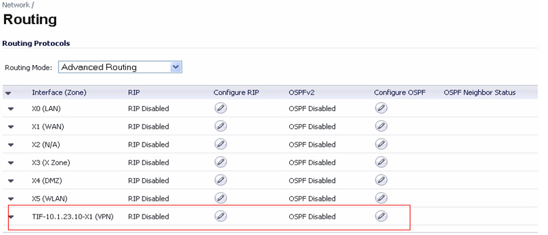
To configure Advanced Routing options, click on the Edit icon in the Configure RIP or Configure OSPF column for the Tunnel Interface you wish to configure.
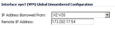
The RIP and OSPF configurations for Tunnel Interfaces are very similar to the configurations for traditional interfaces with the addition of two new options that are listed at the bottom of the RIP or OSPF configuration window under a new Global Unnumbered Configuration heading.
|
•
|
IP Address Borrowed From - The interface whose IP address is used as the source IP address for the Tunnel Interface.
|
|
•
|
Remote IP Address - The IP address of the remote peer to which the Tunnel Interface is connected. In the case of a SonicWALL-to-SonicWALL configuration with another Tunnel Interface, this should be the IP address of the borrowed interface of the Tunnel Interface on the remote peer.
|
|
NOTE: The IP Address Borrowed From and Remote IP Address values apply to both RIP and OSPF for the Tunnel Interface. Changing one of these values in RIP will change the value in OSPF and vice versa.
|