U0_interface
Configuring the U0/U1/M0 External 3G/4G/Modem Interface
The SonicWALL security appliances with a USB port support an external 3G/mobile or analog modem interface. Depending on your appliance, when an analog modem or 3G device is installed prior to starting the appliance, it will be listed as the U0, U1, or M0 (NSA 240 only) interface on the Network > Interfaces page.
The U0/U1/M0 interface must be initially configured on the on the 3G or Modem tab in the left-side navigation bar. Once you have a created configuration profile for the interface, the configuration can be modified from the Network > Interfaces page. For additional information on 3G or analog modem external interfaces, see 3G/4G/Modem.
Note The SonicWALL security appliance must be rebooted before it will recognize the external 3G/mobile or analog modem interface.
To manually initiate a connection on the U0/U1/M0 external 3G/modem interface, perform the following steps:
1. On the Network > Interfaces page, click on the Manage button for the U0/U1/M0 interface.
2. The U0/U1/M0 Connection Status window displays. Click the Connect button. Once the connection is active, the U0/U1/M0 Connection Status window displays statistics on the session.
For a detailed explanation of the behavior of the Ethernet with 3G Failover setting see Understanding 3G/4G Connection Types.
To configure the U0/U1/M0 interface from the Network > Interfaces page, perform the following steps.
1. Click the configure icon for the U0/U1/M0 interface.
If the interface will be used in Connect on Data mode, select the categories of traffic that will trigger the interface to automatically connect when the appliance detects those types of traffic. The following categories are supported:
• NTP packets
• GMS Heartbeats
• System log e-mails
• AV Profile Updates
• SNMP Traps
• Licensed Updates
• Firmware Update requests
• Syslog traffic
Note To configure the SonicWALL appliance for Connect on Data operation, you must select Connect on Data as the Connection Type for the Connection Profile. See 3G/4G > Connection Profiles for more details.
3. Select the appropriate Management/User Login options to enable remote management of the SonicWALL appliance over the 3G interface.
You can select any of the supported management protocol(s): HTTPS, Ping, SNMP, and/or SSH. You can also select HTTP for management traffic. However, bear in mind that HTTP traffic is less secure than HTTPS.
Note Remote manage the appliance over the U0/U1/M0 interface requires that the 3G provider (1) issues a publicly routable IP address upon connection to the 3G network and (2) allows external connection to be initiated on their network. Please contact your 3G provider to determine if they support these requirements.
4. Select Add rule to enable redirect from HTTP to HTTPS to have the SonicWALL automatically convert HTTP requests to HTTPS requests for added security.
5. To select the preferred configuration profiles for the interface, click the Profiles tab.
6. Select the appropriate connection profiles for Primary Profile, Alternate Profile 1, and Alternate Profile 2.
Note The connection profiles must be initially configured on the 3G > Connection Profiles page. See 3G/4G > Connection Profiles for more details.
7. Click on the Advanced tab.
Check the Enable Remotely Triggered Dial-Out checkbox to enable network administrators to remotely initiate a WAN modem connection. For more information, see Remotely Triggered Dial-Out.
9. (Optional) To authenticate the remote call, check the Requires authentication checkbox and enter the password in the Password and Confirm Password fields.
10. In the Max Hosts field, enter the maximum number of hosts to allow when this interface is connected. The default value is “0”, which allows an unlimited number of nodes.
11. Click the Enable Egress Bandwidth Management checkbox to enable bandwidth management policy enforcement on outbound traffic.
12. Click the Enable Ingress Bandwidth Management checkbox to enable bandwidth management policy enforcement on inbound traffic.
13. Select a Compression Multiplier from the drop-down list as necessary to appropriately adjust bandwidth calculations if the dial-up device performs compression.
14. Select the Enable flow reporting checkbox to have the data for flows on this interface reported to Flow Reporting and the Real-Time Monitor.
Note In earlier SonicOS releases, the failover behavior for the 3G/Modem interface was configured on the Network > Interfaces page. Beginning in SonicOS 5.8, 3G/Modem failover is configured on the Network > Failover & LB page. See Network > Failover & Load Balancing for more information.
Configuring SonicWALL PortShield Interfaces (TZ series, NSA 240, and NSA 2400MX)
PortShield architecture enables you to configure some or all of the LAN ports into separate security contexts, providing protection not only from the WAN and DMZ, but between devices inside your network as well. In effect, each context has its own wire-speed PortShield that enjoys the protection of a dedicated, deep packet inspection firewall.
PortShield is supported on SonicWALL TZ Series, NSA 240, and NSA 2400MX appliances.
Tip Zones can always be applied to multiple interfaces in the Network > Interfaces page, even without the use of PortShield groupings. However, these interfaces will not share the same network subnet unless they are grouped using PortShield.
You can assign any combination of ports into a PortShield interface. All ports you do not assign to a PortShield interface are assigned to the LAN interface.
To configure a PortShield interface, perform the following steps:
1. Click on the Network > Interfaces page.
Click the Configure button for the interface you want to configure. The Edit Interface window displays.
In the Zone pulldown menu, select on a zone type option to which you want to map the interface.
Note You can add PortShield interfaces only to Trusted, Public, and Wireless zones.
4. In the IP Assignment pulldown menu, select PortShield Switch Mode.
5. In the PortShield to pulldown menu, select the interface you want to map this port to. Only ports that match the zone you have selected are displayed.
Configuring VLAN Subinterfaces (SonicWALL NSA series appliances)
VLAN subinterfaces are supported on SonicWALL NSA series appliances. When you add a VLAN subinterface, you need to assign it to a zone, assign it a VLAN Tag, and assign it to a physical interface. Based on your zone assignment, you configure the VLAN subinterface the same way you configure a physical interface for the same zone.
Adding a virtual interface
1. Navigation to the Network > Interfaces page.
2. At the bottom of the Interface Settings table, click the Add Interface drop-down menu and select Virtual Interface.
The Edit Interface window displays.
Select a zone to assign to the interface. You can select LAN, WAN, DMZ, WLAN, or create a zone. The zone assignment does not have to be the same as the parent (physical) interface. In fact, the parent interface can even remain Unassigned.
Your configuration choices for the network settings of the subinterface depend on the zone you select.
• LAN, DMZ, or a custom zone of Trusted type: Static or Transparent. LAN can also select Tap Mode (1-Port Tap)
• WLAN or a custom Wireless zone: static IP only (no IP Assignment list).
4. Assign a VLAN tag (ID) to the subinterface. Valid VLAN ID’s are 1 to 4094, although some switches reserve VLAN 1 for native VLAN designation. You will need to create a VLAN subinterface with a corresponding VLAN ID for each VLAN you wish to secure with your security appliance.
5. Declare the parent (physical) interface to which this subinterface will belong. There is no per-interface limit to the number of subinterfaces you can assign – you may assign subinterfaces up to the system limit.
6. Configure the subinterface network settings based on the zone you selected. See the interface configuration instructions earlier in this chapter:
• Configuring the Static Interfaces
• Configuring Advanced Settings for the Interface
• Configuring Interfaces in Transparent Mode
• Configuring Wireless Interfaces
• Configuring the WLAN Interface (SonicWALL TZ series wireless appliances)
• Configuring SonicWALL PortShield Interfaces (TZ series, NSA 240, and NSA 2400MX)
• Configuring the U0/U1/M0 External 3G/4G/Modem Interface
• Configuring SonicWALL PortShield Interfaces (TZ series, NSA 240, and NSA 2400MX)
• Configuring VLAN Subinterfaces (SonicWALL NSA series appliances)
7. Select the management and user-login methods for the subinterface.
8. Click OK.
Configuring Layer 2 Bridge Mode
See the following sections:
• Configuration Task List for Layer 2 Bridge Mode
• Configuring Layer 2 Bridge Mode Procedure
• VLAN Integration with Layer 2 Bridge Mode (SonicWALL NSA series appliances)
• VPN Integration with Layer 2 Bridge Mode
Configuration Task List for Layer 2 Bridge Mode
• Choose a topology that suits your network
• Configuring the Common Settings for L2 Bridge Mode Deployments
– License UTM services
– Disable DHCP server
– Configure and enable SNMP and HTTP/HTTPS management
– Enable syslog
– Activate UTM services on affected zones
– Create firewall access rules
– Configure log settings
– Configure wireless zone settings
• Configuring the Primary Bridge Interface
– Select the zone for the Primary Bridge Interface
– Activate management
– Activate security services
• Configuring the Secondary Bridge Interface
– Select the zone for the Secondary Bridge Interface
– Activate management
– Activate security services
• Apply security services to the appropriate zones
Configuring the Common Settings for L2 Bridge Mode Deployments
The following settings need to be configured on your SonicWALL UTM appliance prior to using it in most of the Layer 2 Bridge Mode topologies.
When the appliance is successfully registered, go to the System > Licenses page and click Synchronize under Manage Security Services Online. This will contact the SonicWALL licensing server and ensure that the appliance is properly licensed.
To check licensing status, go to the System > Status page and view the license status of all the UTM services (Gateway Anti-Virus, Anti-Spyware, and Intrusion Prevention).
Disabling DHCP Server
When using a SonicWALL UTM appliance in Layer 2 Bridge Mode in a network configuration where another device is acting as the DHCP server, you must first disable its internal DHCP engine, which is configured and running by default. On the Network > DHCP Server page, clear the Enable DHCPv4 Server checkbox, and then click on the Accept button at the top of the screen.
Configuring SNMP Settings
On the System > SNMP page, make sure the checkbox next to Enable SNMP is checked, and then click on the Accept button at the top of the screen.
Then, click the Configure button. On the SNMP Settings page, enter all the relevant information for your UTM appliance: the GET and TRAP SNMP community names that the SNMP server expects, and the IP address of the SNMP server. Click OK to save and activate the changes.
Enabling SNMP and HTTPS on the Interfaces
On the Network > Interfaces page, enable SNMP and HTTP/HTTPS on the interface through which you will be managing the appliance.
Enabling Syslog
1. On the Log > Syslog page, click on the Add button.
The Add Syslog Server window displays:
2. Create an entry for the syslog server. Click OK to save and activate the change.
Activating UTM Services on Each Zone
On the Network > Zones page, for each zone you will be using, make sure that the UTM services are activated.
Then, on the Security Services page for each UTM service, activate and configure the settings that are most appropriate for your environment.
An example of the Gateway Anti-Virus settings is shown below:
An example of the Intrusion Prevention settings is shown below:
An example of the Anti-Spyware settings is shown below:
Creating Firewall Access Rules
If you plan to manage the appliance from a different zone, or if you will be using a server such as the HP PCM+/NIM server for management, SNMP, or syslog services, create access rules for traffic between the zones. On the Firewall > Access Rules page, click on the Configure icon for the intersection of the zone of the server and the zone that has users and servers (your environment may have more than one of these intersections). Create a new rule to allow the server to communicate with all devices in that zone.
Configuring Log Settings
On the Log > Categories page, set the Logging Level to Informational and the Alert Level to Critical. Click Accept to save and activate the change.
Then, go to the Log > Name Resolution page and set the Name Resolution Method to DNS then NetBios. Click Accept to save and activate the change.
Configuring Wireless Zone Settings
In the case where you are using a HP PCM+/NIM system, if it will be managing a HP ProCurve switch on an interface assigned to a WLAN/Wireless zone, you will need to deactivate two features, otherwise you will not be able to manage the switch. Go to the Network > Zones page and select your Wireless zone. On the Wireless tab, clear the checkboxes next to Only allow traffic generated by a SonicPoint and WiFiSec Enforcement. Click OK to save and activate the change.
Configuring Layer 2 Bridge Mode Procedure
Refer to L2 Bridge Interface Zone Selection, for choosing a topology that best suits your network. In this example, we will be using a topology that most closely resembles the Simple L2 Bridge Topology.
Choose an interface to act as the Primary Bridge Interface. Refer to L2 Bridge Interface Zone Selection, for information in making this selection. In this example, we will use X1 (automatically assigned to the Primary WAN):
Configuring the Primary Bridge Interface
1. Navigate to the Network > Interfaces page.
2. Click the Configure icon for the X1 (WAN) interface.
3. Configure the interface with a Static IP address (e.g. 10.203.15.82).
Note The Primary Bridge Interface must have a Static IP assignment.
4. Configure the default gateway. This is required for the security appliance itself to reach the Internet. (This applies only to WAN interfaces.)
5. Configure the DNS server. (This applies only to WAN interfaces.)
6. Configure management (HTTP, HTTPS, Ping, SNMP, SSH, User Logins, HTTP Redirects).
7. Click OK.
Choose an interface to act as the Secondary Bridge Interface. Refer to L2 Bridge Interface Zone Selection, for information in making this selection. In this example, we will use X0 (automatically assigned to the LAN):
Configuring the Secondary Bridge Interface
1. On the Network > Interfaces page, click the Configure icon in the right column of the X0 (LAN) interface.
2. In the IP Assignment drop-down list, select Layer 2 Bridged Mode.
3. In the Bridged to drop-down list, select the X1 interface.
4. Configure management (HTTP, HTTPS, Ping, SNMP, SSH, User Logins, HTTP Redirects).
5. You may optionally enable the Block all non-IPv4 traffic setting to prevent the L2 bridge from passing non-IPv4 traffic.
VLAN Filtering (SonicWALL NSA series appliances)
You may also optionally navigate to the VLAN Filtering tab to control VLAN traffic through the L2 bridge. By default, all VLANs are allowed:
• Select Block listed VLANs (blacklist) from the drop-down list and add the VLANs you wish to block from the left pane to the right pane. All VLANs added to the right pane will be blocked, and all VLANs remaining in the left pane will be allowed.
• Select Allow listed VLANs (whitelist) from the drop-down list and add the VLANs you wish to explicitly allow from the left pane to the right pane. All VLANs added to the right pane will be allowed, and all VLANs remaining in the left pane will be blocked.
6. Click OK.
The Network > Interfaces page displays the updated configuration:
You may now apply security services to the appropriate zones, as desired. In this example, they should be applied to the LAN, WAN, or both zones.
VLAN Integration with Layer 2 Bridge Mode (SonicWALL NSA series appliances)
VLANs are supported on SonicWALL NSA series appliances. When a packet with a VLAN tag arrives on a physical interface, the VLAN ID is evaluated to determine if it is supported. The VLAN tag is stripped, and packet processing continues as it would for any other traffic. A simplified view of the inbound and outbound packet path includes the following potentially reiterative steps:
1. IP validation and reassembly
2. Decapsulation (802.1q, PPP)
3. Decryption
4. Connection cache lookup and management
5. Route policy lookup
6. NAT Policy lookup
7. Access Rule (policy) lookup
8. Bandwidth management
9. NAT translation
10. Advanced Packet Handling (as applicable)
a. TCP validation
b. Management traffic handling
c. Content Filtering
d. Transformations and flow analysis (on SonicWALL NSA series appliances): H.323, SIP, RTSP, ILS/LDAP, FTP, Oracle, NetBIOS, Real Audio, TFTP
e. IPS and GAV
At this point, if the packet has been validated as acceptable traffic, it is forwarded to its destination. The packet egress path includes:
• Encryption
• Encapsulation
• IP fragmentation
On egress, if the route policy lookup determines that the gateway interface is a VLAN subinterface, the packet is tagged (encapsulated) with the appropriate VLAN ID header. The creation of VLAN subinterfaces automatically updates the SonicWALL’s routing policy table:
The auto-creation of NAT policies, Access Rules with regard to VLAN subinterfaces behave exactly the same as with physical interfaces. Customization of the rules and policies that govern the traffic between VLANs can be performed with customary SonicOS ease and efficiency.
When creating a zone (either as part of general administration, or as a step in creating a subinterface), a checkbox will be presented on the zone creation page to control the auto-creation of a GroupVPN for that zone. By default, only newly created Wireless type zones will have ‘Create GroupVPN for this zone’ enabled, although the option can be enabled for other zone types by selecting the checkbox during creation.
Management of security services between VLAN subinterfaces is accomplished at the zone level. All security services are configurable and applicable to zones comprising physical interfaces, VLAN subinterfaces, or combinations of physical and VLAN subinterfaces.
Gateway Anti-Virus and Intrusion Prevention Services between the different workgroups can easily be employed with the use of VLAN segmentation, obviating the need for dedicated physical interfaces for each protected segment.
VLAN support enables organizations to offer meaningful internal security (as opposed to simple packet filtering) between various workgroups, and between workgroups and server farms without having to use dedicated physical interfaces on the SonicWALL.
Here the ability to assign VLAN subinterfaces to the WAN zone, and to use the WAN client mode (only Static addressing is supported on VLAN subinterfaces assigned to the WAN zone) is illustrated, along with the ability to support WAN Load Balancing and failover. Also demonstrated is the distribution of SonicPoints throughout the network by means of connecting them to access mode VLAN ports on workgroup switches. These switches are then backhauled to the core switch, which then connects all the VLANs to the appliance via a trunk link.
VPN Integration with Layer 2 Bridge Mode
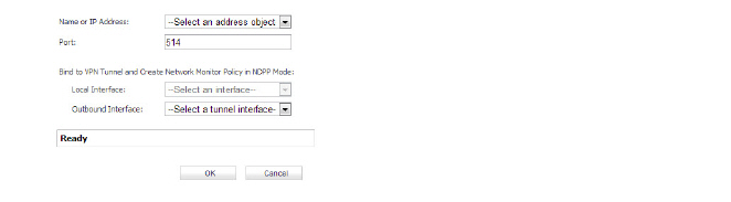
When configuring a VPN on an interface that is also configured for Layer 2 Bridge mode, you must configure an additional route to ensure that incoming VPN traffic properly traverses the SonicWALL security appliance. Navigate to the Network > Routing page, in the Route Policies section, click on the Add button. In the Add Route Policy window, configure the route as follows:
• Source: ANY
• Destination: custom-VPN-address-object (This is the address object for the local VPN tunnel IP address range.)
• Service: ANY
• Gateway: 0.0.0.0
• Interface: X0
Virtual Access Point Layer 2 Bridge
The Virtual Access Point (VAP) Layer 2 Bridge feature enables network administrators to bridge a wireless interface zone to a wired interface zone. The VAP Layer 2 Bridge is based on the WLAN Layer 2 bridge and the wireless VAP and makes it much easier to deploy a combined wireless and wired network.
All devices on a VAP Layer 2 Bridge share the same subnet and can forward broadcast packets. On a wired interface Layer 2 Bridge, all packets with VLAN tags are forwarded to the bridge-partner interface (the interface with the same VLAN address).
A VLAN subinterface does not support Layer 2 Bridge mode. However, the VAP Layer 2 Bridge feature supports Layer 2 bridges for subinterfaces when the interface zone is a WLAN zone.
When a VAP Layer 2 Bridge is configured, wireless clients on VAP interfaces share the same subnet with the primary bridge interface.
Key Concepts of VAP Layer 2 Bridge
• Bridged-Pair—two logical interfaces composed of a primary bridge interface and a secondary bridge interface. Primary and secondary does not indicate the level dominance or subordination. Both interfaces function according to their zone type and pass IP traffic according to their configured access rules. Each bridge-pair requires two physical interfaces. The number of bridge-pairs available is half the number of physical interfaces on the appliance. Non-IPv4 traffic across a bridge-pair is controlled by the “Block All Non-IPV4 Traffic” setting on the secondary bridge interface.
• Primary Bridge Interface—The designation assigned to an interface after a secondary bridge interface is paired to it. A primary bridge interface may belong to any of these zones:
– Untrusted (WAN)
– Trusted (LAN)
– Public (DMZ)
• Secondary Bridge Interface—The designation assigned to an interface whose IP assignment is configured for Layer 2 Bridge Mode. A secondary bridge interface may belong to any of these zones:
– Trusted (LAN)
– Public (DMZ)
– WLAN
• Bridged-Partner—the term that refers to the other member of a bridge-pair. This can be the primary bridge interface or the secondary bridge interface.
• Non-IPv4 Traffic—SonicOS Enhanced supports the following IP protocol types: ICMP, IGMP, TCP, UDP, GRE, ESP, AH, EIGRP, OSPF, PIM-SM, L2TP
Other IP types, such as Combat Radio Transport Protocol and non-IPv4 traffic types such as IPX and IPv6, are not natively handled by the SonicOS. The Layer 2 Bridge Mode can be configured to pass or drop non-IPv4 traffic.
• Captive-Bridge Mode—an optional mode for a Layer 2 Bridge that prevents traffic from being forwarded through a non-bridge-pair interface instead of through the Layer 2 Bridge. By default, a Layer 2 Bridge forwards all traffic to its destination through the most optimal path as determined by ARP and the routing tables. In some cases, traffic may be forwarded through a non-bridge-pair interface. When a Layer 2 Bridge is set to captive-bridge mode, all traffic that enters the Layer 2 Bridge is forced to exit through the Layer 2 Bridge rather than taking another route, such as through a non-bridge-pair interface, even though that may be the optimal path. In general, Captive-Bridge Mode is only required in complex networks with redundant paths, where strict path adherence is required.
• Virtual Access Point (VAP)—a VAP is a multiplexed instantiation of a single physical Access Point (AP) so that it presents itself as multiple discrete Access Points. To WLAN clients, each VAP appears to be an independent physical AP, when in actuality there is only a single physical AP. For WLANs operating in Layer 2 Bridge Mode, a VAP is a WLAN zone subinterface.
Setting a WLAN Zone to Layer 2 Bridged Mode
In addition to being able to support static IP address assignment on a WLAN zone interface, you can also bridge a WLAN zone interface to another interface. When a WLAN interface is bridged to a LAN/DMZ interface, the LAN/DMZ interface becomes the primary bridge interface, and the WLAN interface becomes the secondary bridged interface, as illustrated below:
• Zone: set to WLAN
• IP Assignment: set to Layer 2 Bridged Mode
• Parent Interface: is X4:V1, which is the WLAN interface on which this dialog was opened.
• Bridged to: is set to X5:100, which is the LAN interface.
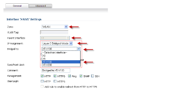
When you set the IP Assignment to Layer 2 Bridge Mode, the WLAN interface becomes the secondary bridge interface to the primary bridge interface to which it is paired in the Bridged to: box. In this case, the WLAN interface, X4:V1, becomes the secondary bridge interface, and the LAN interface, X5:V100, becomes the primary bridge interface.
The resulting Bridge-Pair is a two-port learning bridge with full Layer 2 transparency. All IP traffic that passes though the bridge is subjected to a full stateful, deep-packet inspection.
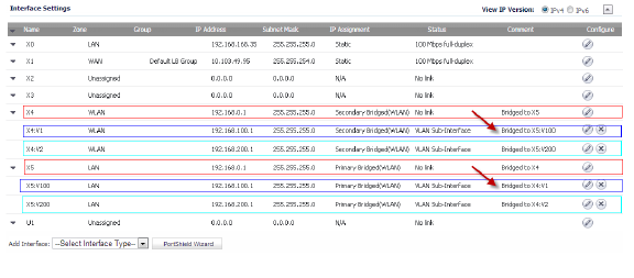
After the Bridge-Pair is created, the Network > Interfaces screen displays the primary and secondary bridge interface designations as shown in this graphic.
To set a WLAN zone to Layer 2 Bridge Mode:
1. On the SonicWall Security appliance, go to Network > Interfaces.
2. On the interface you want to set to Layer 2 Bridge Mode, click the Configure icon.
(This interface becomes the secondary bridge interface.)
3. In the Interface Settings dialog, set the Zone to WLAN.
4. Set the Mode / IP Assignment box to Layer 2 Bridge Mode.
5. Set the Bridged to: box to the interface you want.
(This interface becomes the primary bridge interface.)
Address Resolution Protocol
Layer 2 Bridge Mode employs a secure learning bridge architecture, enabling it to pass and inspect traffic types that cannot be handled by many other methods of transparent security appliance integration.
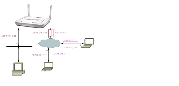
On a Layer 2 Bridge, Address Resolution Protocol (ARP) is used to determine the addresses of the interfaces in the bridge-pair. The Layer 2 Bridge Mode ARP dynamically determines which hosts are on which interfaces of a Layer 2 Bridge. ARP data is passed through a Layer 2 Bridge natively, so a host communicating across a Layer 2 Bridge sees the host MAC addresses of its peers and not the IP addresses.
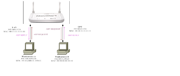
For example, Workstation A communicates with a Sonicwall Security Appliance (192.168.0.1) and Workstation B (192.168.0.200). Workstation A sees the Sonicwall Security Appliance as 00:11:11:11:11:11 and Workstation B as 00:90:10:10:10:10.
For wireless interfaces in AP mode or WLAN zone interfaces connecting SonicPoints, ARP packets are forwarded only to the WLAN zone interface for inner-client communication.
For WLAN zone interfaces in Layer 2 Bridge mode, ARP packets are forwarded to both bridge-pair interfaces.
The following diagram shows the ARP packet path on a WLAN zone bridged interface:
Wireless Address Objects
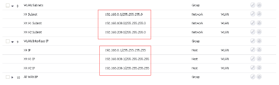
In wireless mode, after bridging the wireless (WLAN) interface to a LAN/DMZ zone, the WLAN zone becomes the secondary bridged interface, allowing wireless clients to share the same subnet and DHCP pool as their wired counterparts. For wireless interfaces set to Layer 2 Bridge mode, the WLAN interface address objects have the same IP address as the primary bridge interface.
This graphic shows three wireless address objects for WLAN subnets and three for WLAN Interface IP. The WLAN zone objects are on the secondary bridge interface and should have the same IP addresses as the primary bridge interface. The primary bridge interface IP addresses are 192.168.0.1, 192.168.100.1, and 192.168.200.1.
DHCP Support
When a WLAN zone operates in Layer 2 Bridge Mode, a DHCP server is not allowed on the primary bridge interface or the secondary bridge interface. DHCP may only be passed through the bridge-pair. However, wireless clients can get their IP addresses from DHCP.
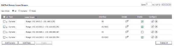
When a WLAN zone operates in Static IP Mode, a default DHCP lease scope is automatically created. If a wireless interface is bridged to another interface, the wireless client gets its IP address from the primary interface DHCP.
This graphic shows the DHCP lease scopes for WLAN interfaces in Layer 2 Bridge Mode.
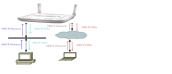
If a bridge-pair does not include a WLAN zone interface, DHCP is passed through the bridge-pair. The SonicOS acts as a DHCP server for WLAN zone interfaces. A DHCP packet received on WLAN zone interface is terminated at the box and passed to the DHCP task. The following graphic shows the DHCP packet path.
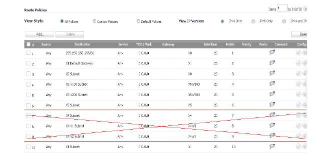
Route Policy
The route policy determines the interface on which packets are forwarded. In WLAN Layer 2 Bridge mode, packets are sent to the primary interface subnet. Then the system searches the ARP hash table for the IP address of an egress interface operating in Layer 2 Bridge mode and sends the packet out that interface.
In the route policy table shown in this graphic, the Layer 2 Bridge-Pair consists of item numbers 4 through 9. Interface X5 is the primary bridge interface and Interface X4 is the secondary bridge interface. Both interfaces have the same Gateway IP address. So, the route policy for the secondary interface is automatically removed by the system. This graphic shows which route policy is removed.
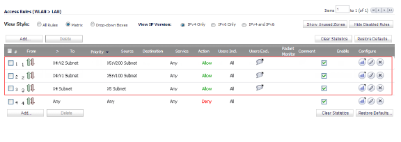
Access Rules
Allow Access Rules for WLAN Layer 2 Bridges are automatically added to the primary bridge interface of a bridge-pair. For example, when you add an Allow Access Rule for a WLAN Layer 2 Bridge, the same Allow Access Rule is automatically added to the DMZ/LAN zone. Also, when an Allow Access Rule is deleted from a WLAN zone, it is also deleted from the corresponding DMZ/LAN zone. The following graphic shows an example of added Allow Access Rules.
Configuring IPS Sniffer Mode (SonicWALL NSA series appliances)
To configure the SonicWALL NSA appliance for IPS Sniffer Mode, you will use two interfaces in the same zone for the L2 Bridge-Pair. You can use any interfaces except the WAN interface. For this example, we will use X2 and X3 for the Bridge-Pair, and configure them to be in the LAN zone. The WAN interface (X1) is used by the SonicWALL appliance for access to the SonicWALL Data Center as needed. The mirrored port on the switch will connect to one of the interfaces in the Bridge-Pair.
This section contains the following topics:
• Configuration Task List for IPS Sniffer Mode
• Configuring the Primary Bridge Interface
• Configuring the Secondary Bridge Interface
• Enabling and Configuring SNMP
• Configuring Security Services (Unified Threat Management)
• Connecting the Mirrored Switch Port to a IPS Sniffer Mode Interface
• Connecting and Configuring the WAN Interface to the Data Center
Configuration Task List for IPS Sniffer Mode
1. Configure the Primary Bridge Interface
– Select LAN as the Zone for the Primary Bridge Interface
– Assign a static IP address
2. Configure the Secondary Bridge Interface
– Select LAN as the Zone for the Secondary Bridge Interface
– Enable the L2 Bridge to the Primary Bridge interface
3. Enable SNMP and configure the IP address of the SNMP manager system where traps can be sent
4. Configure Security Services (UTM) for LAN traffic
5. Configure logging alert settings to “Alert” or below
6. Connect the mirrored port on the switch to either one of the interfaces in the Bridge-Pair
7. Connect and configure the WAN to allow access to dynamic signature data over the Internet
Configuring the Primary Bridge Interface
1. Navigate to the Network > Interfaces page.
2. Click the Configure icon in the right column of interface X2.
3. In the Edit Interface dialog box on the General tab, select LAN from the Zone drop-down list.
Note that you do not need to configure settings on the Advanced or VLAN Filtering tabs.
4. For IP Assignment, select Static from the drop-down list.
5. Configure the interface with a static IP Address (e.g. 10.1.2.3). The IP address you choose should not collide with any of the networks that are seen by the switch.
Note The Primary Bridge Interface must have a static IP assignment.
6. Configure the Subnet Mask.
7. Type in a descriptive comment.
8. Select management options for the interface (HTTP, HTTPS, Ping, SNMP, SSH, User Logins, HTTP Redirects).
9. Click OK.
Configuring the Secondary Bridge Interface
Our example continues with X3 as the secondary bridge interface.
1. Navigate to the Network > Interfaces page.
2. Click the Configure icon in the right column of the X3 interface.
3. In the Edit Interface dialog box on the General tab, select LAN from the Zone drop-down list.
Note You do not need to configure settings on the Advanced or VLAN Filtering tabs.
4. In the Mode / IP Assignment drop-down list, select Layer 2 Bridged Mode.
5. In the Bridged to drop-down list, select the X2 interface.
6. Do not enable the Block all non-IPv4 traffic setting if you want to monitor non-IPv4 traffic.
7. Select Never route traffic on this bridge-pair to ensure that the traffic from the mirrored switch port is not sent back out onto the network. (The Never route traffic on this bridge-pair setting is known as Captive-Bridge Mode.)
8. Select Only sniff traffic on this bridge-pair to enable sniffing or monitoring of packets that arrive on the L2 Bridge from the mirrored switch port.
9. Select Disable stateful-inspection on this bridge-pair to exempt these interfaces from stateful high availability inspection. If Deep Packet Inspection services are enabled for these interfaces, the DPI services will continue to be applied.
10. Configure management (HTTP, HTTPS, Ping, SNMP, SSH, User Logins, HTTP Redirects).
11. Click OK.
When SNMP is enabled, SNMP traps are automatically triggered for many events that are generated by SonicWALL Security Services such as Intrusion Prevention and Gateway Anti-Virus.
More than 50 IPS and GAV events currently trigger SNMP traps. The SonicOS Log Event Reference Guide contains a list of events that are logged by SonicOS, and includes the SNMP trap number where applicable. The guide is available online at
http://www.sonicwall.com/us/Support.html by typing Log Event into the Search field at the top of the page.
To determine the traps that are possible when using IPS Sniffer Mode with Intrusion Prevention enabled, search for Intrusion in the table found in the Index of Log Event Messages section in the SonicOS Log Event Reference Guide. The SNMP trap number, if available for that event, is printed in the SNMP Trap Type column of the table.
To determine the possible traps with Gateway Anti-Virus enabled, search the table for Security Services, and view the SNMP trap number in the SNMP Trap Type column.
To enable and configure SNMP:
1. Navigate to the System > SNMP page.
2. Select the Enable SNMP checkbox, then click the Configure button.
The SNMP Settings dialog box is displayed:
3. In the SNMP Settings dialog box, for System Name, type the name of the SNMP manager system that will receive the traps sent from the SonicWALL.
4. Enter the name or email address of the contact person for the SNMP Contact
5. Enter a description of the system location, such as “3rd floor lab”.
6. Enter the system’s asset number.
7. For Get Community Name, type the community name that has permissions to retrieve SNMP information from the SonicWALL, e.g. public.
8. For Trap Community Name, type the community name that will be used to send SNMP traps from the SonicWALL to the SNMP manager, e.g. public.
9. For the Host fields, type in the IP address(es) of the SNMP manager system(s) that will receive the traps.
10. Click OK.
Configuring Security Services (Unified Threat Management)
The settings that you enable in this section will control what type of malicious traffic you detect in IPS Sniffer Mode. Typically you will want to enable Intrusion Prevention, but you may also want to enable other Security Services such as Gateway Anti-Virus or Anti-Spyware.
To enable Security Services, your SonicWALL must be licensed for them and the signatures must be downloaded from the SonicWALL Data Center. For complete instructions on enabling and configuring IPS, GAV, and Anti-Spyware, see the Security Services section in this guide.
You can configure logging to record entries for attacks that are detected by the SonicWALL.
To enable logging, perform the following steps:
1. Select the Log tab, Categories folder from the navigation panel.
2. Under Log Categories, select All Categories in the View Style drop-down list.
3. In the Attacks category, enable the checkboxes for Log, Alerts, and Syslog.
4. Click Apply.
Connecting the Mirrored Switch Port to a IPS Sniffer Mode Interface
Use a standard Cat-5 Ethernet cable to connect the mirrored switch port to either interface in the Bridge-Pair. Network traffic will automatically be sent from the switch to the SonicWALL where it can be inspected.
Consult the switch documentation for instructions on setting up the mirrored port.
Connecting and Configuring the WAN Interface to the Data Center
Connect the WAN port on the SonicWALL, typically port X1, to your gateway or to a device with access to the gateway. The SonicWALL communicates with the SonicWALL Data Center automatically. For detailed instructions on configuring the WAN interface, see Configuring a WAN Interface.
Configuring Wire Mode (SonicWALL NSA series appliances)
Adding to the broad collection of traditional modes of SonicOS interface operation, including all LAN modes (Static, NAT, Transparent Mode, L2 Bridge Mode, Portshield Switch Mode), and all WAN modes (Static, DHCP, PPPoE, PPTP, and L2TP), SonicOS 5.8 introduces Wire-Mode, which provides four new methods non-disruptive, incremental insertion into networks.
|
To summarize the key functional differences between modes of interface configuration:
|
|
Note When operating in Wire-Mode, the SonicWALL security appliance’s dedicated “Management” interface will be used for local management. To enable remote management and dynamic security services and application intelligence updates, a WAN interface (separate from the Wire-Mode interfaces) must be configured for Internet connectivity. This is easily done given that SonicOS supports interfaces in mixed-modes of almost any combination.
To configure an interface for Wire Mode, perform the following steps:
1. On the Network > Interfaces page, click the Configure button for the interface you want to configure for Wire Mode.
2. In the Zone pull-down menu, select LAN.
3. To configure the Interface for Tap Mode, in the Mode / IP Assignment pulldown menu, select Tap Mode (1-Port Tap) and click OK.
To configure the Interface for Wire Mode, in the Mode / IP Assignment pulldown menu, select Wire Mode (2-Port Wire).
In the Wire Mode Type pulldown menu, select the appropriate mode:
• Bypass Mode (via Internal Switch / Relay)
• Inspect Mode (Passive DPI of Mirrored Traffic)
• Secure Mode (Active DPI of Inline Traffic)
6. When Inspect Mode is selected, the Restrict analysis at resource limit option is displayed. It is enabled by default. When this option is enabled, the appliance scans the maximum number of packets it can process. The remaining packets are allowed to pass without inspection. If this option is disabled, traffic will be throttled in the flow of traffic exceeds the firewalls inspection ability.
Note Disabling the Restrict analysis at resource limit option will reduce throughput if the rate of traffic exceeds the appliance’s ability to scan all traffic.
7. In the Paired Interface pulldown menu, select the interface that will connect to the upstream firewall. The paired interfaces must be of the same type (two 1 GB interfaces or two 10 GB interfaces).
Note Only unassigned interfaces are available in the Paired Interface pulldown menu. To make an interface unassigned, click on the Configure button for it, and in the Zone pulldown menu, select Unassigned.
8. Click OK.
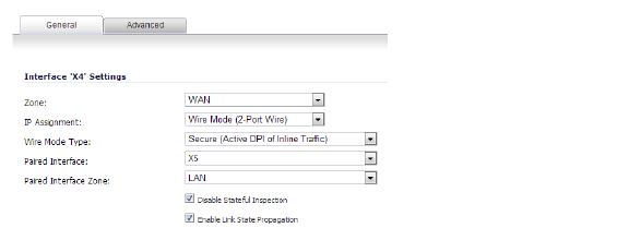
Configuring Wired Mode 2.0
Wire Mode 2.0 can be configured on any zone (except wireless zones). Wire Mode is a simplified form of Layer 2 Bridge Mode, and is configured as a pair of interfaces. In Wire Mode, the destination zone is the Paired Interface Zone. Access rules are applied to the Wire Mode pair based on the direction of traffic between the source Zone and its Paired Interface Zone. For example, if the source Zone is WAN and the Paired Interface Zone is LAN, then WAN to LAN and LAN to WAN rules are applied, depending on the direction of the traffic.
In Wire Mode, administrators can enable Link State Propagation, which propagates the link status of an interface to its paired interface. If an interface goes down, its paired interface is forced down to mirror the link status of the first interface. Both interfaces in a Wired Mode pair always have the same link status.
In Wire Mode, administrators can Disable Stateful Inspection. When Disable Stateful Inspection is selected, Stateful Packet Inspection (SPI) is turned off. When Disable Stateful Inspection is not selected, new connections can be established without enforcing a 3-way TCP handshake. Disable Stateful Inspection must be selected if asymmetrical routes are deployed.
When the Bypass when SonicOS is restarting or down option is selected, and the Wire Mode Type is set to Secure, traffic continues to flow even when the SonicWALL Security Appliance is rebooting or is down. The Bypass when SonicOS is restarting or down option is always enabled and is not editable when Disable Stateful Inspection is selected.
To configure Wire Mode 2.0, perform the following:
1. On the SonicWALL Security Appliance, go to Network > Interfaces.
2. Click the Add Interface button.
or
Click the Configure button for the interface you want to configure.
3. Under the General tab, in the IP Assignment list, select Wire Mode (2-Port Wire).
4. In the Zone list, select WAN.
5. In the Paired Interface Zone list, select LAN.
6. Select the Enable Link State Propagation option.
7. Select the Disable Stateful Inspection option.
8. Click the OK button.
Configuring Interfaces for IPv6
![]() For complete information on SonicWALL’s implementation of IPv6, see the Appendix C: IPv6 Appendix.
For complete information on SonicWALL’s implementation of IPv6, see the Appendix C: IPv6 Appendix.
IPv6 interfaces are configured on the Network > Interfaces page by clicking the IPv6 option for the View IP Version radio button at the top right corner of the page.
By default, all IPv6 interfaces appear as routed with no IP address. Multiple IPv6 addresses can be added on the same interface. Auto IP assignment can only be configured on WAN interfaces.
Each interface can be configured to receive router advertisement or not. IPv6 can be enabled or disabled on each interface.
The zone assignment for an interface must be configured through the IPv4 interface page before switching to IPv6 mode