On the
High Availability > Monitoring
page, you can configure both physical and logical interface monitoring. By enabling physical interface monitoring, you enable link detection for the designated HA interfaces. The link is sensed at the physical layer to determine link viability. Logical monitoring involves configuring the SonicWALL to monitor a reliable device on one or more of the connected networks. Failure to periodically communicate with the device by the Active unit in the HA Pair will trigger a failover to the Idle unit. If neither unit in the HA Pair can connect to the device, no action will be taken.
The Primary and Backup IP addresses configured on this page are used for multiple purposes:
Configuring unique management IP addresses for both units in the HA Pair allows you to log in
to each unit independently for management purposes. Note that non-management traffic is ignored if it is sent to one of these IP addresses. The Primary and Backup SonicWALL security appliances’ unique LAN IP addresses cannot act as an active gateway; all systems connected to the internal LAN will need to use the virtual LAN IP address as their gateway.
The management IP address of the Backup/Idle unit is used to allow license synchronization
with the SonicWALL licensing server, which handles licensing on a per-appliance basis (not per-HA Pair). Even if the Backup unit was already registered on MySonicWALL before creating the HA association, you must use the link on the System
> Licenses
page to connect to the SonicWALL server while accessing the Backup appliance through its management IP address.
When using logical monitoring, the HA Pair will ping the specified Logical Probe IP address
target from the Primary as well as from the Backup SonicWALL. The IP address set in the Primary IP Address or Backup IP Address field is used as the source IP address for the ping. If both units can successfully ping the target, no failover occurs. If both cannot successfully ping the target, no failover occurs, as the SonicWALLs will assume that the problem is with the target, and not the SonicWALLs. But, if one SonicWALL can ping the target but the other SonicWALL cannot, the HA Pair will failover to the SonicWALL that can ping the target.
The configuration tasks on the
High Availability
> Monitoring
page are performed on the Primary unit and then are automatically synchronized to the Backup.
To set the independent LAN management IP addresses and configure physical and/or logical
interface monitoring, perform the following steps:
|
Step 3
|
Click the
Configure
icon for an interface on the LAN, such as X0
.
|
|
Step 5
|
In the
Primary IP Address
field, enter the unique LAN management IP address of the Primary unit.
|
|
Step 6
|
In the
Backup IP Address
field, enter the unique LAN management IP address of the Backup unit.
|
|
Step 7
|
Select the
Allow Management on Primary/Backup IP Address
checkbox. When this option is enabled for an interface, a green icon appears in the interface’s Management column in the Monitoring Settings table on the High Availability > Monitoring page. Management is only allowed on an interface when this option is enabled.
|
|
Step 8
|
In the
Logical Probe IP Address
field, enter the IP address of a downstream device on the LAN network that should be monitored for connectivity. Typically, this should be a downstream router or server. (If probing is desired on the WAN side, an upstream device should be used.) The Primary and Backup appliances will regularly ping this probe IP address. If both can successfully ping the target, no failover occurs. If neither can successfully ping the target, no failover occurs, because it is assumed that the problem is with the target, and not the SonicWALL appliances. But, if one appliance can ping the target but the other appliance cannot, failover will occur to the appliance that can ping the target.
|
The
Primary IP Address
and Backup IP Address
fields must be configured with independent IP addresses on a LAN interface, such as X0, (or a WAN interface, such as X1, for probing on the WAN) to allow logical probing to function correctly.
When the
Enable Virtual MAC
checkbox is selected on the High Availability> Advanced
page, the SonicOS firmware automatically generates a Virtual MAC address for all interfaces. Allowing the SonicOS firmware to generate the Virtual MAC address eliminates the possibility of configuration errors and ensures the uniqueness of the Virtual MAC address, which prevents possible conflicts.
Once you finish configuring the High Availability settings on the Primary SonicWALL security
appliance and click the Accept
button, the Primary will automatically synchronize the settings to the Backup unit, causing the Backup to reboot. You do not need to click the Synchronize
Settings
button.
Later, when you click
Synchronize Settings
, it means that you are initiating a full manual synchronization and the Backup will reboot after synchronizing the preferences. You should see a HA Peer Firewall has been updated
message at the bottom of the management interface page. Note that the regular Primary-initiated synchronization (automatic, not manual) is an incremental sync, and does not cause the Backup to reboot.
By default, the
Include Certificate/Keys
setting is enabled. This specifies that Certificates, CRLs and associated settings (such as CRL auto-import URLs and OCSP settings) are synchronized between the Primary and Backup units. When Local Certificates are copied to the Backup unit, the associated Private Keys are also copied. Because the connection between the Primary and Backup units is typically protected, this is generally not a security concern.
To verify that Primary and Backup SonicWALL security appliances are functioning correctly,
wait a few minutes, then power off the Primary SonicWALL device. The Backup SonicWALL security appliance should quickly take over.
From your management workstation, test connectivity through the Backup SonicWALL by
accessing a site on the public Internet – note that the Backup SonicWALL, when Active, assumes the complete identity of the Primary, including its IP addresses and Ethernet MAC addresses.
Log into the Backup SonicWALL’s unique LAN IP address. The management interface should
now display Logged Into: Backup SonicWALL Status: (green ball) Active
in the upper right corner. If all licenses are not already synchronized with the Primary unit, navigate to the System > Licenses page and register this SonicWALL security appliance on mysonicwall.com. This allows the SonicWALL licensing server to synchronize the licenses.
Now, power the Primary SonicWALL back on, wait a few minutes, then log back into the
management interface. The management interface should again display Logged Into: Primary
SonicWALL Status: (green ball) Active
in the upper right corner.
If you are using the Monitor Interfaces feature, experiment with disconnecting each monitored
link to ensure that everything is working correctly.
Successful High Availability synchronization is not logged, only failures are logged.
In some cases, it may be necessary to force a transition from the Active SonicWALL to the Idle
unit – for example, to force the Primary SonicWALL to become Active again after a failure when Preempt Mode
has not been enabled, or to force the Backup SonicWALL to become Active in order to do preventive maintenance on the Primary SonicWALL.
To force such a transition, it is necessary to interrupt the heartbeat from the currently Active
SonicWALL. This may be accomplished by disconnecting the Active SonicWALL’s LAN port, by shutting off power on the currently Active unit, or by restarting it from the Web management interface. In all of these cases, heartbeats from the Active SonicWALL are interrupted, which forces the currently Idle
unit to become Active
.
To restart the Active SonicWALL, log into the Primary SonicWALL LAN IP address and click
System
on the left side of the browser window and then click Restart
at the top of the window.
Click
Restart SonicWALL
, then Yes
to confirm the restart. Once the Active SonicWALL restarts, the other SonicWALL in the High Availability
pair takes over operation.
When your SonicWALL security appliances have Internet access, each appliance in a High
Availability Pair must be individually registered from the SonicOS management interface while the administrator is logged into the individual management IP address of each appliance. This allows the Backup unit to synchronize with the SonicWALL licensing server and share licenses with the associated Primary appliance. There is also a way to synchronize licenses for an HA Pair whose appliances do not have Internet access.
When live communication with SonicWALL's licensing server is not permitted due to network policy,
you can use license keysets to manually apply security services licenses to your appliances. When you register a SonicWALL security appliance on MySonicWALL, a license keyset is generated for the appliance. If you add a new security service license, the keyset is updated. However, until you apply the licenses to the appliance, it cannot perform the licensed services.
You can use one of the following procedures to apply licenses to an appliance:
Follow the procedure in this section to activate licenses from within the SonicOS user interface.
Perform the procedure for each of the appliances in a High Availability Pair while logged into its individual LAN management IP address. See “
High Availability > Monitoring
”
to configure the individual IP addresses.
|
Step 2
|
On the
System
> Licenses
page, under Manage Security Services Online
, click the link for To Activate, Upgrade or Renew services, click here
.
|
|
Step 3
|
In the
Licenses
> License Management
page, type your MySonicWALL user name and password into the text boxes.
|
|
Step 5
|
On the
Systems
> Licenses
page under Manage Security Services Online
, verify the services listed in the Security Services Summary
table.
|
You can follow the procedure in this section to view the license keyset on MySonicWALL and
copy it to the SonicWALL security appliance. Perform the procedure for each of the appliances in a High Availability Pair while logged into its individual LAN management IP address. See “
High Availability > Monitoring
”
to configure the individual IP addresses.
|
Step 3
|
On the
My Products
page, under Registered Products
, scroll down to find the appliance to which you want to copy the license keyset. Click the product name
or serial number
.
|
|
Step 4
|
On the
Service Management
page, click View License keyset
.
|
|
Step 5
|
On the
License Keyset
page, use your mouse to highlight all the characters in the text box.
|
This is the license keyset for the SonicWALL security appliance that you selected in
Step 3
.
|
Step 8
|
On the
Systems
> Licenses
page under Manual Upgrade
, press Ctrl+V
to paste the license keyset into the Or enter keyset
text box.
|
There are several ways to view High Availability status in the SonicOS Enhanced management
interface. See the following sections:
The
High Availability Status
table on the High Availability
> Settings
page displays the current status of the HA Pair. If the Primary SonicWALL is Active, the first line in the table indicates that the Primary SonicWALL is currently Active.
It is also possible to check the status of the Backup SonicWALL by logging into the unique LAN
IP address of the Backup SonicWALL. If the Primary SonicWALL is operating normally, the status indicates that the Backup SonicWALL is currently Idle. If the Backup has taken over for the Primary, the status table indicates that the Backup is currently Active.
In the event of a failure in the Primary SonicWALL, you can access the management interface
of the Backup SonicWALL at the Primary SonicWALL virtual LAN IP address or at the Backup SonicWALL LAN IP address. When the Primary SonicWALL restarts after a failure, it is accessible using the unique IP address created on the High Availability > Monitoring page. If preempt mode is enabled, the Primary SonicWALL becomes the Active firewall and the Backup firewall returns to Idle status.
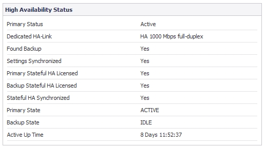
The table displays the following information:
|
|
•
|
Primary Status
– This field is labeled Backup Status
when viewed on the Backup appliance. The possible values are:
|
|
|
–
|
Active
– Indicates that this appliance is in the ACTIVE state.
|
|
|
–
|
Idle
– Indicates that this appliance is in the IDLE state.
|
|
|
–
|
Disabled
– Indicates that High Availability has not been enabled in the management interface of this appliance.
|
|
|
–
|
Not in a steady state
– Indicates that HA is enabled and the appliance is neither in the ACTIVE nor the IDLE state.
|
|
|
•
|
Dedicated HA-Link
– Indicates the port, speed, and duplex settings of the HA link, such as HA 1000 Mbps full-duplex
, when two SonicWALL NSA E-Class appliances are connected over their dedicated HA interfaces. On a SonicWALL NSA appliance that does not have a dedicated HA interface, this field displays the designated interface, such as X5
, instead of HA
. When the HA interfaces are not connected or the link is down, the field displays the status in the form X5 No Link
. When High Availability is not enabled, the field displays Disabled
.
|
|
|
•
|
Found Backup
- Indicates Yes
if the Primary appliance has detected the Backup appliance, and No
if there is no HA link or if the Backup is rebooting. This field is labeled Found Primary
when viewed on the Backup appliance, and indicates Yes
if the Backup appliance has detected the Primary appliance, and No
if there is no HA link or if the Primary is rebooting.
|
|
|
•
|
Settings Synchronized
- Indicates if the settings are synchronized between the two appliances. This includes all settings that are part of the system preferences, for example, NAT policies, routes, user accounts. Possible values are Yes
or No
.
|
|
|
•
|
Backup Stateful HA Licensed
- Indicates if the Backup appliance has a stateful HA license. Possible values are Yes
or No
. Note that the Stateful HA license is shared with the Primary, but that you must access mysonicwall.com while logged into the LAN management IP address of the Backup unit in order to synchronize with the SonicWALL licensing server.
|
|
|
•
|
Stateful HA Synchronized
- Indicates if the Idle appliance is synchronized with the initial state of the Active appliance (TCP sessions, VPN tunnels) when they discover each other. The possible values are Yes
and No
. No
could mean that the stateful synchronization process for the initial state is in progress. Note that No
is also displayed if Stateful HA is not enabled or licensed on either of the units.
|
|
|
•
|
Primary State
- Indicates the current state of the Primary appliance as a member of an HA Pair. The Primary State field is displayed on both the Primary and the Backup appliances. The possible values are:
|
|
|
–
|
ACTIVE
–
Indicates that the Primary unit is handling all the network traffic except management/monitoring/licensing traffic destined to the IDLE unit.
|
|
|
–
|
IDLE
–
Indicates that the Primary unit is passive and is ready to take over on a failover.
|
|
|
–
|
ELECTION
–
Indicates that the Primary and Backup units are negotiating which should be the ACTIVE unit.
|
|
|
–
|
SYNC
–
Indicates that the Primary unit is synchronizing settings or firmware to the Backup.
|
|
|
–
|
ERROR
–
Indicates that the Primary unit has reached an error condition.
|
|
|
–
|
REBOOT
–
Indicates that the Primary unit is rebooting.
|
|
|
–
|
NONE
–
When viewed on the Primary unit, NONE
indicates that HA is not enabled on the Primary. When viewed on the Backup unit, NONE
indicates that the Backup unit is not receiving heartbeats from the Primary unit.
|
|
|
•
|
Backup State
- Indicates the current state of the Backup appliance as a member of an HA Pair. The Backup State field is displayed on both the Primary and the Backup appliances. The possible values are:
|
|
|
–
|
ACTIVE
–
Indicates that the Backup unit is handling all the network traffic except management/monitoring/licensing traffic destined to the IDLE unit.
|
|
|
–
|
IDLE
–
Indicates that the Backup unit is passive and is ready to take over on a failover.
|
|
|
–
|
ELECTION
–
Indicates that the Backup and Primary units are negotiating which should be the ACTIVE unit.
|
|
|
–
|
SYNC
–
Indicates that the Backup unit is synchronizing settings or firmware to the Primary.
|
|
|
–
|
ERROR
–
Indicates that the Backup unit has reached an error condition.
|
|
|
–
|
REBOOT
–
Indicates that the Backup unit is rebooting.
|
|
|
–
|
NONE
–
When viewed on the Backup unit, NONE
indicates that HA is not enabled on the Backup. When viewed on the Primary unit, NONE
indicates that the Primary unit is not receiving heartbeats from the Backup unit.
|
|
|
•
|
Active Up Time
- Indicates how long the current Active firewall has been Active, since it last became Active. This line only displays when High Availability is enabled. If failure of the Primary SonicWALL occurs, the Backup SonicWALL assumes the Primary SonicWALL LAN and WAN IP addresses. There are three main methods to check the status of the High Availability Pair: the High Availability Status window, Email Alerts and View Log. These methods are described in the following sections.
|
|
|
•
|
High Availability Status
- One method to determine which SonicWALL is Active is to check the High Availability Settings Status indicator on the High Availability > Settings
page. If the Primary SonicWALL is Active, the first line in the page indicates that the Primary SonicWALL is currently Active. It is also possible to check the status of the Backup SonicWALL by logging into the LAN IP address of the Backup SonicWALL. If the Primary SonicWALL is operating normally, the status indicates that the Backup SonicWALL is currently Idle. If the Backup has taken over for the Primary, the status indicates that the Backup is currently Active. In the event of a failure in the Primary SonicWALL, you can access the management interface of the Backup SonicWALL at the Primary SonicWALL LAN IP address or at the Backup SonicWALL LAN IP address. When the Primary SonicWALL restarts after a failure, it is accessible using the third IP address created during configuration. If preempt mode is enabled, the Primary SonicWALL becomes the Active firewall and the Backup firewall returns to Idle status.
|
If you have configured the Primary SonicWALL to send email alerts, you receive alert emails
when there is a change in the status of the High Availability Pair. For example, when the Backup SonicWALL takes over for the Primary after a failure, an email alert is sent indicating that the Backup has transitioned from Idle to Active. If the Primary SonicWALL subsequently resumes operation after that failure, and Preempt Mode has been enabled, the Primary SonicWALL takes over and another email alert is sent to the administrator indicating that the Primary has preempted the Backup.
The SonicWALL also maintains an event log that displays the High Availability events in
addition to other status messages and possible security threats. This log may be viewed in the SonicOS management interface or it may be automatically sent to the administrator’s email address. To view the SonicWALL log, click Log
on the left navigation pane of the management interface.
This section describes two methods of verifying the correct configuration of Active/Active UTM,
and two “false negatives” that might give the impression that the idle unit is not contributing.
See the following:
As soon as Active/Active UTM is enabled on the Stateful HA pair, you can observe a change in
CPU utilization on both appliances. CPU activity goes down on the active unit, and goes up on the idle unit.
To view and compare CPU activity:
|
Step 1
|
In two browser windows, log into the
Monitoring
IP address of each unit, active and idle. For information about configuring HA Monitoring, including individual IP addresses, see the SonicOS Enhanced Administrator’s Guide
.
|
|
Step 2
|
Navigate to the
System > Diagnostics
page in both SonicOS management interfaces.
|
|
Step 3
|
On both appliances, select
Multi-Core Monitor
from the Diagnostic Tool
drop-down list. The active unit is displayed below with the real-time Multi-Core Utilization graph showing an immediate drop in CPU activity.
|

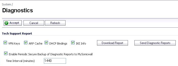
You can tell that Active/Active UTM is correctly configured on your Stateful HA pair by
generating a Tech Support Report on the System > Diagnostics page. The following configuration parameters should appear with their correct values in the Tech Support Report:
To generate a TSR for this purpose:
Responses, or actions, are always sent out from the active unit of the Stateful HA pair running
Active/Active UTM when DPI UTM matches are found in network traffic. Note that this does not indicate that all the processing was performed on the active unit.
Deep Packet Inspection discovers network traffic that matches virus attachments, IPS
signatures, Application Firewall policies, and other malware. When a match is made, SonicOS Enhanced performs an action such as dropping the packet or resetting the TCP connection.
Some DPI match actions inject additional TCP packets into the existing stream. For example,
when an SMTP session carries a virus attachment, SonicOS sends the SMTP client a “552” error response code, with a message saying “the email attachment contains a virus.” A TCP reset follows the error response code and the connection is terminated.
These additional TCP packets are generated as a result of the DPI UTM processing on the idle
firewall. The generated packets are sent to the active firewall over the HA data interface, and are sent out from the active firewall as if the processing occurred on the active firewall. This ensures seamless operation and it appears as if the DPI UTM processing was done on the active firewall.
If DPI UTM processing on the idle firewall results in a DPI match action as described above,
then the action is logged on the active unit of the Stateful HA pair, rather than on the idle unit where the match action was detected. This does not indicate that all the processing was performed on the active unit.