For general information on NAT Policies, see
Network > NAT Policies
.
NAT policies allow you the flexibility to control Network Address Translation based on matching
combinations of Source IP address, Destination IP address, and Destination Services. Policy-based NAT allows you to deploy different types of NAT simultaneously. This section contains the following subsections:
For this chapter, the examples use the following IP addresses as examples to demonstrate the
NAT policy creation and activation. You can use these examples to create NAT policies for your network, substituting your IP addresses for the examples shown here:
|
|
•
|
X0
IP address is 192.168.10.1
|
|
|
•
|
X1
IP address is 67.115.118.68
|
|
|
•
|
X2
‘Sales’ IP address is 192.168.30.1
|
Many-to-One is the most common NAT policy on a firewall, and allows you to translate a group
of addresses into a single address. Most of the time, this means that you’re taking an internal “private” IP subnet and translating all outgoing requests into the IP address of the WAN interface of the firewall (by default, the X1 interface), such that the destination sees the request as coming from the IP address of the firewall WAN interface, and not from the internal private IP address.
This policy is easy to set up and activate. From the Management Interface, go to the
Network
> NAT Policies
page and click on the Add
button. The Add NAT Policy
window is displayed for adding the policy. To create a NAT policy to allow all systems on the X2
interface to initiate traffic using the firewall’s WAN IP address, choose the following from the drop-down boxes:
|
|
•
|
Comment
: Enter a short description
|
When done, click on the
OK
button to add and activate the NAT Policy. This policy can be duplicated for subnets behind the other interfaces of the firewall – just replace the Original
Source
with the subnet behind that interface, adjust the source interface, and add another NAT policy.
The Many-to-Many NAT policy allows you to translate a group of addresses into a group of
different addresses. This allows the firewall to utilize several addresses to perform the dynamic translation. Thus allowing a much higher number of concurrent the firewall to perform up to a half-million concurrent connections across the interfaces.
This policy is easy to set up and activate. You first need to go to the
Network > Address
Objects
and click on the Add
button at the bottom of the screen. When the Add Address
Object
window appears, enter in a description for the range in the Name
field, choose Range
from the drop-down menu, enter the range of addresses (usually public IP addresses supplied by your ISP) in the Starting IP Address
and Ending IP Address
fields, and select WAN
as the zone from the Zone Assignment
menu. When done, click on the OK
button to create the range object.
Select
Network > NAT Policies
and click on the Add
button. The Add NAT Policy window is displayed. To create a NAT policy to allow the systems on the LAN interface (by default, the X0 interface) to initiate traffic using the public range addresses, choose the following from the drop-down menus:
|
|
•
|
Comment
: Enter a short description
|
When done, click on the
OK
button to add and activate the NAT Policy. With this policy in place, the firewall dynamically maps outgoing traffic using the four available IP addresses in the range we created.
You can test the dynamic mapping by installing several systems on the LAN interface (by
default, the X0 interface) at a spread-out range of addresses (for example, 192.168.10.10, 192.168.10.100, and 192.168.10.200) and accessing the public Website http://www.whatismyip.com
from each system. Each system should display a different IP address from the range we created and attached to the NAT policy.
One-to-One NAT for outbound traffic is another common NAT policy on a firewall for translating
an internal IP address into a unique IP address. This is useful when you need specific systems, such as servers, to use a specific IP address when they initiate traffic to other destinations. Most of the time, a NAT policy such as this One-to-One NAT policy for outbound traffic is used to map a server’s private IP address to a public IP address, and it is paired with a reflective (mirror) policy that allows any system from the public Internet to access the server, along with a matching firewall access rule that permits this. Reflective NAT policies are covered in the next section.
This policy is easy to set up and activate. Select
Network > Address Objects
and click on the Add
button at the bottom of the screen. In the Add Address Object
window, enter a description for server’s private IP address in the Name
field. Choose Host from the Type
menu, enter the server’s private IP address in the IP Address
field, and select the zone that the server assigned from the Zone Assignment
menu. Click OK
. Then, create another object in the Add Address
Object
window for the server’s public IP address and with the correct values, and select WAN
from Zone Assignment
menu. When done, click on the OK
button to create the range object.
Next, select
Network > NAT Policies
and click on the Add
button to display the Add NAT
Policy
window. To create a NAT policy to allow the Web server to initiate traffic to the public Internet using its mapped public IP address, choose the following from the drop-down menus:
|
|
•
|
Comment
: Enter a short description
|
When done, click on the
OK
button to add and activate the NAT Policy. With this policy in place, the firewall translates the server’s private IP address to the public IP address when it initiates traffic out the WAN interface (by default, the X1 interface).
You can test the One-to-One mapping by opening up a Web browser on the server and
accessing the public Website http://www.whatismyip.com
. The Website should display the public IP address we attached to the private IP address in the NAT policy we just created.
This is the mirror policy for the one created in the previous section when you check
Create a
reflective policy
. It allows you to translate an external public IP addresses into an internal private IP address. This NAT policy, when paired with a ‘permit’ access policy, allows any source to connect to the internal server using the public IP address; the firewall handles the translation between the private and public address. With this policy in place, the firewall translates the server’s public IP address to the private IP address when connection requests arrive via the WAN interface (by default, the X1 interface).
Below, you create the entry as well as the rule to allow HTTP access to the server. You need
to create the access policy that allows anyone to make HTTP connections to the Web server via the Web server’s public IP address.
Go to the
Firewall > Access Rules
page and choose the policy for the ‘WAN’ to ‘Sales’ zone intersection (or, whatever zone you put your server in). Click on the ‘Add…’ button to bring up the pop-up access policy screen. When the pop-up appears, enter in the following values:
|
|
•
|
Comment
: (Enter a short description)
|
When you are done, attempt to access the Web server’s public IP address using a system
located on the public Internet. You should be able to successfully connect. If not, review this section, and the section before, and ensure that you have entered in all required settings correctly.
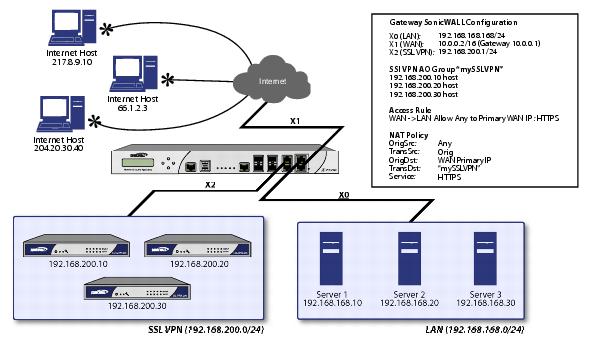
One-to-Many NAT policies can be used to persistently load balance the translated destination
using the original source IP address as the key to persistence. For example, firewalls can load balance multiple ADTRAN SSL VPN appliances, while still maintaining session persistence by always balancing clients to the correct destination SSL VPN. The following figure shows a sample topology and configuration.
To configure One-to-Many NAT load balancing, first go to the
Firewall > Access Rules
page and choose the policy for WAN
to LAN
. Click on the Add…
button to bring up the pop-up access policy screen. When the pop-up appears, enter in the following values:
|
|
•
|
Comment
: Descriptive text, such as SSLVPN LB
|
Next, create the following NAT policy by selecting
Network > NAT Policies
and clicking on the Add...
button:
|
|
–
|
Name
: A descriptive name, such as mySSLVPN
|
|
|
–
|
IP Address
: The IP addresses for the devices to be load balanced (in the topology shown above, this is 192.168.200.10, 192.168.200.20, and 192.168.200.30.)
|
|
|
•
|
Comment
: Descriptive text, such as SSLVPN LB
|
This type of NAT policy is useful when you want to conceal an internal server’s real listening
port, but provide public access to the server on a different port. In the example below, you modify the NAT policy and rule created in the previous section to allow public users to connect to the private Web server on its public IP address, but via a different port (TCP 9000), instead of the standard HTTP port (TCP 80).
|
Step 1
|
Create a custom service for the different port. Go to the
Firewall > Custom Services
page and select the Add
button. When the pop-up screen appears, give your custom service a name such as webserver_public_port
, enter in 9000
as the starting and ending port, and choose TCP(6)
as the protocol. When done, click on the OK
button to save the custom service.
|
|
|
•
|
Comment
: Enter a short description
|
|
|
Note
|
Make sure you chose
Any
as the destination interface, and not the interface that the server is on. This may seem counter-intuitive, but it is actually the correct thing to do (if you try to specify the interface, you get an error).
|
|
Step 3
|
When finished, click on the
OK
button to add and activate the NAT Policy. With this policy in place, the firewall translates the server’s public IP address to the private IP address when connection requests arrive from the WAN interface (by default, the X1 interface), and translates the requested protocol (TCP 9000) to the server’s actual listening port (TCP 80).
|
Finally, you’re going to modify the firewall access rule created in the previous section to allow
any public user to connect to the Web server on the new port (TCP 9000) instead of the server’s actual listening port (TCP 80).
Go to the
Firewall > Access Rules
section and choose the policy for the WAN
to Sales
zone intersection (or, whatever zone you put your server in). Click on the Configure
button to bring up the previously created policy. When the pop-up appears, edit in the following values:
|
|
•
|
Service
: server_public_port (or whatever you named it above)
|
|
|
•
|
Comment
: (enter a short description)
|
When you’re done, attempt to access the Web server’s public IP address using a system
located on the public Internet on the new custom port (example: http://67.115.118.70:9000). You should be able to successfully connect. If not, review this section, and the section before, and ensure that you have entered in all required settings correctly.
This is one of the more complex NAT policies you can create on a firewall running SonicOS
Enhanced – it allows you to use the WAN IP address of the firewall to provide access to multiple internal servers. This is most useful in situations where your ISP has only provided a single public IP address, and that IP address has to be used by the firewall’s WAN interface (by default, the X1 interface).
Below, you create the programming to provide public access to two internal Web servers via
the firewalls WAN IP address; each is tied to a unique custom port. In the following examples, you set up two, but it is possible to create more than these as long as the ports are all unique.
In this section, we have five tasks to complete:
|
Step 1
|
Create a custom service for the different port. Go to the
Firewall > Custom Services
page and click on the Add button. When the pop-up screen appears, give your custom services names such as servone_public_port
and servtwo_public_port
, enter in 9100
and 9200
as the starting and ending port, and choose TCP(6)
as the protocol. When done, click on the OK
button to save the custom services.
|
|
Step 2
|
Go to the
Network > Address
Objects
and click on the Add
button at the bottom of the page. In the Add Address Objects
window, enter in a description for server’s private IP addresses, choose Host
from the drop-down box, enter the server’s private IP addresses, and select the zone that the servers are in. When done, click on the OK
button to create the range object.
|
|
Step 3
|
Go to the
Network > NAT Policies
menu and click on the Add
button. The Add NAT Policy
window is displayed. To create a NAT policy to allow the two servers to initiate traffic to the public Internet using the firewall’s WAN IP address, choose the following from the drop-down boxes:
|
|
|
•
|
Comment
: Enter a short description
|
And:
|
|
•
|
Comment
: Enter a short description
|
When finished, click on the
OK
button to add and activate the NAT policies. With these policies in place, the firewall translates the servers’ private IP addresses to the public IP address when it initiates traffic out the WAN interface (by default, the X1 interface).
|
Step 4
|
Go to the
Network > NAT Policies
menu and click on the Add
button. The Add NAT Policy
window is displayed. To create the NAT policies to map the custom ports to the servers’ real listening ports and to map the ADTRAN’s WAN IP address to the servers’ private addresses, choose the following from the drop-down boxes:
|
|
|
•
|
Comment
: Enter a short description
|
And:
|
|
•
|
Comment
: Enter a short description
|
|
|
Note
|
Make sure you choose
Any
as the destination interface, and not the interface that the server is on. This may seem counter-intuitive, but it is actually the correct thing to do (if you try to specify the interface, you get an error).
|
When finished, click on the
OK
button to add and activate the NAT policies. With these policies in place, the firewall translates the server’s public IP address to the private IP address when connection requests arrive from the WAN interface (by default, the X1 interface).
Go to the
Firewall > Access Rules
page and choose the policy for the ‘WAN’ to ‘Sales’ zone intersection (or, whatever zone you put your serves in). Click on the ‘Add…’ button to bring up the pop-up window to create the policies. When the pop-up appears, enter the following values:
|
|
•
|
Service
: servone_public_port (or whatever you named it above)
|
|
|
•
|
Comment
: (enter a short description)
|
And:
|
|
•
|
Service
: servtwo_public_port (or whatever you named it above)
|
|
|
•
|
Comment
: (enter a short description)
|
When you’re finished, attempt to access the Web servers via the ADTRAN’s WAN IP address
using a system located on the public Internet on the new custom port (example:
http://67.115.118.70:9100 and http://67.115.118.70:9200). You should be able to successfully connect. If not, review this section, and the section before, and ensure that you have entered in all required settings correctly.
This section contains the following subsections:
The following figure shows the topology for the NAT load balancing network.
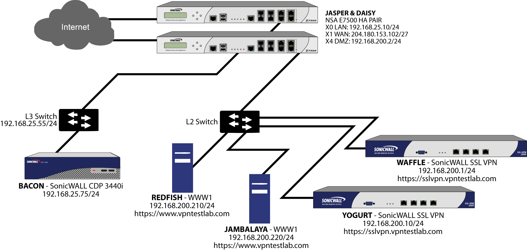
The examples shown in the
Tasklist
section on the next few pages utilize IP addressing information from a demo setup – please make sure and replace any IP addressing information shown in the examples with the correct addressing information for your setup. Also note that the interface names may be different.
To enable logging and alerting, log into the ADTRAN’s Management GUI, go to
Log >
Categories
, choose Debug
from the drop-down next to Logging Level
, chose All Categories
from the drop-down next to View Style
, check the boxes in the title bar next to Log
and Alerts
to capture all categories, and click on the Apply
button in the upper right hand corner to save and activate the changes. For an example, see the screenshot below. Debug logs should only be used for initial configuration and troubleshooting, and it is advised that once setup is complete, you set the logging level to a more appropriate level for your network environment.
To enable log name resolution, go to
Log > Name Resolution
, choose DNS then NetBIOS
from the Name Resolution Menu
drop-down list, and click on the Apply
button in the upper right hand corner to save and activate the changes.
To configure NAT load balancing, you must complete the following tasks:
To complete this configuration, perform the following steps:
|
Step 1
|
Create Network Objects --
Go to the Network > Address Objects
page in the Management GUI and create the network objects for both of the internal Web servers, and the Virtual IP (VIP) on which external users will access the servers.
|
|
Step 2
|
Create Address Group
-- Now create an address group named www_group
and add the two internal server address objects you just created.
|
|
Step 3
|
Create Inbound NAT Rule for Group --
Now create a NAT rule to allow anyone attempting to access the VIP to get translated to the address group you just created, using Sticky IP
as the NAT method.
|
|
Step 4
|
Set LB Type and Server Liveliness Method --
On the Advanced
tab of the NAT policy configuration control, you can specify that the object (or group of objects, or group of groups) be monitored via ICMP ping or by checking for TCP sockets opened. For this example, we are going to check to see if the server is up and responding by monitoring TCP port 80 (which is good, since that is what people are trying to access). You can now click on the OK
button to save and activate the changes.
|
|
Step 5
|
Create Outbound NAT Rule for LB Group --
Write a NAT rule to allow the internal servers to get translated to the VIP when accessing resources out the WAN interface (by default, the X1 interface).
|
|
Step 7
|
Test Your Work
–
From a laptop outside the WAN, connect via HTTP to the VIP using a Web browser.
|
If the Web servers do not seem to be accessible, go to the
Firewall > Access Rules
page and mouseover the Statistics
icon.
If the rule is configured incorrectly you will not see any Rx or TX Bytes; if it is working, you will
see these increment with each successful external access of the load balanced resources.You can also check the Firewall > NAT Policies
page and mouseover the Statistics
icon. If the policy is configured incorrectly you will not see any Rx or TX Bytes; if it is working, you will see these increment with each successful external access of the load balanced resources.
Finally, check the logs and the status page to see if there are any alerts (noted in yellow) about
the Network Monitor noting hosts that are offline; it may be that all of your load balancing resources are not reachable by the ADTRAN appliance and that the probing mechanism has marked them offline and out of service. Check the load balancing resources to ensure that they are functional and check the networking connections between them and the ADTRAN appliance.