The following sections provide information on VoIP settings:
For general information on VoIP, see
“VoIP Overview”
.
Configuring the SonicWALL security appliance for VoIP deployments builds on your basic
network configuration in the SonicWALL management interface. This chapter assumes the SonicWALL security appliance is configured for your network environment.
VoIP devices are supported on the following SonicOS zones:
SonicOS includes the VoIP configuration settings on the
VoIP > Settings
page. This page is divided into three configuration settings sections: General Settings
, SIP Settings
, and H.323
Settings
.
Consistent NAT enhances standard NAT policy to provide greater compatibility with peer-to-
peer applications that require a consistent IP address to connect to, such as VoIP. Consistent NAT uses an MD5 hashing method to consistently assign the same mapped public IP address and UDP Port pair to each internal private IP address and port pair.
For example, NAT could translate the private (LAN) IP address and port pairs, 192.116.168.10/
50650 and 192.116.168.20/50655 into public (WAN) IP/port pairs as follows:
With Consistent NAT enabled, all subsequent requests from either host 192.116.168.10 or
192.116.168.20 using the same ports illustrated in the previous result in using the same translated address and port pairs. Without Consistent NAT, the port and possibly the IP address change with every request.
To enable Consistent NAT, select the
Enable
Consistent NAT
setting and click Accept
. This checkbox is disabled by default.
By default, SIP clients use their private IP address in the SIP Session Definition Protocol (SDP)
messages that are sent to the SIP proxy. If your SIP proxy is located on the public (WAN) side of the SonicWALL security appliance and SIP clients are on the private (LAN) side behind the firewall, the SDP messages are not translated and the SIP proxy cannot reach the SIP clients.
Selecting
Enable SIP Transformations
transforms SIP messages between LAN (trusted) and WAN/DMZ (untrusted). You need to check this setting when you want the SonicWALL security appliance to do the SIP transformation. If your SIP proxy is located on the public (WAN) side of the SonicWALL and SIP clients are on the LAN side, the SIP clients by default embed/use their private IP address in the SIP/Session Definition Protocol (SDP) messages that are sent to the SIP proxy, hence these messages are not changed and the SIP proxy does not know how to get back to the client behind the SonicWALL. Selecting Enable SIP Transformations
enables the SonicWALL to go through each SIP message and change the private IP address and assigned port. Enable SIP Transformation
also controls and opens up the RTP/RTCP ports that need to be opened for the SIP session calls to happen. NAT translates Layer 3 addresses but not the Layer 7 SIP/SDP addresses, which is why you need to select Enable SIP Transformations to transform the SIP messages.
|
|
Tip
|
In general, you should check the
Enable SIP Transformations
box unless there is another NAT traversal solution that requires this feature to be turned off. SIP Transformations works in bi-directional mode, meaning messages are transformed going from LAN to WAN and vice versa.
|
Selecting
Permit non-SIP packets on signaling port
enables applications such as Apple iChat and MSN Messenger, which use the SIP signaling port for additional proprietary messages. Enabling this checkbox may open your network to malicious attacks caused by malformed or invalid SIP traffic. This checkbox is disabled by default.
The
Enable SIP Back-to-Back User Agent (B2BUA) support
setting should be enabled when the SonicWALL security appliance can see both legs of a voice call (for example, when a phone on the LAN calls another phone on the LAN). This setting should only be enabled when the SIP Proxy Server is being used as a B2BUA.
SIP Signaling inactivity time out (seconds)
and SIP Media inactivity time out (seconds)
define the amount of time a call can be idle (no traffic exchanged) before the SonicWALL security appliance denying further traffic. A call goes idle when placed on hold. The default time value for SIP Signaling inactivity time out
is 1800 seconds (30 minutes). The default time value for SIP Media inactivity time out
is
120 seconds (2 minutes).
The
Additional SIP signaling port (UDP) for transformations
setting allows you to specify a non-standard UDP port used to carry SIP signaling traffic. Normally, SIP signaling traffic is carried on UDP port 5060. However, a number of commercial VOIP services use different ports, such as 1560. Using this setting, the security appliance performs SIP transformation on these non-standard ports.
Select
Enable H.323 Transformation
in the H.323 Settings
section and click Accept
to
allow stateful H.323 protocol-aware packet content inspection and modification by the SonicWALL security appliance. The SonicWALL security appliance performs any dynamic IP address and transport port mapping within the H.323 packets, which is necessary for communication between H.323 parties in trusted and untrusted networks/zones. Disable the Enable H.323
Transformation
to bypass the H.323 specific processing performed by the SonicWALL security appliance.
Select
Only accept incoming calls from Gatekeeper
to ensure all incoming calls go through the Gatekeeper for authentication. The Gatekeeper will refuse calls that fail authentication.
Select
Enable LDAP ILS Support
to enable Microsoft NetMeeting users to locate and connect to users for conferencing and collaboration over the Internet.
The
H.323 Signaling/Media inactivity time out (seconds)
field specifies the amount of time a call can be idle before the SonicWALL security appliance denying further traffic. A call goes idle when placed on hold. The default time value for H.323 Signaling/Media inactivity time
out
is 300 seconds (5 minutes).
The
Default WAN/DMZ Gatekeeper IP Address
field has a default value of 0.0.0.0. Enter the default H.323 Gatekeeper IP address in this field to allow LAN-based H.323 devices to discover the Gatekeeper using the multicast address 225.0.1.41. If you do not enter an IP address, multicast discovery messages from LAN-based H.323 devices will go through the configured multicast handling.
One of the greatest challenges for VoIP is ensuring high speech quality over an IP network. IP
was designed primarily for asynchronous data traffic, which can tolerate delay. VoIP, however, is very sensitive to delay and packet loss. Managing access and prioritizing traffic are important requirements for ensuring high-quality, real-time VoIP communications.
SonicWALL’s integrated Bandwidth Management (BWM) and Quality of Service (QoS) features
provide the tools for managing the reliability and quality of your VoIP communications.
SonicOS offers an integrated traffic shaping mechanism through its Egress (outbound) and
Ingress (inbound) management interfaces. Outbound BWM can be applied to traffic sourced from Trusted and Public zones (such as LAN and DMZ) destined to Untrusted and Encrypted zones (such as WAN and VPN). Inbound bandwidth management can be applied to traffic sourced from Untrusted and Encrypted zones destined to Trusted and Public zones.
Enabling bandwidth management allows you to assign guaranteed and maximum bandwidth to
services and prioritize traffic on all WAN zones. Using access rules, bandwidth management can be enabled on a per-interface basis. Packets belonging to a bandwidth management enabled policy will be queued in the corresponding priority queue before being sent on the bandwidth management-enabled WAN interface. Access rules using bandwidth management have a higher priority than access rules not using bandwidth management. Access rules without bandwidth management are given lowest priority.
QoS encompasses a number of methods intended to provide predictable network behavior and
performance. Network predictability is vital to VoIP and other mission critical applications. No amount of bandwidth can provide this sort of predictability, because any amount of bandwidth will ultimately be used to its capacity at some point in a network. Only QoS, when configured and implemented correctly, can properly manage traffic, and guarantee the desired levels of network service.
SonicOS includes QoS features that adds the ability to recognize, map, modify and generate
the industry-standard 802.1p and Differentiated Services Code Points (DSCP) Class of Service (CoS) designators.
BWM configurations begin by enabling BWM on the relevant WAN interface, and specifying the
available bandwidth on the interface in Kbps. This is performed from the Network > Interfaces
page by selecting the Configure
icon for the WAN interface, and navigating to the Advanced
tab:
Egress and Ingress BWM can be enabled jointly or separately on WAN interfaces. Different
bandwidth values may be entered for outbound and inbound bandwidth to support asymmetric links. Link rates up to 100,000 Kbps (100Mbit) may be declared on Fast Ethernet interface, while Gigabit Ethernet interfaces will support link rates up to 1,000,000 (Gigabit). The bandwidth specified should reflect the actual bandwidth available for the link. Oversubscribing the link (i.e. declaring a value greater than the available bandwidth) is not recommended.
Once one or both BWM settings are enabled on the WAN interface and the available bandwidth
has been declared, a Bandwidth
tab will appear on Access Rules. See the following “Configuring VoIP Access Rules” section
for more information.
To configure Bandwidth Management on the SonicWALL security appliance:
|
Step 1
|
Select
Network > Interfaces
.
|
|
Step 4
|
Check
Enable Egress
(Outbound) Bandwidth Management
and enter the total available WAN bandwidth in the Available Interface Egress Bandwidth Management
field.
|
|
Step 5
|
Check
Enable Ingress
(Inbound) Bandwidth Management
and enter the total available WAN bandwidth in the Available Interface Ingress Bandwidth Management
field.
|
By default, stateful packet inspection on the SonicWALL security appliance allows all
communication from the LAN to the Internet and blocks all traffic to the LAN from the Internet. Additional network access rules can be defined to extend or override the default access rules.
If you are defining VoIP access for client to use a VoIP service provider from the WAN, you
configure network access rules between source and destination interface or zones to enable clients behind the firewall to send and receive VoIP calls.
If your SIP Proxy or H.323 Gateway is located behind the firewall, you can use the SonicWALL
Public Server Wizard
to automatically configure access rules.
|
Step 2
|
Click
Add
at the bottom of the Access Rules
table. The Add Rule
window is displayed.
|
|
Step 3
|
In the
General
tab, select Allow
from the Action
list to permit traffic.
|
|
Step 6
|
Select the source of the traffic affected by the access rule from the
Source
list. Selecting Create New Network
displays the Add Address Object
window.If you want to define the source IP addresses that are affected by the access rule, such as restricting certain users from accessing the Internet, select Range
in the Type:
pulldown menu. The enter the lowest and highest IP addresses in the range in the Starting IP Address:
and Ending IP Address
fields.
|
|
Step 8
|
From the
Users Allowed
menu, add the user or user group affected by the access rule.
|
|
Step 9
|
Select a schedule from the
Schedule
menu if you want to allow VoIP access only during specified times. The default schedule is Always on
. You can specify schedule objects on the system > Schedules
page.
|
|
Step 12
|
Select
Bandwidth Management
, and enter the Guaranteed Bandwidth
in Kbps.
|
The SonicWALL
Public Server Wizard
provides an easy method for configuring firewall access rules for a SIP Proxy or H.323 Gatekeeper running on your network behind the firewall. Using this wizard performs all the configuration settings you need for VoIP clients to access your VoIP servers.
|
Step 1
|
Click
Wizards
on the SonicOS navigation bar.
|
|
Step 2
|
Select
Public Server Wizard
and click Next
.
|
|
Step 3
|
Select
Other
from the Server Type
list.
|
|
|
•
|
Select
SIP
from the Services
menu if you are configuring network access for a SIP proxy server from the WAN.
|
|
|
•
|
Select
Gatekeeper RAS
if you are configuring network access for a H.323 Gatekeeper from the WAN.
|
|
|
•
|
Select
H.323 Call Signaling
for enabling Point-to-Point VoIP calls from the WAN to the LAN.
|
|
|
Note
|
SonicWALL recommends NOT selecting
VoIP
from the Services
menu. Selecting this option opens up more TCP/UDP ports than is required, potentially opening up unnecessary security vulnerabilities.
|
|
|
•
|
Server Address Objects
- The wizard creates the address object for the new server. Because the IP address of the server added in the example is in the IP address range assigned to the LAN zone, the wizard binds the address object to the LAN zone.
|
|
|
•
|
Server NAT Policies
- The wizard creates a NAT policy to translate the destination addresses of all incoming packets with one of the services in the new service group and addressed to the WAN address to the address of the new server. The wizard also creates a Loopback NAT policy
|
|
|
•
|
Server Access Rules
- The wizard creates an access policy allowing all traffic to the WAN Primary IP for the new service.
|
|
Step 11
|
Click
Accept
in the Public Server Configuration Summary page to complete the wizard and apply the configuration to your SonicWALL.
|
|
Step 12
|
Click
Close
to close the wizard.
|
You can enable the logging of VoIP events in the SonicWALL security appliance log in the
Log
> Categories
page. Log entries are displayed on the Log > View
page. To enable logging:
|
Step 1
|
Select
Log > Categories
.
|
|
Step 2
|
Select
Expanded Categories
from the View Style
menu in the Log Categories
section.
|
|
Step 3
|
Locate the
VoIP
(VOIP H.323/RAS, H.323/H.225, H.323/H.245 activity
) entry in the table.
|
|
Step 4
|
Select
Log
to enable the display of VoIP log events in on the Log > View
page.
|
|
Step 5
|
Select
Alerts
to enable the sending of alerts for the category.
|
|
Step 6
|
Select
Syslog
to enable the capture of the log events into the SonicWALL security appliance Syslog.
|
SonicWALL security appliances can be deployed VoIP devices can be deployed in a variety of
network configurations. This section describes the following deployment scenarios:
All three of the follow deployment scenarios begin with the following basic configuration
procedure:
The point-to-point VoiP service deployment is common for remote locations or small office
environments that use a VoIP end point device connected to the network behind the firewall to receive calls directly from the WAN. The VoIP end point device on the Internet connects to VoIP client device on LAN behind the firewall using the SonicWALL security appliance’s Public IP address. The following figure shows a point-to-point VoIP service topology

This deployment does not require a VoIP server. The Public IP address of the SonicWALL
security appliance is used as the main VoIP number for hosts on the network. This requires a static Public IP address or the use of a Dynamic DNS service to make the public address available to callers from the WAN. Incoming call requests are routed through the SonicWALL security appliance using NAT, DHCP Server, and network access rules.
To make multiple devices behind the SonicWALL security appliance accessible from the public
side, configure One-to-One NAT. If Many-to-One NAT is configured, only one SIP and one NAT device will be accessible from the public side. See ““Network > NAT Policies”
” for more information on NAT.
See the “
“Using the Public Server Wizard”
” section for information on configuring this deployment.
The Public VoIP Service deployment uses a VoIP service provider, which maintains the VoIP
server (either a SIP Proxy Server or H.323 Gatekeeper). The SonicWALL security appliance public IP address provides the connection from the SIP Proxy Server or H.323 Gatekeeper operated by the VoIP service provider. The following figure shows a public VoIP service topology
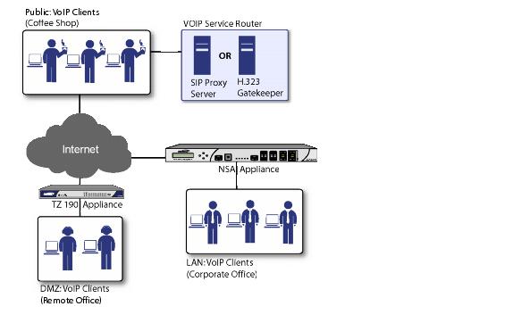
For VoIP clients that register with a server from the WAN, the SonicWALL security appliance
automatically manages NAT policies and access rules. The SonicWALL security appliance performs stateful monitoring of registration and permits incoming calls for clients while they remain registered. No configuration of clients is required. See the ““Using the Public Server Wizard”
” section for information on configuring this deployment.
The organization deploys its own VoIP server on a DMZ or LAN to provide in-house VoIP
services that are accessible to VoIP clients on the Internet or from local network users behind the security gateway. The following figure shows a trusted VoIP service topology.
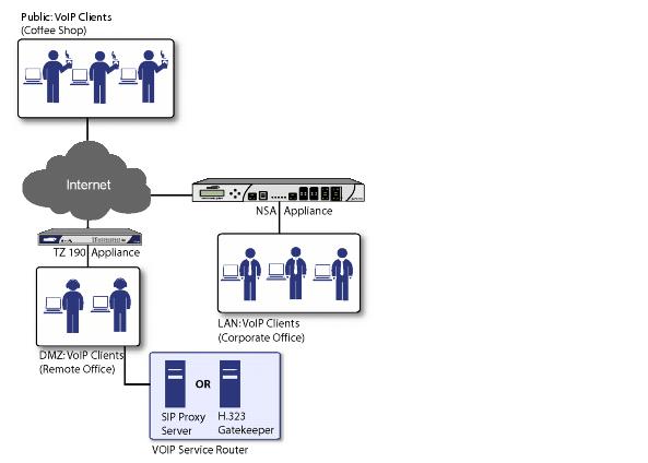
For VoIP clients that register with a server on the DMZ or LAN, the SonicWALL security
appliance automatically manages NAT policies and access rules. The SonicWALL security appliance performs stateful monitoring of registration and permits incoming calls for clients while they remain registered. No configuration on the VoIP clients is required.
To make a server on the LAN accessible to clients on the WAN:
The
VoIP > Call Status
page provides a listing of currently active VoIP calls. The VoIP Call Status table displays the following information about the active VoIP connection:
Click
Flush All
to remove all VoIP call entries.