PANEL_editInterface
The following sections describe interface configuration:
• Configuring the Static Interfaces
• Configuring Interfaces in Transparent IP Mode (Splice L3 Subnet)
• Configuring Link Aggregation and Port Redundancy
• Configuring SonicWALL PortShield Switch Mode Interfaces
• Configuring VLAN Subinterfaces
• Configuring Layer 2 Bridge Mode
• Configuring IPS Sniffer Mode
For general information on interfaces, see Network > Interfaces.
Static means that you assign a fixed IP address to the interface.
Step 1 Click on the Configure icon ![]() in the Configure column for the Interface you want to configure. The Edit Interface window is displayed.
in the Configure column for the Interface you want to configure. The Edit Interface window is displayed.
• You can configure X0 through X21.
• If you want to create a new zone, select Create new zone. The Add Zone window is displayed. See Network > Zones for instructions on adding a zone.
Step 2 Select a zone to assign to the interface. You can select LAN, WAN, DMZ, WLAN, or a custom zone.
Step 3 Select Static from the IP Assignment menu.
Step 4 Enter the IP address and subnet mask of the zone in the IP Address and Subnet Mask fields.
Note You cannot enter an IP address that is in the same subnet as another zone.
Step 5 Enter any optional comment text in the Comment field. This text is displayed in the Comment column of the Interface table.
Step 6 If you want to enable remote management of the SonicWALL SuperMassive from this interface, select the supported management protocol(s): HTTP, HTTPS, SSH, Ping, SNMP, and/or SSH.
To allow access to the WAN interface for management from another zone on the same appliance, access rules must be created. See Allowing WAN Primary IP Access from the LAN Zone for more information.
Step 7 If you want to allow selected users with limited management rights to log in to the security appliance, select HTTP and/or HTTPS in User Login.
Step 8 Click OK.
Note The administrator password is required to regenerate encryption keys after changing the SonicWALL SuperMassive’s address.
Configuring Advanced Settings for the Interface
If you need to force an Ethernet speed, duplex and/or MAC address, click the Advanced tab. The Ethernet Settings section allows you to manage the Ethernet settings of links connected to the SonicWALL. Auto Negotiate is selected by default as the Link Speed because the Ethernet links automatically negotiate the speed and duplex mode of the Ethernet connection. If you want to specify the forced Ethernet speed and duplex, select one of the following options from the Link Speed menu:
• X0 to X5 interfaces at 10 Gbps - Full Duplex
• X6 to X21 interfaces at 1 Gbps - Full Duplex
• MGMT interface 100 Mbps - Full Duplex
You can choose to override the Default MAC Address for the Interface by selecting Override Default MAC Address and entering the MAC address in the field.
Check Enable Multicast Support to allow multicast reception on this interface.
Caution If you select a specific Ethernet speed and duplex, you must force the connection speed and duplex from the Ethernet card to the SonicWALL SuperMassive as well.
Transparent IP Mode enables the SonicWALL SuperMassive to bridge the WAN subnet onto an internal interface. To configure an interface for transparent mode, complete the following steps:
Step 1 Click on the Configure icon in the Configure column for Unassigned Interface you want to configure. The Edit Interface window is displayed.
Step 2 Select an interface.
• If you select a configurable interface, select LAN or DMZ for Zone.
• If you want to create a new zone for the configurable interface, select Create a new zone. The Add Zone window is displayed. See Network > Zones for instructions on adding a zone.
Step 3 Select Transparent IP Mode (Splice L3 Subnet) from the IP Assignment menu.
Step 4 From the Transparent Range menu, select an address object that contains the range of IP addresses you want to have access through this interface. The address range must be within the WAN zone and must not include the WAN interface IP address. If you do not have an address object configured that meets your needs:
In the Transparent Range menu, select Create New Address Object.
In the Add Address Object window, enter a name for the address range.
For Zone Assignment, select WAN.
For Type, select:
• Host if you want only one network device to connect to this interface.
• Range to specify a range of IP addresses by entering beginning and ending value of the range.
• Network to specify a subnet by entering the beginning value and the subnet mask. The subnet must be within the WAN address range and cannot include the WAN interface IP address.
Enter the IP address of the host, the beginning and ending address of the range, or the IP address and subnet mask of the network.
Click OK to create the address object and return to the Edit Interface window.
See Network > Address Objects for more information.
Step 5 Enter any optional comment text in the Comment field. This text is displayed in the Comment column of the Interface table.
Step 6 If you want to enable remote management of the SonicWALL SuperMassive from this interface, select the supported management protocol(s): HTTP, HTTPS, SSH, Ping, SNMP, and/or SSH.
To allow access to the WAN interface for management from another zone on the same appliance, access rules must be created. See Allowing WAN Primary IP Access from the LAN Zone for more information.
Step 7 If you want to allow selected users with limited management rights to log directly into the security appliance through this interface, select HTTP and/or HTTPS in User Login.
Step 8 Click OK.
Note The administrator password is required to regenerate encryption keys after changing the SonicWALL SuperMassive’s address.
Configuring Advanced Settings for the Interface
If you need to force an Ethernet speed, duplex and/or MAC address, click the Advanced tab. The Ethernet Settings section allows you to manage the Ethernet settings of links connected to the SonicWALL. Auto Negotiate is selected by default as the Link Speed because the Ethernet links automatically negotiate the speed and duplex mode of the Ethernet connection. If you want to specify the forced Ethernet speed and duplex, select one of the following options from the Link Speed menu:
• X0 to X5 interfaces at 10 Gbps - Full Duplex
• X6 to X21 interfaces at 1 Gbps - Full Duplex
• MGMT interface 100 Mbps - Full Duplex
You can choose to override the Default MAC Address for the Interface by selecting Override Default MAC Address and entering the MAC address in the field.
Check Enable Multicast Support to allow multicast reception on this interface.
Caution If you select a specific Ethernet speed and duplex, you must force the connection speed and duplex from the Ethernet card to the SonicWALL SuperMassive as well.
Configuring the WAN interface enables Internet connect connectivity. You can configure up to two WAN interfaces on the SonicWALL SuperMassive.
Step 1 Click on the Edit ![]() icon in the Configure column for the Interface you want to configure. The Edit Interface window is displayed.
icon in the Configure column for the Interface you want to configure. The Edit Interface window is displayed.
Step 2 If you’re configuring an Unassigned Interface, select WAN from the Zone menu. If you selected the Default WAN Interface, WAN is already selected in the Zone menu.Select one of the following WAN Network Addressing Mode from the IP Assignment menu. Depending on the option you choose from the IP Assignment menu, complete the corresponding fields that are displayed after selecting the option.
• Static - configures the SonicWALL for a network that uses static IP addresses.
• DHCP - configures the SonicWALL to request IP settings from a DHCP server on the Internet. NAT with DHCP Client is a typical network addressing mode for cable and DSL customers.
• PPPoE - uses Point to Point Protocol over Ethernet (PPPoE) to connect to the Internet. If desktop software and a username and password is required by your ISP, select NAT with PPPoE. This protocol is typically found when using a DSL modem.
• PPTP - uses PPTP (Point to Point Tunneling Protocol) to connect to a remote server. It supports older Microsoft Windows implementations requiring tunneling connectivity.
• L2TP - uses IPsec to connect a L2TP (Layer 2 Tunneling Protocol) server and encrypts all data transmitted from the client to the server. However, it does not encrypt network traffic to other destinations.
Note For Windows clients, L2TP is supported by Windows 2000 and Windows XP. If you are running other versions of Windows, you must use PPTP as your tunneling protocol.
Step 3 If you want to enable remote management of the SonicWALL SuperMassive from this interface, select the supported management protocol(s): HTTP, HTTPS, SSH, Ping, SNMP, and/or SSH. You can also select HTTP for management traffic. However, bear in mind that HTTP traffic is less secure than HTTPS.
To allow access to the WAN interface for management from another zone on the same appliance, access rules must be created. See Allowing WAN Primary IP Access from the LAN Zone for more information.
Step 4 If you want to allow selected users with limited management rights to log directly into the security appliance from this interface, select HTTP and/or HTTPS in User Login.
Step 5 Check Add rule to enable redirect from HTTP to HTTPS, if you want an HTTP connection automatically redirected to a secure HTTPS connection to the SonicWALL SuperMassive management interface.
Step 6 After completing the WAN configuration for your Network Addressing Mode, click OK.
Configuring the Advanced Settings for the WAN Interface
The Advanced tab includes settings for forcing an Ethernet speed and duplex, overriding the Default MAC address, setting up bandwidth management, and creating a default NAT policy automatically.Ethernet Settings
If you need to force an Ethernet speed, duplex and/or MAC address, click the Advanced tab. The Ethernet Settings section allows you to manage the Ethernet settings of links connected to the SonicWALL. Auto Negotiate is selected by default as the Link Speed because the Ethernet links automatically negotiate the speed and duplex mode of the Ethernet connection. If you want to specify the forced Ethernet speed and duplex, select one of the following options from the Link Speed menu:
• X0 to X5 interfaces at 10 Gbps - Full Duplex
• X6 to X21 interfaces at 1 Gbps - Full Duplex
• MGMT interface 100 Mbps - Full Duplex
You can choose to override the Default MAC Address for the Interface by selecting Override Default MAC Address and entering the MAC address in the field.
Caution If you select a specific Ethernet speed and duplex, you must force the connection speed and duplex from the Ethernet card to the SonicWALL as well.
Check Enable Multicast Support to allow multicast reception on this interface.
On SonicWALL SuperMassives, check Enable 802.1p tagging to tag information passing through this interface with 802.1p priority information for Quality of Service (QoS) management. Packets sent through this interface are tagged with VLAN id=0 and carry 802.1p priority information. In order to make use of this priority information, devices connected to this interface should support priority frames. QoS management is controlled by access rules on the Firewall > Access Rules page. For information on QoS and bandwidth management, see Firewall Settings > QoS Mapping.
You can also specify any of these additional Ethernet Settings:
• Interface MTU - Specifies the largest packet size that the interface can forward without fragmenting the packet.
• Fragment non-VPN outbound packets larger than this Interface’s MTU - Specifies all non-VPN outbound packets larger than this Interface’s MTU be fragmented. Specifying the fragmenting of VPN outbound packets is set in the VPN > Advanced page.
• Ignore Don’t Fragment (DF) Bit - Overrides DF bits in packets.
• Do not send ICMP Fragmentation Needed for outbound packets over the Interface MTU - blocks notification that this interface can receive fragmented packets.
Bandwidth Management
SonicOS can apply bandwidth management to both egress (outbound) and ingress (inbound) traffic on the interfaces in the WAN zone. Outbound bandwidth management is done using Class Based Queuing. Inbound Bandwidth Management is done by implementing ACK delay algorithm that uses TCP’s intrinsic behavior to control the traffic.
Class Based Queuing (CBQ) provides guaranteed and maximum bandwidth Quality of Service (QoS) for the SonicWALL SuperMassive. Every packet destined to the WAN interface is queued in the corresponding priority queue. The scheduler then dequeues the packets and transmits it on the link depending on the guaranteed bandwidth for the flow and the available link bandwidth.
Note Use the Bandwidth Management section of the Edit Interface screen to enable or disable the ingress and egress bandwidth management. Egress and Ingress available link bandwidth can be used to configure the upstream and downstream connection speeds in kilobits per second.The Bandwidth Management settings are applied to all interfaces in the WAN zone, not just to the interface being configured.
• Enable Egress Bandwidth Management - Enables outbound bandwidth management.
– Available Interface Egress Bandwidth (Kbps) - Specifies the available bandwidth for WAN interfaces in Kbps.
• Enable Ingress Bandwidth Management - Enables inbound bandwidth management.
– Available Interface Ingress Bandwidth (Kbps) - Specifies the available bandwidth for WAN interfaces in Kbps.
Both Link Aggregation and Port Redundancy are configured on the Advanced tab of the Edit Interface window in the SonicOS UI.
• Link Aggregation - Groups multiple Ethernet interfaces together forming a single logical link to support greater throughput than a single physical interface could support. This provides the ability to send multi-gigabit traffic between two Ethernet domains.
• Port Redundancy - Configures a single redundant port for any physical interface that can be connected to a second switch to prevent a loss of connectivity in the event that either the primary interface or primary switch fail.
Link Aggregation is used to increase the available bandwidth between the firewall and a switch by aggregating up to four interfaces into a single aggregate link, referred to as a Link Aggregation Group (LAG). All ports in an aggregate link must be connected to the same switch. The firewall uses a round-robin algorithm for load balancing traffic across the interfaces in a Link Aggregation Group. Link Aggregation also provides a measure of redundancy, in that if one interface in the LAG goes down, the other interfaces remain connected.
Link Aggregation is referred to using different terminology by different vendors, including Port Channel, Ether Channel, Trunk, and Port Grouping.
Link Aggregation failover
SonicWALL provides multiple methods for protecting against loss of connectivity in the case of a link failure, including High Availability (HA), Load Balancing Groups (LB Groups), and now Link Aggregation. If all three of these features are configured on a firewall, the following order of precedence is followed in the case of a link failure:
1. High Availability
2. Link Aggregation
3. Load Balancing Groups
HA takes precedence over Link Aggregation. Because each link in the LAG carries an equal share of the load, the loss of a link on the Active firewall will force a failover to the Idle firewall (if all of its links remain connected). Physical monitoring needs to be configured only on the primary aggregate port.
When Link Aggregation is used with a LB Group, Link Aggregation takes precedence. LB will take over only if all the ports in the aggregate link are down.
Link Aggregation Limitations
• Currently only static addressing is supported for Link Aggregation
• The Link Aggregation Control Protocol (LACP) is currently not supported
Link Aggregation Configuration
To configure Link Aggregation, perform the following tasks:
1. On the Network > Interfaces page, click the configure icon for the interface that is to be designated the master of the Link Aggregation Group. The Edit Interface window displays.
2. Click on the Advanced tab.In the Redundant/Aggregate Ports pull-down menu, select Link Aggregation.
3. The Aggregate Port option is displayed with a checkbox for each of the currently unassigned interfaces on the firewall. Select up to three other interfaces to assign to the LAG.
Note After an interface is assigned to a Link Aggregation Group, its configuration is governed by the Link Aggregation master interface and it cannot be configured independently. In the Interface Settings table, the interface's zone is displayed as "Aggregate Port" and the configuration icon is removed.
4. Set the Link Speed for the interface to Auto-Negotiate.
5. Click OK.
Note Link Aggregation requires a matching configuration on the Switch. The switch's method of load balancing will very depending on the vendor. Consult the documentation for the switch for information on configuring Link Aggregation. Remember that it may be referred to as Port Channel, Ether Channel, Trunk, or Port Grouping.
Port Redundancy provides a simple method for configuring a redundant port for a physical Ethernet port. This is a valuable feature, particularly in high-end deployments, to protect against switch failures being a single point of failure.
When the primary interface is active, it processes all traffic to and from the interface. If the primary interface goes down, the secondary interface takes over all outgoing and incoming traffic. The secondary interface assumes the MAC address of the primary interface and sends the appropriate gratuitous ARP on a failover event. When the primary interface comes up again, it resumes responsibility for all traffic handling duties from the secondary interface.
In a typical Port Redundancy configuration, the primary and secondary interfaces are connected to different switches. This provides for a failover path in case the primary switch goes down. Both switches must be on the same Ethernet domain. Port Redundancy can also be configured with both interfaces connected to the same switch.
Port Redundancy Failover
SonicWALL provides multiple methods for protecting against loss of connectivity in the case of a link failure, including High Availability (HA), Load Balancing Groups (LB Groups), and now Port Redundancy. If all three of these features are configured on a firewall, the following order of precedence is followed in the case of a link failure:
1. Port Redundancy
2. HA
3. LB Group
When Port Redundancy is used with HA, Port Redundancy takes precedence. Typically an interface failover will cause an HA failover to occur, but if a redundant port is available for that interface, then an interface failover will occur but not an HA failover. If both the primary and secondary redundant ports go down, then an HA failover will occur (assuming the secondary firewall has the corresponding port active).
When Port Redundancy is used with a LB Group, Port Redundancy again takes precedence. Any single port (primary or secondary) failures are handled by Port Redundancy just like with HA. When both the ports are down then LB kicks in and tries to find an alternate interface.
Port Redundancy Configuration
To configure Port Redundancy, perform the following tasks:
1. On the Network > Interfaces page, click the configure icon for the interface that is to be designated the master of the Link Aggregation Group. The Edit Interface window displays.
2. Click on the Advanced tab.In the Redundant/Aggregate Ports pull-down menu, select Port Redundancy.
3. The Redundant Port pull-down menu is displayed, with all of the currently unassigned interfaces available. Select one of the interfaces.
Note After an interface is selected as a Redundant Port, its configuration is governed by the primary interface and it can not be configured independently. In the Interface Settings table, the interface's zone is displayed as "Redundant Port" and the configuration icon is removed.
4. Set the Link Speed for the interface to Auto-Negotiate.
5. Click OK.
Routed Mode provides an alternative for NAT for routing traffic between separate public IP address ranges. Consider the following topology where the firewall is routing traffic across two public IP address ranges:
• 10.50.26.0/24
• 172.16.6.0/24
By enabling Routed Mode on the interface for the 172.16.6.0 network, NAT translations will be automatically disabled for the interface, and all inbound and outbound traffic will be routed to the WAN interface configured for the 10.50.26.0 network.
To configure Routed Mode, perform the following steps:
1. Navigate to the Network > Interfaces page. Click on the configure icon for the appropriate interface. The Edit Interface window displays.
2. Click on the Advanced tab.Under the Expert Mode Settings heading, select the Use Routed Mode - Add NAT Policy to prevent outbound\inbound translation checkbox to enable Routed Mode for the interface.
3. In the Set NAT Policy's outbound\inbound interface to pull-down menu, select the WAN interface that is to be used to route traffic for the interface.
4. Click OK.
The firewall then creates “no-NAT” policies for both the configured interface and the selected WAN interface. These policies override any more general M21 NAT policies that may be configured for the interfaces.
PortShield architecture enables you to configure some or all of the LAN ports into separate security contexts, providing protection not only from the WAN and DMZ, but between devices inside your network as well. In effect, each context has its own wire-speed PortShield that enjoys the protection of a dedicated, deep packet inspection firewall.
Tip Zones can always be applied to multiple interfaces in the Network > Interfaces page, even without the use of PortShield groupings. However, these interfaces will not share the same network subnet unless they are grouped using PortShield.
You can assign any combination of ports into a PortShield interface. All ports you do not assign to a PortShield interface are assigned to the LAN interface.
To configure a PortShield interface, perform the following steps:
Step 1 Click on the Network > Interfaces page.
Step 2 Click the Configure button for the interface you want to configure. The Edit Interface window displays.In the Zone pull-down menu, select on a zone type option to which you want to map the interface.
Note You can add PortShield interfaces only to Trusted, Public, and Wireless zones.
Step 3 In the IP Assignment pull-down menu, select PortShield Switch Mode.
Step 4 In the PortShield to pull-down menu, select the interface you want to map this port to. Only ports that match the zone you have selected are displayed.
When you add a VLAN subinterface, you need to assign it to a zone, assign it a VLAN Tag, and assign it to a physical interface. Based on your zone assignment, you configure the VLAN subinterface the same way you configure a physical interface for the same zone.
Adding a virtual interface
Step 1 In the left-navigation menu click on Network and then Interfaces to display the Network > Interfaces page.
Step 2 At the bottom of the Interface Settings table, click Add Interface. The Edit Interface window displays.
Step 3 Select a zone to assign to the interface. You can select LAN, WAN, DMZ, WLAN, or a custom zone. The zone assignment does not have to be the same as the parent (physical) interface. In fact, the parent interface can even remain Unassigned.
Your configuration choices for the network settings of the subinterface depend on the zone you select.
• LAN, DMZ, or a custom zone of Trusted type: Static or Transparent
• WLAN or a custom Wireless zone: static IP only (no IP Assignment list).
Step 4 Assign a VLAN tag (ID) to the subinterface. Valid VLAN ID’s are 1 to 4095, although some switches reserve VLAN 1 for native VLAN designation. You will need to create a VLAN subinterface with a corresponding VLAN ID for each VLAN you wish to secure with your security appliance.
Step 5 Declare the parent (physical) interface to which this subinterface will belong. There is no per-interface limit to the number of subinterfaces you can assign – you may assign subinterfaces up to the system limit.
Step 6 Configure the subinterface network settings based on the zone you selected. See the interface configuration instructions earlier in this chapter:
– Configuring the Static Interfaces
– Configuring Advanced Settings for the Interface
– Configuring Interfaces in Transparent IP Mode (Splice L3 Subnet)
– Configuring SonicWALL PortShield Switch Mode Interfaces
– Configuring VLAN Subinterfaces
Step 7 Select the management and user-login methods for the subinterface.
Step 8 Click OK.
To configure the SonicWALL SuperMassive for IPS Sniffer Mode, you will use two interfaces in the same zone for the L2 Bridge-Pair. You can use any interfaces except the WAN interface. For this example, we will use X2 and X3 for the Bridge-Pair, and configure them to be in the LAN zone. The WAN interface (X1) is used by the SonicWALL appliance for access to the SonicWALL Data Center as needed. The mirrored port on the switch will connect to one of the interfaces in the Bridge-Pair.
This section contains the following topics:
• Configuration Task List for IPS Sniffer Mode
• Configuring the Primary Bridge Interface
• Configuring the Secondary Bridge Interface
• Enabling and Configuring SNMP
• Configuring Security Services (Unified Threat Management)
• Connecting the Mirrored Switch Port to a IPS Sniffer Mode Interface
• Connecting and Configuring the WAN Interface to the Data Center
• Configure the Primary Bridge Interface
– Select LAN as the Zone for the Primary Bridge Interface
– Assign a static IP address
• Configure the Secondary Bridge Interface
– Select LAN as the Zone for the Secondary Bridge Interface
– Enable the L2 Bridge to the Primary Bridge interface
• Enable SNMP and configure the IP address of the SNMP manager system where traps can be sent
• Configure Security Services (UTM) for LAN traffic
• Configure logging alert settings to “Alert” or below
• Connect the mirrored port on the switch to either one of the interfaces in the Bridge-Pair
• Connect and configure the WAN to allow access to dynamic signature data over the Internet
Step 1 Select the Network tab, Interfaces folder from the navigation panel.
Step 2 Click the Configure icon in the right column of interface X2.
Step 3 In the Edit Interface dialog box on the General tab, select LAN from the Zone drop-down list.
Note that you do not need to configure settings on the Advanced or VLAN Filtering tabs.
Step 4 For IP Assignment, select Static from the drop-down list.
Step 5 Configure the interface with a static IP Address (e.g. 10.1.2.3). The IP address you choose should not collide with any of the networks that are seen by the switch.
Note The Primary Bridge Interface must have a static IP assignment.
Step 6 Configure the Subnet Mask.
Step 7 Type in a descriptive comment.
Step 8 Select management options for the interface (HTTP, HTTPS, Ping, SNMP, SSH, User Logins, HTTP Redirects).
Step 9 Click OK.
Our example continues with X3 as the secondary bridge interface.
Step 1 Select the Network tab, Interfaces folder from the navigation panel.
Step 2 Click the Configure icon in the right column of the X3 interface.
Step 3 In the Edit Interface dialog box on the General tab, select LAN from the Zone drop-down list.
Note that you do not need to configure settings on the Advanced or VLAN Filtering tabs.
Step 4 In the IP Assignment drop-down list, select Layer 2 Bridged Mode.
Step 5 In the Bridged to drop-down list, select the X2 interface.
Step 6 Do not enable the Block all non-IPv4 traffic setting if you want to monitor non-IPv4 traffic.
Step 7 Select Never route traffic on this bridge-pair to ensure that the traffic from the mirrored switch port is not sent back out onto the network.
Step 8 Select Only sniff traffic on this bridge-pair to enable sniffing or monitoring of packets that arrive on the L2 Bridge from the mirrored switch port.
Step 9 Select Disable stateful-inspection on this bridge-pair to exempt these interfaces from stateful high availability inspection. If Deep Packet Inspection services are enabled for these interfaces, the DPI services will continue to be applied.
Step 10 Configure management (HTTP, HTTPS, Ping, SNMP, SSH, User Logins, HTTP Redirects).
Step 11 Click OK.
When SNMP is enabled, SNMP traps are automatically triggered for many events that are generated by SonicWALL Security Services such as Intrusion Prevention and Gateway Anti-Virus.
More than 50 IPS and GAV events currently trigger SNMP traps. The SonicOS Log Event Reference Guide contains a list of events that are logged by SonicOS, and includes the SNMP trap number where applicable. The guide is available online at
http://www.sonicwall.com/us/Support.html by typing Log Event into the Search field at the top of the page.
To determine the traps that are possible when using IPS Sniffer Mode with Intrusion Prevention enabled, search for Intrusion in the table found in the Index of Log Event Messages section in the SonicOS Log Event Reference Guide. The SNMP trap number, if available for that event, is printed in the SNMP Trap Type column of the table.
To determine the possible traps with Gateway Anti-Virus enabled, search the table for Security Services, and view the SNMP trap number in the SNMP Trap Type column.
To enable and configure SNMP:
Step 1 Select the System tab, Administration folder from the navigation panel.
Step 2 Scroll down to the Advanced Management section.
Step 3 Select the Enable SNMP checkbox. The Configure button becomes active.
Step 4 Click Configure. The SNMP Settings dialog box is displayed.
Step 5 In the SNMP Settings dialog box, for System Name, type the name of the SNMP manager system that will receive the traps sent from the SonicWALL.
Step 6 Enter the name or email address of the contact person for the SNMP Contact
Step 7 Enter a description of the system location, such as “3rd floor lab”.
Step 8 Enter the system’s asset number.
Step 9 For Get Community Name, type the community name that has permissions to retrieve SNMP information from the SonicWALL, e.g. public.
Step 10 For Trap Community Name, type the community name that will be used to send SNMP traps from the SonicWALL to the SNMP manager, e.g. public.
Step 11 For the Host fields, type in the IP address(es) of the SNMP manager system(s) that will receive the traps.
Step 12 Click OK.
The settings that you enable in this section will control what type of malicious traffic you detect in IPS Sniffer Mode. Typically you will want to enable Intrusion Prevention, but you may also want to enable other Security Services such as Gateway Anti-Virus or Anti-Spyware.
To enable Security Services, your SonicWALL must be licensed for them and the signatures must be downloaded from the SonicWALL Data Center. For complete instructions on enabling and configuring IPS, GAV, and Anti-Spyware, see the Security Services section in this guide.
You can configure logging to record entries for attacks that are detected by the SonicWALL.
To enable logging, perform the following steps:
Step 1 Select the Log tab, Categories folder from the navigation panel.
Step 2 Under Log Categories, select All Categories in the View Style drop-down list.
Step 3 In the Attacks category, enable the checkboxes for Log, Alerts, and Syslog.
Step 4 Click Apply.
Use a standard Cat-5 Ethernet cable to connect the mirrored switch port to either interface in the Bridge-Pair. Network traffic will automatically be sent from the switch to the SonicWALL where it can be inspected.
Consult the switch documentation for instructions on setting up the mirrored port.
Connect the WAN port on the SonicWALL, typically port X1, to your gateway or to a device with access to the gateway. The SonicWALL communicates with the SonicWALL Data Center automatically. For detailed instructions on configuring the WAN interface, see Configuring a WAN Interface.
SonicOS 6.0 introduces Wire Mode and Tap Mode, which provide new methods non-disruptive, incremental insertion into networks.
|
To summarize the key functional differences between modes of interface configuration:
|
|
Note When operating in Wire-Mode, the SuperMassive’s dedicated “Management” interface will be used for local management. To enable remote management and dynamic security services and application intelligence updates, a WAN interface (separate from the Wire-Mode interfaces) must be configured for Internet connectivity. This is easily done given that SonicOS supports interfaces in mixed-modes of almost any combination.
To configure an interface for Wire Mode, perform the following steps:
1. On the Network > Interfaces page, click the Configure button for the interface you want to configure for Wire Mode.
2. In the Zone pull-down menu, select LAN.
3. To configure the Interface for Tap Mode, in the Mode / IP Assignment pull-down menu, select Tap Mode (1-Port Tap).
4. To configure the Interface for Wire Mode, in the Mode / IP Assignment pull-down menu, select Wire Mode (2-Port Wire).
5. In the Wire Mode Type pull-down menu, select the appropriate mode:
– Bypass (via Internal Switch/Relay)
– Inspect (Passive DPI of Mirrored Traffic)
– Secure (Active DPI of Inline Traffic)
6. In the Paired Interface pull-down menu, select the interface that will connect to the upstream firewall. The paired interfaces must be of the same type (two 1 GB interfaces or two 10 GB interfaces).
Note Only unassigned interfaces are available in the Paired Interface pull-down menu. To make an interface unassigned, click on the Configure button for it, and in the Zone pull-down menu, select Unassigned.
7. When the interface configured for Secure Wire Mode, the Bypass when SonicOS is restarting or down option is configurable. Because the SonicWALL SuperMassive appliance is a true switch architecture, traffic can continuously be passed, even when SonicOS is restarting or down. This traffic will not have DPI services applied to it until SonicOS fully restarts. This option is enabled by default when configuring Secure Mode. Uncheck the Bypass when SonicOS is restarting or down checkbox to disable traffic flow while the appliance is restarting.
8. Click OK.
SonicOS includes L2 (Layer 2) Bridge Mode, a new method of unobtrusively integrating a SonicWALL SuperMassive into any Ethernet network. L2 Bridge Mode is ostensibly similar to SonicOS’s Transparent Mode in that it enables a SonicWALL SuperMassive to share a common subnet across two interfaces, and to perform stateful and deep-packet inspection on all traversing IP traffic, but it is functionally more versatile.
In particular, L2 Bridge Mode employs a secure learning bridge architecture, enabling it to pass and inspect traffic types that cannot be handled by many other methods of transparent security appliance integration. Using L2 Bridge Mode, a SonicWALL SuperMassive can be non-disruptively added to any Ethernet network to provide in-line deep-packet inspection for all traversing IPv4 TCP and UDP traffic. In this scenario the SonicWALL SuperMassive is not used for security enforcement, but instead for bidirectional scanning, blocking viruses and spyware, and stopping intrusion attempts.
Unlike other transparent solutions, L2 Bridge Mode can pass all traffic types, including IEEE 802.1Q VLANs, Spanning Tree Protocol, multicast, broadcast, and IPv6, ensuring that all network communications will continue uninterrupted.
Another aspect of the versatility of L2 Bridge Mode is that you can use it to configure IPS Sniffer Mode. Supported on SonicWALL SuperMassives, IPS Sniffer Mode uses a single interface of a Bridge-Pair to monitor network traffic from a mirrored port on a switch. IPS Sniffer Mode provides intrusion detection, but cannot block malicious traffic because the SonicWALL SuperMassive is not connected inline with the traffic flow. For more information about IPS Sniffer Mode, see IPS Sniffer Mode .
L2 Bridge Mode provides an ideal solution for networks that already have an existing firewall, and do not have immediate plans to replace their existing firewall but wish to add the security of SonicWALL Unified Threat Management (UTM) deep-packet inspection, such as Intrusion Prevention Services, Gateway Anti Virus, and Gateway Anti Spyware. If you do not have SonicWALL UTM security services subscriptions, you may sign up for free trials from the Security Service > Summary page of your SonicWALL.
You can also use L2 Bridge Mode in a High Availability deployment. This scenario is explained in the Layer 2 Bridge Mode with High Availability.
See the following sections:
• Key Features of SonicOS Layer 2 Bridge Mode
• Key Concepts to Configuring L2 Bridge Mode and Transparent Mode
• Comparing L2 Bridge Mode to Transparent Mode
• L2 Bridge Path Determination
• L2 Bridge Interface Zone Selection
The following table outlines the benefits of each key feature of layer 2 bridge mode:
|
The following terms will be used when referring to the operation and configuration of L2 Bridge Mode:
• L2 Bridge Mode – A method of configuring SonicWALL SuperMassive, which enables the SonicWALL to be inserted inline into an existing network with absolute transparency, beyond even that provided by Transparent Mode. Layer 2 Bridge Mode also refers to the IP Assignment configuration that is selected for Secondary Bridge Interfaces that are placed into a Bridge-Pair.
• Transparent Mode – A method of configuring a SonicWALL SuperMassive that allows the SonicWALL to be inserted into an existing network without the need for IP reconfiguration by spanning a single IP subnet across two or more interfaces through the use of automatically applied ARP and routing logic.
• IP Assignment – When configuring a Trusted (LAN) or Public (DMZ) interface, the IP Assignment for the interface can either be:
– Static – The IP address for the interface is manually entered.
– Transparent Mode – The IP address(es) for the interface is assigned using an Address Object (Host, Range, or Group) that falls within the WAN Primary IP subnet, effectively spanning the subnet from the WAN interface to the assigned interface.
– Layer 2 Bridge Mode – An interface placed in this mode becomes the Secondary Bridge Interface to the Primary Bridge Interface to which it is paired. The resulting Bridge-Pair will then behave like a two-port learning bridge with full L2 transparency, and all IP traffic that passes through will be subjected to full stateful failover and deep packet inspection.
• Bridge-Pair – The logical interface set composed of a Primary Bridge Interface and a Secondary Bridge Interface. The terms primary and secondary do not imply any inherent level of operational dominance or subordination; both interfaces continue to be treated according to their zone type, and to pass IP traffic according to their configured Access Rules. Non-IPv4 traffic across the Bridge-Pair is controlled by the Block all non-IPv4 traffic setting on the Secondary Bridge Interface. A system may support as many Bridge Pairs as it has interface pairs available. In other words, the maximum number of Bridge-Pairs is equal to ½ the number of physical interfaces on the platform. Membership in a Bridge-Pair does not preclude an interface from conventional behavior; for example, if X1 is configured as a Primary Bridge Interface paired to X3 as a Secondary Bridge Interface, X1 can simultaneously operate in its traditional role as the Primary WAN, performing NAT for Internet-bound traffic through the Auto-added X1 Default NAT Policy.
• Primary Bridge Interface – A designation that is assigned to an interface once a Secondary Bridge Interface has been paired to it. A Primary Bridge Interface can belong to an Untrusted (WAN), Trusted (LAN), or Public (DMZ) zone.
• Secondary Bridge Interface – A designation that is assigned to an interface whose IP Assignment has been configured for Layer 2 Bridge Mode. A Secondary Bridge Interface can belong to a Trusted (LAN), or Public (DMZ) zone.
• Bridge Management Address – The address of the Primary Bridge Interface is shared by both interfaces of the Bridge-Pair. If the Primary Bridge Interface also happens to be the Primary WAN interface, it is this address that is uses for outbound communications by the SonicWALL, such as NTP, and License Manager updates. Hosts that are connected to either segment of the Bridge-Pair may also use the Bridge Management Address as their gateway, as will be common in Mixed-Mode deployments.
• Bridge-Partner – The term used to refer to the ‘other’ member of a Bridge-Pair.
• Non-IPv4 Traffic - SonicOS supports the following IP protocol types: ICMP (1), IGMP (2), TCP (6), UDP (17), GRE (47), ESP (50), AH (51), EIGRP (88), OSPF (89), PIM-SM (103), L2TP (115). More esoteric IP types, such as Combat Radio Transport Protocol (126), are not natively handled by the SonicWALL, nor are non-IPv4 traffic types such as IPX or (currently) IPv6. L2 Bridge Mode can be configured to either pass or drop Non-IPv4 traffic.
• Captive-Bridge Mode – This optional mode of L2 Bridge operation prevents traffic that has entered an L2 bridge from being forwarded to a non-Bridge-Pair interface. By default, L2 Bridge logic will forward traffic that has entered the L2 Bridge to its destination along the most optimal path as determined by ARP and routing tables. In some cases, the most optimal path might involve routing or NATing to a non-Bridge-Pair interface. Activating Captive-Bridge mode ensures that traffic which enters an L2 Bridge exits the L2 Bridge rather than taking its most logically optimal path. In general, this mode of operation is only required in complex networks with redundant paths, where strict path adherence is required.
• Pure L2 Bridge Topology – Refers to deployments where the SonicWALL will be used strictly in L2 Bridge Mode for the purposes of providing in-line security to a network. This means that all traffic entering one side of the Bridge-Pair will be bound for the other side, and will not be routed/NATed through a different interface. This will be common in cases where there is an existing perimeter security appliance, or where in-line security is desired along some path (for example, inter-departmentally, or on a trunked link between two switches) of an existing network. Pure L2 Bridge Topology is not a functional limitation, but rather a topological description of a common deployment in heterogeneous environments.
• Mixed-Mode Topology – Refers to deployments where the Bridge-Pair will not will not be the only point of ingress/egress through the SonicWALL. This means that traffic entering one side of the Bridge-Pair may be destined to be routed/NATed through a different interface. This will be common when the SonicWALL is simultaneously used to provide security to one or more Bridge-Pair while also providing:
– Perimeter security, such as WAN connectivity, to hosts on the Bridge-Pair or on other interfaces.
– Firewall and Security services to additional segments, such as Trusted (LAN) or Public (DMZ) interface, where communications will occur between hosts on those segments and hosts on the Bridge-Pair.
This comparison of L2 Bridge Mode to Transparent Mode contains the following sections:
• VLAN Support in Transparent Mode
• Multiple Subnets in Transparent Mode
• Non-IPv4 Traffic in Transparent Mode
• VLAN Support in L2 Bridge Mode
• Multiple Subnets in L2 Bridge Mode
• Non-IPv4 Traffic in L2 Bridge Mode
• Comparison of L2 Bridge Mode to Transparent Mode
• Benefits of Transparent Mode over L2 Bridge Mode
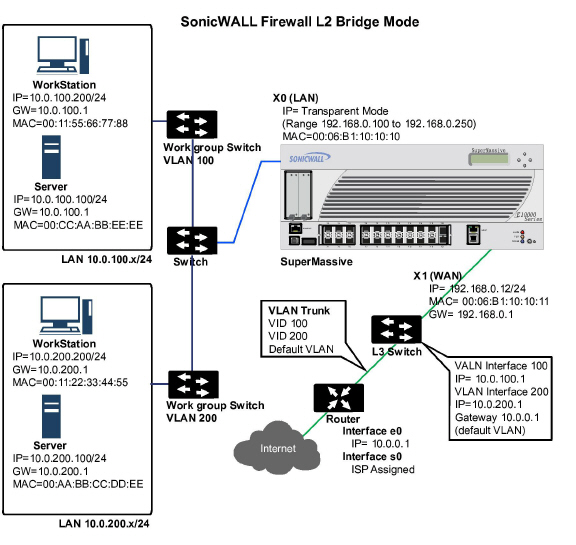
While Transparent Mode allows a security appliance running SonicOS to be introduced into an existing network without the need for re-addressing, it presents a certain level of disruptiveness, particularly with regard to ARP, VLAN support, multiple subnets, and non-IPv4 traffic types. Consider the diagram below, in a scenario where a Transparent Mode SonicWALL appliance has just been added to the network with a goal of minimally disruptive integration, particularly:
• Negligible or no unscheduled downtime
• No need to re-address any portion of the network
• No need reconfigure or otherwise modify the gateway router (as is common when the router is owned by the ISP)
ARP – Address Resolution Protocol (the mechanism by which unique hardware addresses on network interface cards are associated to IP addresses) is proxied in Transparent Mode. If the Workstation on Server on the left had previously resolved the Router (192.168.0.1) to its MAC address 00:99:10:10:10:10, this cached ARP entry would have to be cleared before these hosts could communicate through the SonicWALL. This is because the SonicWALL proxies (or answers on behalf of) the gateway’s IP (192.168.0.1) for hosts connected to interfaces operating in Transparent Mode. So when the Workstation at the left attempts to resolve 192.168.0.1, the ARP request it sends is responded to by the SonicWALL with its own X0 MAC address (00:06:B1:10:10:10).
The SonicWALL also proxy ARPs the IP addresses specified in the Transparent Range (192.168.0.100 to 192.168.0.250) assigned to an interface in Transparent Mode for ARP requests received on the X1 (Primary WAN) interface. If the Router had previously resolved the Server (192.168.0.100) to its MAC address 00:AA:BB:CC:DD:EE, this cached ARP entry would have to be cleared before the router could communicate with the host through the SonicWALL. This typically requires a flushing of the router’s ARP cache either from its management interface or through a reboot. Once the router’s ARP cache is cleared, it can then send a new ARP request for 192.168.0.100, to which the SonicWALL will respond with its X1 MAC 00:06:B1:10:10:11.
VLAN Support in Transparent Mode
While the network depicted in the above diagram is simple, it is not uncommon for larger networks to use VLANs for segmentation of traffic. If this was such a network, where the link between the switch and the router was a VLAN trunk, a Transparent Mode SonicWALL would have been able to terminate the VLANs to subinterfaces on either side of the link, but it would have required unique addressing; that is, non-Transparent Mode operation requiring re-addressing on at least one side. This is because only the Primary WAN interface can be used as the source for Transparent Mode address space.
Multiple Subnets in Transparent Mode
It is also common for larger networks to employ multiple subnets, be they on a single wire, on separate VLANs, multiple wires, or some combination. While Transparent Mode is capable of supporting multiple subnets through the use of Static ARP and Route entries, as the Technote
http://www.sonicwall.com/us/support/2134_3468.html describes, it is not an effortless process.
Non-IPv4 Traffic in Transparent Mode
Transparent Mode will drop (and generally log) all non-IPv4 traffic, precluding it from passing other traffic types, such as IPX, or unhandled IP types.
L2 Bridge Mode addresses these common Transparent Mode deployment issues and is described in the following section.
L2 Bridge Mode employs a learning bridge design where it will dynamically determine which hosts are on which interface of an L2 Bridge (referred to as a Bridge-Pair). ARP is passed through natively, meaning that a host communicating across an L2 Bridge will see the actual host MAC addresses of their peers. For example, the Workstation communicating with the Router (192.168.0.1) will see the router as 00:99:10:10:10:10, and the Router will see the Workstation (192.168.0.100) as 00:AA:BB:CC:DD:EE.
This behavior allows for a SonicWALL operating in L2 Bridge Mode to be introduced into an existing network with no disruption to most network communications other than that caused by the momentary discontinuity of the physical insertion.
Please note that stream-based TCP protocols communications (for example, an FTP session between a client and a server) will need to be re-established upon the insertion of an L2 Bridge Mode SonicWALL. This is by design so as to maintain the security afforded by stateful packet inspection (SPI); since the SPI engine can not have knowledge of the TCP connections which pre-existed it, it will drop these established packets with a log event such as TCP packet received on non-existent/closed connection; TCP packet dropped.
VLAN Support in L2 Bridge Mode
On SonicWALL SuperMassives, L2 Bridge Mode provides fine control over 802.1Q VLAN traffic traversing an L2 Bridge. The default handling of VLANs is to allow and preserve all 802.1Q VLAN tags as they pass through an L2 Bridge, while still applying all firewall rules, and stateful and deep-packet inspection to the encapsulated traffic. It is further possible to specify white/black lists for allowed/disallowed VLAN IDs through the L2 Bridge.
This allows a SonicWALL operating in L2 Bridge Mode to be inserted, for example, inline into a VLAN trunk carrying any number of VLANs, and to provide full security services to all IPv4 traffic traversing the VLAN without the need for explicit configuration of any of the VLAN IDs or subnets. Firewall Access Rules can also, optionally, be applied to all VLAN traffic passing through the L2 Bridge Mode because of the method of handling VLAN traffic.
The following sequence of events describes the above flow diagram:
1. 802.1Q encapsulated frame enters an L2 Bridge interface (this first step, the next step, and the final step apply only to 802.1Q VLAN traffic, supported on SonicWALL SuperMassives).
2. The 802.1Q VLAN ID is checked against the VLAN ID white/black list:
– If the VLAN ID is disallowed, the packet is dropped and logged.
– If the VLAN ID is allowed, the packet is de-capsulated, the VLAN ID is stored, and the inner packet (including the IP header) is passed through the full packet handler.
3. Since any number of subnets is supported by L2 Bridging, no source IP spoof checking is performed on the source IP of the packet. It is possible to configure L2 Bridges to only support a certain subnet or subnets using Firewall Access Rules.
4. SYN Flood checking is performed.
5. A destination route lookup is performed to the destination zone, so that the appropriate Firewall Access rule can be applied. Any zone is a valid destination, including the same zone as the source zone (e.g. LAN to LAN), the Untrusted zone (WAN), the Encrypted (VPN), Wireless (WLAN), Multicast, or custom zones of any type.
6. A NAT lookup is performed and applied, as needed.
– In general, the destination for packets entering an L2 Bridge will be the Bridge-Partner interface (that is, the other side of the bridge). In these cases, no translation will be performed.
– In cases where the L2 Bridge Management Address is the gateway, as will sometimes be the case in Mixed-Mode topologies, then NAT will be applied as need (see the L2 Bridge Path Determination section for more details).
7. Firewall Access Rules are applied to the packet. For example, on SonicWALL SuperMassives, the following packet decode shows an ICMP packet bearing VLAN ID 10, source IP address 110.110.110.110 destined for IP address 4.2.2.1.
It is possible to construct a Firewall Access Rule to control any IP packet, independent of its VLAN membership, by any of its IP elements, such as source IP, destination IP, or service type. If the packet is disallowed, it will be dropped and logged. If the packet is allowed, it will continue.
8. A connection cache entry is made for the packet, and required NAT translations (if any) are performed.
9. Stateful packet inspection and transformations are performed for TCP, VoIP, FTP, MSN, Oracle, RTSP and other media streams, PPTP and L2TP. If the packet is disallowed, it will be dropped and logged. If the packet is allowed, it will continue.
10.Deep packet inspection, including GAV, IPS, Anti-Spyware, CFS and email-filtering is performed. If the packet is disallowed, it will be dropped and logged. If the packet is allowed, it will continue. Client notification will be performed as configured.
11.If the packet is destined for the Encrypted zone (VPN), the Untrusted zone (WAN), or some other connected interface (the last two of which might be the case in Mixed-Mode Topologies) the packet will be sent via the appropriate path.
12.If the packet is not destined for the VPN/WAN/Connected interface, the stored VLAN tag will be restored, and the packet (again bearing the original VLAN tag) will be sent out the Bridge-Partner interface.
Multiple Subnets in L2 Bridge Mode
L2 Bridge Mode is capable of handling any number of subnets across the bridge, as described above. The default behavior is to allow all subnets, but Access Rules can be applied to control traffic as needed.
Non-IPv4 Traffic in L2 Bridge Mode
Unsupported traffic will, by default, be passed from one L2 Bridge interface to the Bridge-Partner interface. This allows the SonicWALL to pass other traffic types, including LLC packets such as Spanning Tree, other EtherTypes, such as MPLS label switched packets (EtherType 0x8847), Appletalk (EtherType 0x809b), and the ever-popular Banyan Vines (EtherType 0xbad). These non-IPv4 packets will only be passed across the Bridge, they will not be inspected or controlled by the packet handler. If these traffic types are not needed or desired, the bridging behavior can be changed by enabling the Block all non-IPv4 traffic option on the Secondary Bridge Interface configuration page.
Comparison of L2 Bridge Mode to Transparent Mode
|
Benefits of Transparent Mode over L2 Bridge Mode
The following are circumstances in which Transparent Mode might be preferable over L2 Bridge Mode:
• Two interfaces are the maximum allowed in an L2 Bridge Pair. If more than two interfaces are required to operate on the same subnet, Transparent Mode should be considered.
• PortShield interface may not operate within an L2 Bridge Pair. If PortShield interfaces are required to operate on the same subnet, Transparent Mode should be considered.
Packets received by the SonicWALL on Bridge-Pair interfaces must be forwarded along to the appropriate and optimal path toward their destination, whether that path is the Bridge-Partner, some other physical or sub interface, or a VPN tunnel. Similarly, packets arriving from other paths (physical, virtual or VPN) bound for a host on a Bridge-Pair must be sent out over the correct Bridge-Pair interface. The following summary describes, in order, the logic that is applied to path determinations for these cases:
1. If present, the most specific non-default route to the destination is chosen. This would cover, for example:
A packet arriving on X3 (non-L2 Bridge LAN) destined for host 15.1.1.100 subnet, where a route to the 15.1.1.0/24 subnet exists through 192.168.0.254 via the X0 (Secondary Bridge Interface, LAN) interface. The packet would be forwarded via X0 to the destination MAC address of 192.168.0.254, with the destination IP address 15.1.1.100.
A packet arriving on X4 (Primary Bridge Interface, LAN) destined for host 10.0.1.100, where a route to the 10.0.1.0/24 exists through 192.168.10.50 via the X5 (DMZ) interface. The packet would be forwarded via X5 to the destination MAC address of 192.168.10.50, with the destination IP address 10.0.1.100.
2. If no specific route to the destination exists, an ARP cache lookup is performed for the destination IP address. A match will indicate the appropriate destination interface. This would cover, for example:
A packet arriving on X3 (non-L2 Bridge LAN) destined for host 192.168.0.100 (residing on L2 Primary Bridge Interface X2). The packet would be forwarded via X2 to the known destination MAC and IP address of 192.168.0.100, as derived from the ARP cache.
A packet arriving on X4 (Primary Bridge Interface, LAN) destined for host 10.0.1.10 (residing on X5 – DMZ). The packet would be forwarded via X5 to the known destination MAC and IP address of 10.0.1.10, as derived from the ARP cache.
3. If no ARP entry is found:
If the packet arrives on a Bridge-Pair interface, it is sent to the Bridge-Partner interface.
If the packet arrives from some other path, the SonicWALL will send an ARP request out both interfaces of the Bridge-Pair to determine on which segment the destination IP resides.
In this last case, since the destination is unknown until after an ARP response is received, the destination zone also remains unknown until that time. This precludes the SonicWALL from being able to apply the appropriate Access Rule until after path determination is completed. Upon completion, the correct Access Rule will be applied to subsequent related traffic.
With regard to address translation (NAT) of traffic arriving on an L2 Bridge-Pair interface:
1. If it is determined to be bound for the Bridge-Partner interface, no IP translation (NAT) will be performed.
2. If it is determined to be bound for a different path, appropriate NAT policies will apply:
If the path is another connected (local) interface, there will likely be no translation. That is, it will effectively be routed as a result of hitting the last-resort Any->Original NAT Policy.
If the path is determined to be via the WAN, then the default Auto-added [interface] outbound NAT Policy for X1 WAN will apply, and the packet’s source will be translated for delivery to the Internet. This is common in the case of Mixed-Mode topologies as described in Internal Security.
Bridge-Pair interface zone assignment should be done according to your network’s traffic flow requirements. Unlike Transparent Mode, which imposes a system of “more trusted to less trusted” by requiring that the source interface be the Primary WAN, and the transparent interface be Trusted or Public, L2 Bridge mode allows for greater control of operational levels of trust. Specifically, L2 Bridge Mode allows for the Primary and Secondary Bridge Interfaces to be assigned to the same or different zones (e.g. LAN+LAN, LAN+DMZ, WAN+CustomLAN, etc.) This will affect not only the default Access Rules that are applied to the traffic, but also the manner in which Deep Packet Inspection security services are applied to the traffic traversing the bridge. Important areas to consider when choosing and configuring interfaces to use in a Bridge-Pair are Security Services, Access Rules, and WAN connectivity:
Security Services Directionality
As it will be one of the primary employments of L2 Bridge mode, understanding the application of security services is important to the proper zone selection for Bridge-Pair interfaces. Security services applicability is based on the following criteria:
1. The direction of the service:
– GAV is primarily an Inbound service, inspecting inbound HTTP, FTP, IMAP, SMTP, POP3, and TCP Streams. It also has an additional Outbound element for SMTP.
– Anti Spyware is primarily Inbound, inspecting inbound HTTP, FTP, IMAP, SMTP, POP3 for the delivery (i.e. retrieval) of Spyware components as generally recognized by their class IDs. It also has an additional Outbound component, where Outbound is used relative to the directionality (namely, Outgoing) ascribed to it by the IPS signatures that trigger the recognition of these Spyware components. The Outgoing classifier (described in the table below) is used because these components are generally retrieved by the client (e.g. LAN host) via HTTP from a Web-server on the Internet (WAN host). Referring to the table below, that would be an Outgoing connection, and requires a signature with an Outgoing directional classification.
– IPS has three directions: Incoming, Outgoing, and Bidirectional. Incoming and Outgoing are described in the table below, and Bidirectional refers to all points of intersection on the table.
– For additional accuracy, other elements are also considered, such as the state of the connection (e.g. SYN or Established), and the source of the packet relative to the flow (for example, initiator or responder).
2. The direction of the traffic. The direction of the traffic as it pertains to IPS is primarily determined by the Source and Destination zone of the traffic flow. When a packet is received by the SonicWALL, its source zone is generally immediately known, and its destination zone is quickly determined by doing a route (or VPN) lookup.
Based on the source and destination, the packet’s directionality is categorized as either Incoming or Outgoing, (not to be confused with Inbound and Outbound) where the following criteria is used to make the determination:
|
Table data is subject to change.
In addition to this categorization, packets traveling to/from zones with levels of additional trust, which are inherently afforded heightened levels of security (LAN|Wireless|Encrypted<-->LAN|Wireless|Encrypted) are given the special Trust classification. Traffic with the Trust classification has all signatures applied (Incoming, Outgoing, and Bidirectional).
3. The direction of the signature. This pertains primarily to IPS, where each signature is assigned a direction by SonicWALL’s signature development team. This is done as an optimization to minimize false positives. Signature directions are:
– Incoming – Applies to Incoming and Trust. The majority of signatures are Incoming, and they include all forms of application exploits and all enumeration and footprinting attempts. Approximately 85% of signatures are Incoming.
– Outgoing – Applies to Outgoing and Trust. Examples of Outgoing signatures would include IM and P2P login attempts, and responses to successfully launched exploits (e.g. Attack Responses). Approximately 10% of signatures are Outgoing.
– Bidirectional – Applies to all. Examples of Bidirectional signatures would include IM file transfers, various NetBIOS attacks (e.g. Sasser communications) and a variety of DoS attacks (e.g. UDP/TCP traffic destined to port 0). Approximately 5% of signatures are Bidirectional.
4. Zone application. For a signature to be triggered, the desired security service must be active on at least one of the zones it traverses. For example, a host on the Internet (X1, WAN) accessing a Microsoft Terminal Server (on X3, Secondary Bridge Interface, LAN) will trigger the Incoming signature “IPS Detection Alert: MISC MS Terminal server request, SID: 436, Priority: Low” if IPS is active on the WAN, the LAN, or both.
Access Rule Defaults
Default, zone-to-zone Access Rules. The default Access Rules should be considered, although they can be modified as needed. The defaults are as follows:
WAN Connectivity
Internet (WAN) connectivity is required for stack communications, such as licensing, security services signature downloads, NTP (time synchronization), and CFS (Content Filtering Services). At present, these communications can only occur through the Primary WAN interface. If you require these types of communication, the Primary WAN should have a path to the Internet. Whether or not the Primary WAN is employed as part of a Bridge-Pair will not affect its ability to provide these stack communications.
Note If Internet connectivity is not available, licensing can be performed manually and signature updates can also be performed manually (http://www.sonicwall.com/us/support/2134_4170.html).
The following are sample topologies depicting common deployments. Inline Layer 2 Bridge Mode represents the addition of a SonicWALL SuperMassive to provide UTM services in a network where an existing firewall is in place. Perimeter Security represents the addition of a SonicWALL SuperMassive in pure L2 Bridge mode to an existing network, where the SonicWALL is placed near the perimeter of the network. Internal Security represents the full integration of a SonicWALL SuperMassive in mixed-mode, where it provides simultaneous L2 bridging, WLAN services, and NATed WAN access. Layer 2 Bridge Mode with High Availability represents the mixed-mode scenario where the SonicWALL HA pair provide high availability along with L2 bridging. Layer 2 Bridge Mode with SSL VPN represents the scenario where a SonicWALL Aventail SSL VPN or SonicWALL SSL VPN Series appliance is deployed in conjunction with L2 Bridge mode.
See the following sections:
• Layer 2 Bridge Mode with High Availability
• Layer 2 Bridge Mode with e VPN
In wireless mode, after bridging the wireless (WLAN) interface to a LAN or DMZ zone, the WLAN zone becomes the secondary bridged interface, allowing wireless clients to share the same subnet and DHCP pool as their wired counterparts.
To configure a WLAN to LAN Layer 2 interface bridge:
Step 1 Navigate to the Network > Interfaces page in the SonicOS management interface.
Step 2 Click the Configure icon for the wireless interface you wish to bridge. The Edit Interface window displays.
Step 3 Select Layer 2 Bridged Mode as the IP Assignment.
Note Although a general rule is automatically created to allow traffic between the WLAN zone and your chosen bridged interface, WLAN zone type security properties still apply. Any specific rules must be manually added.
Step 4 Select the Interface which the WLAN should be Bridged To. In this instance, the X0 (default LAN zone) is chosen.
Step 5 Configure the remaining options normally.
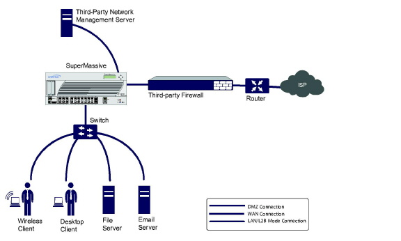
This method is useful in networks where there is an existing firewall that will remain in place, but you wish to utilize the SonicWALL’s UTM services without making major changes to the network. By placing the SonicWALL in Layer 2 Bridge mode, the X0 and X1 interfaces become part of the same broadcast domain/network (that of the X1 WAN interface).
To configure the SonicWALL appliance for this scenario, navigate to the Network > Interfaces page and click on the configure icon for the X0 LAN interface. On the X0 Settings page, set the IP Assignment to ‘Layer 2 Bridged Mode’ and set the Bridged To: interface to ‘X1’. Also make sure that the interface is configured for HTTP and SNMP so it can be managed from the DMZ by the existing firewall. Click OK to save and activate the change.
You will also need to make sure to modify the firewall access rules to allow traffic from the LAN to WAN, and from the WAN to the LAN, otherwise traffic will not pass successfully. This example refers to a SonicWALL UTM appliance installed with a third-party network management server that can be used to manage the switches as well as some aspects of the SonicWALL UTM appliance. You may also need to modify routing information on your firewall if your network management server is placed on the DMZ.
The following diagram depicts a network where the SonicWALL is added to the perimeter for the purpose of providing security services (the network may or may not have an existing firewall between the SonicWALL and the router).
In this scenario, everything below the SonicWALL (the Primary Bridge Interface segment) will generally be considered as having a lower level of trust than everything to the left of the SonicWALL (the Secondary Bridge Interface segment). For that reason, it would be appropriate to use X1 (Primary WAN) as the Primary Bridge Interface.
Traffic from hosts connected to the Secondary Bridge Interface (LAN) would be permitted outbound through the SonicWALL to their gateways (VLAN interfaces on the L3 switch and then through the router), while traffic from the Primary Bridge Interface (WAN) would, by default, not be permitted inbound.
If there were public servers, for example, a mail and Web server, on the Secondary Bridge Interface (LAN) segment, an Access Rule allowing WAN->LAN traffic for the appropriate IP addresses and services could be added to allow inbound traffic to those servers.
This diagram depicts a network where the SonicWALL will act as the perimeter security device and secure wireless platform. Simultaneously, it will provide L2 Bridge security between the workstation and server segments of the network without having to readdress any of the workstation or servers.
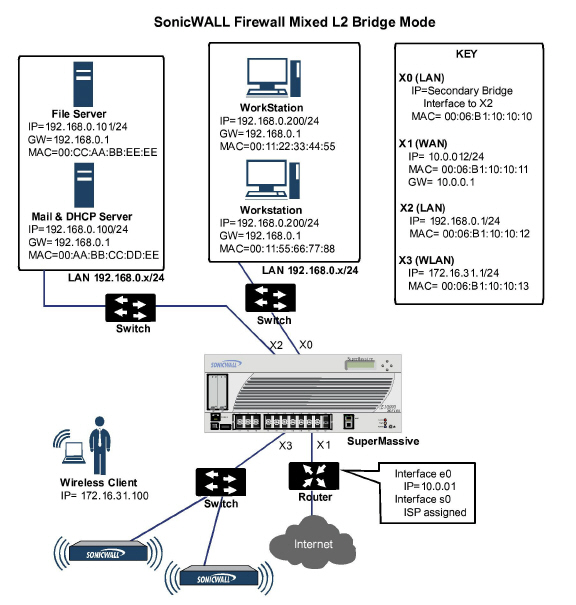
This typical inter-departmental Mixed Mode topology deployment demonstrates how the SonicWALL can simultaneously Bridge and route/NAT. Traffic to/from the Primary Bridge Interface (Server) segment from/to the Secondary Bridge Interface (Workstation) segment will pass through the L2 Bridge.
Since both interfaces of the Bridge-Pair are assigned to a Trusted (LAN) zone, the following will apply:
• All traffic will be allowed by default, but Access Rules could be constructed as needed.
Consider, for the point of contrast, what would occur if the X2 (Primary Bridge Interface) was instead assigned to a Public (DMZ) zone: All the Workstations would be able to reach the Servers, but the Servers would not be able to initiate communications to the Workstations. While this would probably support the traffic flow requirements (i.e. Workstations initiating sessions to Servers), it would have two undesirable effects:
The DHCP server would be in the DMZ. DHCP requests from the Workstations would pass through the L2 Bridge to the DHCP server (192.168.0.100), but the DHCP offers from the server would be dropped by the default DMZ->LAN Deny Access Rule. An Access Rule would have to be added, or the default modified, to allow this traffic from the DMZ to the LAN.
Security services directionality would be classified as Outgoing for traffic from the Workstations to the Server since the traffic would have a Trusted source zone and a Public destination zone. This might be sub-optimal since it would provide less scrutiny than the Incoming or (ideally) Trust classifications.
• Security services directionality would be classified as Trust, and all signatures (Incoming, Outgoing, and Bidirectional) will be applied, providing the highest level of security to/from both segments.
For detailed instructions on configuring interfaces in Layer 2 Bridge Mode, see Configuring Layer 2 Bridge Mode
Layer 2 Bridge Mode with High Availability
This method is appropriate in networks where both High Availability and Layer 2 Bridge Mode are desired. This example is for SonicWALL SuperMassives, and assumes the use of switches with VLANs configured.
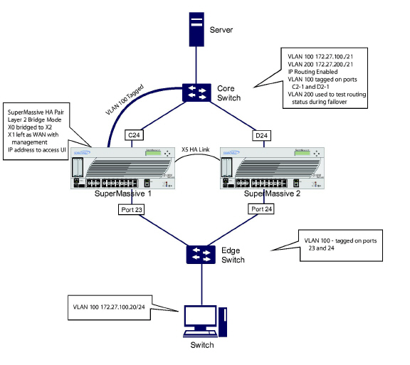
The SonicWALL HA pair consists of two SonicWALL SuperMassives, connected together on port X5, the designated HA port. Port X1 on each appliance is configured for normal WAN connectivity and is used for access to the management interface of that device. Layer 2 Bridge Mode is implemented with port X0 bridged to port X2.
When setting up this scenario, there are several things to take note of on both the SonicWALLs and the switches.
On the SonicWALL appliances:
• Do not enable the Virtual MAC option when configuring High Availability. In a Layer 2 Bridge Mode configuration, this function is not useful.
• Enabling Preempt Mode is not recommended in an inline environment such as this. If Preempt Mode is required, follow the recommendations in the documentation for your switches, as the trigger and failover time values play a key role here.
• Consider reserving an interface for the management network (this example uses X1). If it is necessary to assign IP addresses to the bridge interfaces for probe purposes or other reasons, SonicWALL recommends using the management VLAN network assigned to the switches for security and administrative purposes. Note that the IP addresses assigned for HA purposes do not directly interact with the actual traffic flow.
On the switches:
• Using multiple tag ports: As shown in the above diagram, two tag (802.1q) ports were created for VLAN 100 on both the Edge switch (ports 23 and 24) and Core switch (C24 - D24). The appliances are connected inline between these two switches. In a high performance environment, it is usually recommended to have Link Aggregation/ Port Trunking, Dynamic LACP, or even a completely separate link designated for such a deployment (using OSPF), and the fault tolerance of each of the switches must be considered. Consult your switch documentation for more information.
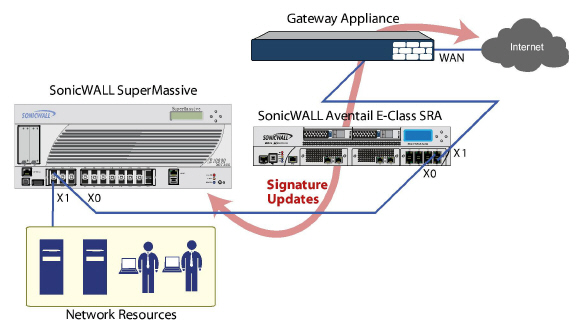
Layer 2 Bridge Mode with e VPN
This sample topology covers the proper installation of a SonicWALL UTM device into your existing SonicWALL EX-Series SSL VPN or SonicWALL SSL VPN networking environment. By placing the UTM appliance into Layer 2 Bridge Mode, with an internal, private connection to the SSL VPN appliance, you can scan for viruses, spyware, and intrusions in both directions. In this scenario the SonicWALL SuperMassive is not used for security enforcement, but instead for bidirectional scanning, blocking viruses and spyware, and stopping intrusion attempts. When programmed correctly, the UTM appliance will not interrupt network traffic, unless the behavior or content of the traffic is determined to be undesirable. Both one- and two-port deployments of the SonicWALL SuperMassive are covered in this section.
WAN to LAN Access Rules
Because the UTM appliance will be used in this deployment scenario only as an enforcement point for anti-virus, anti-spyware and intrusion prevention, its existing security policy must be modified to allow traffic to pass in both directions between the WAN and LAN.
On the Firewall > Access Rules page, click the Configure icon for the intersection of WAN to LAN traffic. Click the Configure icon next to the default rule that implicitly blocks uninitiated traffic from the WAN to the LAN. In the Edit Rule window, select Allow for the Action setting, and then click OK.
Configure the Network Interfaces and Activate L2B Mode
In this scenario the WAN interface is used for the following:
• Access to the management interface for the administrator
• Subscription service updates on MySonicWALL
• The default route for the device and subsequently the “next hop” for the internal traffic of the SSL VPN appliance (this is why the UTM device WAN interface must be on the same IP segment as the internal interface of the SSL VPN appliance)
The LAN interface on the UTM appliance is used to monitor the unencrypted client traffic coming from the external interface of the SSL VPN appliance. This is the reason for running in Layer 2 Bridge Mode (instead of reconfiguring the external interface of the SSL VPN appliance to see the LAN interface as the default route).
On the Network > Interfaces page of the SonicOS management interface, click the Configure icon for the WAN interface, and then assign it an address that can access the Internet so that the appliance can obtain signature updates and communicate with NTP.
The gateway and internal/external DNS address settings will match those of your SSL VPN appliance:
• IP address: This must match the address for the internal interface on the SSL VPN appliance.
• Subnet Mask, Default Gateway, and DNS Server(s): Make these addresses match your SSL VPN appliance settings.
For the Management setting, select the HTTPS and Ping check boxes. Click OK to save and activate the changes.
To configure the LAN interface settings, navigate to the Network > Interfaces page and click the Configure icon for the LAN interface.
For the IP Assignment setting, select Layer 2 Bridged Mode. For the Bridged to setting, select X1.
If you also need to pass VLAN tagged traffic, supported on SonicWALL SuperMassives, click the VLAN Filtering tab and add all of the VLANs that will need to be passed.
Click OK to save and activate the change. You may be automatically disconnected from the UTM appliance’s management interface. You can now disconnect your management laptop or desktop from the UTM appliance’s X0 interface and power the UTM appliance off before physically connecting it to your network.
Install the SonicWALL SuperMassive between the network and SSL VPN appliance
Regardless of your deployment method (single- or dual-homed), the SonicWALL SuperMassive should be placed between the X0/LAN interface of the SSL VPN appliance and the connection to your internal network. This allows the device to connect out to SonicWALL’s licensing and signature update servers, and to scan the decrypted traffic from external clients requesting access to internal network resources.
Dual-Homed – If your SSL VPN appliance is in two-port mode behind a third-party firewall, it is dual-homed.
To connect a dual-homed SSL VPN appliance, follow these steps:
Step 1 Cable the X0/LAN port on the UTM appliance to the X0/LAN port on the SSL VPN appliance.
Step 2 Cable the X1/WAN port on the UTM appliance to the port where the SSL VPN was previously connected.
Step 3 Power on the UTM appliance.
Single-Homed – If your SSL VPN appliance is in one-port mode in the DMZ of a third-party firewall, it is single-homed.

To connect a single-homed SSL VPN appliance, follow these steps:
Step 1 Cable the X0/LAN port on the UTM appliance to the X0/LAN port of the SSL VPN appliance.
Step 2 Cable the X1/WAN port on the UTM appliance to the port where the SSL VPN was previously connected.
Step 3 Power on the UTM appliance.
Configure or verify settings
From a management station inside your network, you should now be able to access the management interface on the UTM appliance using its WAN IP address.
Make sure that all security services for the SonicWALL SuperMassive are enabled. See Licensing Services and Activating UTM Services on Each Zone.
SonicWALL Content Filtering Service must be disabled before the device is deployed in conjunction with a SonicWALL Aventail SSL VPN appliance. On the Network > Zones page, click Configure next to the LAN (X0) zone, clear the Enforce Content Filtering Service check box and then click OK.
If you have not yet changed the administrative password on the SonicWALL SuperMassive, you can do so on the System > Administration page.
To test access to your network from an external client, connect to the SSL VPN appliance and log in. Once connected, attempt to access to your internal network resources. If there are any problems, review your configuration and see the Configuring the Common Settings for L2 Bridge Mode Deployments.
Configuring Layer 2 Bridge Mode
See the following sections:
• Configuration Task List for Layer 2 Bridge Mode
• Configuring the Common Settings for L2 Bridge Mode Deployments
• Configuring Layer 2 Bridge Mode Procedure
• VLAN Integration with Layer 2 Bridge Mode
• VPN Integration with Layer 2 Bridge Mode
• Choose a topology that suits your network
• Configuring the Common Settings for L2 Bridge Mode Deployments
– License UTM services
– Disable DHCP server
– Configure and enable SNMP and HTTP/HTTPS management
– Enable syslog
– Activate UTM services on affected zones
– Create firewall access rules
– Configure log settings
– Configure wireless zone settings
• Configuring the Primary Bridge Interface
– Select the zone for the Primary Bridge Interface
– Activate management
– Activate security services
• Configuring the Secondary Bridge Interface
– Select the zone for the Secondary Bridge Interface
– Activate management
– Activate security services
• Apply security services to the appropriate zones
The following settings need to be configured on your SonicWALL SuperMassive prior to using it in most of the Layer 2 Bridge Mode topologies.
When the appliance is successfully registered, go to the System > Licenses page and click Synchronize under Manage Security Services Online. This will contact the SonicWALL licensing server and ensure that the appliance is properly licensed.
To check licensing status, go to the System > Status page and view the license status of all the UTM services (Gateway Anti-Virus, Anti-Spyware, and Intrusion Prevention).
Disabling DHCP Server
When using a SonicWALL SuperMassive in Layer 2 Bridge Mode in a network configuration where another device is acting as the DHCP server, you must first disable its internal DHCP engine, which is configured and running by default. On the Network > DHCP Server page, clear the Enable DHCP Server check box, and then click on the Accept button at the top of the screen
Configuring SNMP Settings
On the System > Administration page, make sure the checkbox next to Enable SNMP is checked, and then click on the Accept button at the top of the screen.Then, click the Configure button. On the SNMP Settings page, enter all the relevant information for your UTM appliance: the GET and TRAP SNMP community names that the SNMP server expects, and the IP address of the SNMP server. Click OK to save and activate the changes.Enabling SNMP and HTTPS on the Interfaces
On the Network > Interfaces page, enable SNMP and HTTP/HTTPS on the interface through which you will be managing the appliance.
On the Log > Syslog page, click on the Add button and create an entry for the syslog server. Click OK to save and activate the change.
Activating UTM Services on Each Zone
On the Network > Zones page, for each zone you will be using, make sure that the UTM services are activated.Then, on the Security Services page for each UTM service, activate and configure the settings that are most appropriate for your environment.
Creating Firewall Access Rules
If you plan to manage the appliance from a different zone, or if you will be using a third-party network management server for management, SNMP, or syslog services, create access rules for traffic between the zones. On the Firewall > Access Rules page, click on the icon for the intersection of the zone of the server and the zone that has users and servers (your environment may have more than one of these intersections). Create a new rule to allow the server to communicate with all devices in that zone.
Configuring Log Settings
On the Log > Categories page, set the Logging Level to Informational and the Alert Level to Critical. Click Accept to save and activate the change.
Then, go to the Log > Name Resolution page and set the Name Resolution Method to DNS then NetBios. Click Accept to save and activate the change.
Refer to the L2 Bridge Interface Zone Selection for choosing a topology that best suits your network. In this example, we will be using a topology that most closely resembles the Simple L2 Bridge Topology.
Choose an interface to act as the Primary Bridge Interface. Refer to the L2 Bridge Interface Zone Selection for information in making this selection. In this example, we will use X1 (automatically assigned to the Primary WAN):
Configuring the Primary Bridge Interface
Step 1 Select the Network tab, Interfaces folder from the navigation panel.
Step 2 Click the Configure  icon in the right column of the X1 (WAN) interface.
Step 3 Configure the interface with a Static IP address (e.g. 192.168.0.12).
Note The Primary Bridge Interface must have a Static IP assignment.
Step 4 Configure the default gateway. This is required for the security appliance itself to reach the Internet. (This applies only to WAN interfaces.)
Step 5 Configure the DNS server. (This applies only to WAN interfaces.)
Step 6 Configure management (HTTP, HTTPS, Ping, SNMP, SSH, User Logins, HTTP Redirects).
Click OK.Choose an interface to act as the Secondary Bridge Interface. Refer to the L2 Bridge Interface Zone Selection for information in making this selection. In this example, we will use X0 (automatically assigned to the LAN):
Configuring the Secondary Bridge Interface
Step 1 On the Network > Interfaces page, click the Configure  icon in the right column of the X0 (LAN) interface.
Step 2 In the IP Assignment drop-down list, select Layer 2 Bridged Mode.
Step 3 In the Bridged to drop-down list, select the X1 interface.
Step 4 Configure management (HTTP, HTTPS, Ping, SNMP, SSH, User Logins, HTTP Redirects).
Step 5 You may optionally enable the Block all non-IPv4 traffic setting to prevent the L2 bridge from passing non-IPv4 traffic.
VLAN Filtering
• You may also optionally navigate to the VLAN Filtering tab to control VLAN traffic through the L2 bridge. By default, all VLANs are allowed:
– Select Block listed VLANs (blacklist) from the drop-down list and add the VLANs you wish to block from the left pane to the right pane. All VLANs added to the right pane will be blocked, and all VLANs remaining in the left pane will be allowed.
– Select Allow listed VLANs (whitelist) from the drop-down list and add the VLANs you wish to explicitly allow from the left pane to the right pane. All VLANs added to the right pane will be allowed, and all VLANs remaining in the left pane will be blocked.
Step 6 Click OK.
The Network > Interfaces page displays the updated configuration:
You may now apply security services to the appropriate zones, as desired. In this example, they should be applied to the LAN, WAN, or both zones.
VLANs are supported on SonicWALL SuperMassives. When a packet with a VLAN tag arrives on a physical interface, the VLAN ID is evaluated to determine if it is supported. The VLAN tag is stripped, and packet processing continues as it would for any other traffic. A simplified view of the inbound and outbound packet path includes the following potentially reiterative steps:
• IP validation and reassembly
• Decapsulation (802.1q, PPP)
• Decryption
• Connection cache lookup and management
• Route policy lookup
• NAT Policy lookup
• Access Rule (policy) lookup
• Bandwidth management
• NAT translation
• Advanced Packet Handling (as applicable)
– TCP validation
– Management traffic handling
– Content Filtering
– Transformations and flow analysis (on SonicWALL SuperMassives): H.323, SIP, RTSP, ILS/LDAP, FTP, Oracle, NetBIOS, Real Audio, TFTP
– IPS and GAV
At this point, if the packet has been validated as acceptable traffic, it is forwarded to its destination. The packet egress path includes:
• Encryption
• Encapsulation
• IP fragmentation
On egress, if the route policy lookup determines that the gateway interface is a VLAN subinterface, the packet is tagged (encapsulated) with the appropriate VLAN ID header. The creation of VLAN subinterfaces automatically updates the SonicWALL’s routing policy table:
The auto-creation of NAT policies, Access Rules with regard to VLAN subinterfaces behave exactly the same as with physical interfaces. Customization of the rules and policies that govern the traffic between VLANs can be performed with customary SonicOS ease and efficiency.
When creating a zone (either as part of general administration, or as a step in creating a subinterface), a checkbox will be presented on the zone creation page to control the auto-creation of a GroupVPN for that zone. By default, only newly created Wireless type zones will have ‘Create GroupVPN for this zone’ enabled, although the option can be enabled for other zone types by selecting the checkbox during creation.
Management of security services between VLAN subinterfaces is accomplished at the zone level. All security services are configurable and applicable to zones comprising physical interfaces, VLAN subinterfaces, or combinations of physical and VLAN subinterfaces.
Gateway Anti-Virus and Intrusion Prevention Services between the different workgroups can easily be employed with the use of VLAN segmentation, obviating the need for dedicated physical interfaces for each protected segment.
VLAN support enables organizations to offer meaningful internal security (as opposed to simple packet filtering) between various workgroups, and between workgroups and server farms without having to use dedicated physical interfaces on the SonicWALL.
Here the ability to assign VLAN subinterfaces to the WAN zone, and to use the WAN client mode (only Static addressing is supported on VLAN subinterfaces assigned to the WAN zone) is illustrated, along with the ability to support WAN Load Balancing and failover. Also demonstrated is the distribution of SonicPoints throughout the network by means of connecting them to access mode VLAN ports on workgroup switches. These switches are then backhauled to the core switch, which then connects all the VLANs to the appliance via a trunk link.
When configuring a VPN on an interface that is also configured for Layer 2 Bridge mode, you must configure an additional route to ensure that incoming VPN traffic properly traverses the SonicWALL SuperMassive. Navigate to the Network > Routing page, scroll to the bottom of the page, and click on the Add button. In the Add Route Policy window, configure the route as follows:
• Source: ANY
• Destination: custom-VPN-address-object (This is the address object for the local VPN tunnel IP address range.)
• Service: ANY
• Gateway: 0.0.0.0
• Interface: X0