 icon in the right column of the X1 (WAN) interface.
U0_interface
The SonicWALL TZ 200 security appliances support an external 3G/mobile or analog modem interface. This interface is listed at the bottom of the Interface Settings table as the U0 interface. A number of the settings for the external interface can be configured from the Network > Interfaces page, but it can be more thoroughly configured using the pages on the 3G or Modem tab in the left-side navigation bar.
For complete information on configuring a 3G or analog modem external interface, see 3G/4G/Modem.
Specifying the WAN Connection Model
Note The WAN Connection Model drop-down menu is only displayed when the U0 interface is configured for a 3G/mobile external interface. This menu item is not displayed when the U0 interface is configured for an analog modem.
To configure the WAN connection model, navigate to the Network > Interfaces page and select one of the following options in the WAN Connection Model drop-down menu:
• 3G only - The WAN interface is disabled and the 3G interface is used exclusively.
• Ethernet only - The 3G interface is disabled and the WAN interface is used exclusively.
• Ethernet with 3G Failover - The WAN interface is used as the primary interface and the 3G interface is disabled. If the WAN connection fails, the 3G interface is enabled and a 3G connection is automatically initiated.
For a detailed explanation of the behavior of the Ethernet with 3G Failover setting see Understanding 3G/4G Connection Types.
PortShield architecture enables you to configure some or all of the LAN ports into separate security contexts, providing protection not only from the WAN and DMZ, but between devices inside your network as well. In effect, each context has its own wire-speed PortShield that enjoys the protection of a dedicated, deep packet inspection firewall.
PortShield is supported on SonicWALL TZ Series, NSA 240, and NSA 2400MX appliances.
Tip Zones can always be applied to multiple interfaces in the Network > Interfaces page, even without the use of PortShield groupings. However, these interfaces will not share the same network subnet unless they are grouped using PortShield.
You can assign any combination of ports into a PortShield interface. All ports you do not assign to a PortShield interface are assigned to the LAN interface.
To configure a PortShield interface, perform the following steps:
Step 1 Click on the Network > Interfaces page.
Step 2 Click the Configure button for the interface you want to configure. The Edit Interface window displays.
Step 3 In the Zone pulldown menu, select on a zone type option to which you want to map the interface.
Note You can add PortShield interfaces only to Trusted, Public, and Wireless zones.
Step 4 In the IP Assignment pulldown menu, select PortShield Switch Mode.
Step 5 In the PortShield to pulldown menu, select the interface you want to map this port to. Only ports that match the zone you have selected are displayed.
VLAN subinterfaces are supported on SonicWALL NSA series appliances. When you add a VLAN subinterface, you need to assign it to a zone, assign it a VLAN Tag, and assign it to a physical interface. Based on your zone assignment, you configure the VLAN subinterface the same way you configure a physical interface for the same zone.
Adding a virtual interface
Step 1 In the left-navigation menu click on Network and then Interfaces to display the Network > Interfaces page.
Step 2 At the bottom of the Interface Settings table, click Add Interface. The Edit Interface window displays.
Step 3 Select a zone to assign to the interface. You can select LAN, WAN, DMZ, WLAN, or a custom zone. The zone assignment does not have to be the same as the parent (physical) interface. In fact, the parent interface can even remain Unassigned.
Your configuration choices for the network settings of the subinterface depend on the zone you select.
• LAN, DMZ, or a custom zone of Trusted type: Static or Transparent
• WLAN or a custom Wireless zone: static IP only (no IP Assignment list).
Step 4 Assign a VLAN tag (ID) to the subinterface. Valid VLAN ID’s are 1 to 4095, although some switches reserve VLAN 1 for native VLAN designation. You will need to create a VLAN subinterface with a corresponding VLAN ID for each VLAN you wish to secure with your security appliance.
Step 5 Declare the parent (physical) interface to which this subinterface will belong. There is no per-interface limit to the number of subinterfaces you can assign – you may assign subinterfaces up to the system limit.
Step 6 Configure the subinterface network settings based on the zone you selected. See the interface configuration instructions earlier in this chapter:
– Configuring the Static Interfaces
– Configuring Advanced Settings for the Interface
– Configuring Interfaces in Transparent Mode
– Configuring Wireless Interfaces
• Configuring the WLAN Interface (SonicWALL TZ series wireless appliances)
– Configuring SonicWALL PortShield Interfaces (TZ series, NSA 240, and NSA 2400MX)
• Configuring the U0 External 3G/Modem Interface
• Configuring SonicWALL PortShield Interfaces (TZ series, NSA 240, and NSA 2400MX)
– Configuring VLAN Subinterfaces (SonicWALL NSA series appliances)
Step 7 Select the management and user-login methods for the subinterface.
Step 8 Click OK.
Configuring Layer 2 Bridge Mode
See the following sections:
• Configuration Task List for Layer 2 Bridge Mode
• Configuring Layer 2 Bridge Mode Procedure
• VLAN Integration with Layer 2 Bridge Mode (SonicWALL NSA series appliances)
• VPN Integration with Layer 2 Bridge Mode
• Choose a topology that suits your network
• Configuring the Common Settings for L2 Bridge Mode Deployments
– License UTM services
– Disable DHCP server
– Configure and enable SNMP and HTTP/HTTPS management
– Enable syslog
– Activate UTM services on affected zones
– Create firewall access rules
– Configure log settings
– Configure wireless zone settings
• Configuring the Primary Bridge Interface
– Select the zone for the Primary Bridge Interface
– Activate management
– Activate security services
• Configuring the Secondary Bridge Interface
– Select the zone for the Secondary Bridge Interface
– Activate management
– Activate security services
• Apply security services to the appropriate zones
The following settings need to be configured on your SonicWALL UTM appliance prior to using it in most of the Layer 2 Bridge Mode topologies.
When the appliance is successfully registered, go to the System > Licenses page and click Synchronize under Manage Security Services Online. This will contact the SonicWALL licensing server and ensure that the appliance is properly licensed.
To check licensing status, go to the System > Status page and view the license status of all the UTM services (Gateway Anti-Virus, Anti-Spyware, and Intrusion Prevention).
Disabling DHCP Server
When using a SonicWALL UTM appliance in Layer 2 Bridge Mode in a network configuration where another device is acting as the DHCP server, you must first disable its internal DHCP engine, which is configured and running by default. On the Network > DHCP Server page, clear the Enable DHCP Server check box, and then click on the Accept button at the top of the screen.
Configuring SNMP Settings
On the System > Administration page, make sure the checkbox next to Enable SNMP is checked, and then click on the Accept button at the top of the screen.
Then, click the Configure button. On the SNMP Settings page, enter all the relevant information for your UTM appliance: the GET and TRAP SNMP community names that the SNMP server expects, and the IP address of the SNMP server. Click OK to save and activate the changes.
Enabling SNMP and HTTPS on the Interfaces
On the Network > Interfaces page, enable SNMP and HTTP/HTTPS on the interface through which you will be managing the appliance.
Enabling Syslog
On the Log > Syslog page, click on the Add button and create an entry for the syslog server. Click OK to save and activate the change.
Activating UTM Services on Each Zone
On the Network > Zones page, for each zone you will be using, make sure that the UTM services are activated.
Then, on the Security Services page for each UTM service, activate and configure the settings that are most appropriate for your environment.
An example of the Gateway Anti-Virus settings is shown below:
An example of the Intrusion Prevention settings is shown below:
An example of the Anti-Spyware settings is shown below:
Creating Firewall Access Rules
If you plan to manage the appliance from a different zone, or if you will be using a server such as the HP PCM+/NIM server for management, SNMP, or syslog services, create access rules for traffic between the zones. On the Firewall > Access Rules page, click on the icon for the intersection of the zone of the server and the zone that has users and servers (your environment may have more than one of these intersections). Create a new rule to allow the server to communicate with all devices in that zone.
Configuring Log Settings
On the Log > Categories page, set the Logging Level to Informational and the Alert Level to Critical. Click Accept to save and activate the change.
Then, go to the Log > Name Resolution page and set the Name Resolution Method to DNS then NetBios. Click Accept to save and activate the change.
Configuring Wireless Zone Settings
In the case where you are using a HP PCM+/NIM system, if it will be managing a HP ProCurve switch on an interface assigned to a WLAN/Wireless zone, you will need to deactivate two features, otherwise you will not be able to manage the switch. Go to the Network > Zones page and select your Wireless zone. On the Wireless tab, clear the checkboxes next to Only allow traffic generated by a SonicPoint and WiFiSec Enforcement. Click OK to save and activate the change.
Refer to the L2 Bridge Interface Zone Selection for choosing a topology that best suits your network. In this example, we will be using a topology that most closely resembles the Simple L2 Bridge Topology.
Choose an interface to act as the Primary Bridge Interface. Refer to the L2 Bridge Interface Zone Selection for information in making this selection. In this example, we will use X1 (automatically assigned to the Primary WAN):
Configuring the Primary Bridge Interface
Step 1 Select the Network tab, Interfaces folder from the navigation panel.
Step 2 Click the Configure icon in the right column of the X1 (WAN) interface.
Step 3 Configure the interface with a Static IP address (e.g. 192.168.0.12).
Note The Primary Bridge Interface must have a Static IP assignment.
Step 4 Configure the default gateway. This is required for the security appliance itself to reach the Internet. (This applies only to WAN interfaces.)
Step 5 Configure the DNS server. (This applies only to WAN interfaces.)
Step 6 Configure management (HTTP, HTTPS, Ping, SNMP, SSH, User Logins, HTTP Redirects).
Step 7 Click OK.
Choose an interface to act as the Secondary Bridge Interface. Refer to the L2 Bridge Interface Zone Selection for information in making this selection. In this example, we will use X0 (automatically assigned to the LAN):
Configuring the Secondary Bridge Interface
Step 1 On the Network > Interfaces page, click the Configure  icon in the right column of the X0 (LAN) interface.
Step 2 In the IP Assignment drop-down list, select Layer 2 Bridged Mode.
Step 3 In the Bridged to drop-down list, select the X1 interface.
Step 4 Configure management (HTTP, HTTPS, Ping, SNMP, SSH, User Logins, HTTP Redirects).
Step 5 You may optionally enable the Block all non-IPv4 traffic setting to prevent the L2 bridge from passing non-IPv4 traffic.
VLAN Filtering (SonicWALL NSA series appliances)
• You may also optionally navigate to the VLAN Filtering tab to control VLAN traffic through the L2 bridge. By default, all VLANs are allowed:
– Select Block listed VLANs (blacklist) from the drop-down list and add the VLANs you wish to block from the left pane to the right pane. All VLANs added to the right pane will be blocked, and all VLANs remaining in the left pane will be allowed.
– Select Allow listed VLANs (whitelist) from the drop-down list and add the VLANs you wish to explicitly allow from the left pane to the right pane. All VLANs added to the right pane will be allowed, and all VLANs remaining in the left pane will be blocked.
Step 6 Click OK.
The Network > Interfaces page displays the updated configuration:
You may now apply security services to the appropriate zones, as desired. In this example, they should be applied to the LAN, WAN, or both zones.
VLANs are supported on SonicWALL NSA series appliances. When a packet with a VLAN tag arrives on a physical interface, the VLAN ID is evaluated to determine if it is supported. The VLAN tag is stripped, and packet processing continues as it would for any other traffic. A simplified view of the inbound and outbound packet path includes the following potentially reiterative steps:
• IP validation and reassembly
• Decapsulation (802.1q, PPP)
• Decryption
• Connection cache lookup and management
• Route policy lookup
• NAT Policy lookup
• Access Rule (policy) lookup
• Bandwidth management
• NAT translation
• Advanced Packet Handling (as applicable)
– TCP validation
– Management traffic handling
– Content Filtering
– Transformations and flow analysis (on SonicWALL NSA series appliances): H.323, SIP, RTSP, ILS/LDAP, FTP, Oracle, NetBIOS, Real Audio, TFTP
– IPS and GAV
At this point, if the packet has been validated as acceptable traffic, it is forwarded to its destination. The packet egress path includes:
• Encryption
• Encapsulation
• IP fragmentation
On egress, if the route policy lookup determines that the gateway interface is a VLAN subinterface, the packet is tagged (encapsulated) with the appropriate VLAN ID header. The creation of VLAN subinterfaces automatically updates the SonicWALL’s routing policy table:
The auto-creation of NAT policies, Access Rules with regard to VLAN subinterfaces behave exactly the same as with physical interfaces. Customization of the rules and policies that govern the traffic between VLANs can be performed with customary SonicOS ease and efficiency.
When creating a zone (either as part of general administration, or as a step in creating a subinterface), a checkbox will be presented on the zone creation page to control the auto-creation of a GroupVPN for that zone. By default, only newly created Wireless type zones will have ‘Create GroupVPN for this zone’ enabled, although the option can be enabled for other zone types by selecting the checkbox during creation.
Management of security services between VLAN subinterfaces is accomplished at the zone level. All security services are configurable and applicable to zones comprising physical interfaces, VLAN subinterfaces, or combinations of physical and VLAN subinterfaces.
Gateway Anti-Virus and Intrusion Prevention Services between the different workgroups can easily be employed with the use of VLAN segmentation, obviating the need for dedicated physical interfaces for each protected segment.
VLAN support enables organizations to offer meaningful internal security (as opposed to simple packet filtering) between various workgroups, and between workgroups and server farms without having to use dedicated physical interfaces on the SonicWALL.
Here the ability to assign VLAN subinterfaces to the WAN zone, and to use the WAN client mode (only Static addressing is supported on VLAN subinterfaces assigned to the WAN zone) is illustrated, along with the ability to support WAN Load Balancing and failover. Also demonstrated is the distribution of SonicPoints throughout the network by means of connecting them to access mode VLAN ports on workgroup switches. These switches are then backhauled to the core switch, which then connects all the VLANs to the appliance via a trunk link.
When configuring a VPN on an interface that is also configured for Layer 2 Bridge mode, you must configure an additional route to ensure that incoming VPN traffic properly traverses the SonicWALL security appliance. Navigate to the Network > Routing page, scroll to the bottom of the page, and click on the Add button. In the Add Route Policy window, configure the route as follows:
• Source: ANY
• Destination: custom-VPN-address-object (This is the address object for the local VPN tunnel IP address range.)
• Service: ANY
• Gateway: 0.0.0.0
• Interface: X0
Configuring IPS Sniffer Mode (SonicWALL NSA series appliances)
To configure the SonicWALL NSA appliance for IPS Sniffer Mode, you will use two interfaces in the same zone for the L2 Bridge-Pair. You can use any interfaces except the WAN interface. For this example, we will use X2 and X3 for the Bridge-Pair, and configure them to be in the LAN zone. The WAN interface (X1) is used by the SonicWALL appliance for access to the SonicWALL Data Center as needed. The mirrored port on the switch will connect to one of the interfaces in the Bridge-Pair.
This section contains the following topics:
• Configuration Task List for IPS Sniffer Mode
• Configuring the Primary Bridge Interface
• Configuring the Secondary Bridge Interface
• Enabling and Configuring SNMP
• Configuring Security Services (Unified Threat Management)
• Connecting the Mirrored Switch Port to a IPS Sniffer Mode Interface
• Connecting and Configuring the WAN Interface to the Data Center
• Configure the Primary Bridge Interface
– Select LAN as the Zone for the Primary Bridge Interface
– Assign a static IP address
• Configure the Secondary Bridge Interface
– Select LAN as the Zone for the Secondary Bridge Interface
– Enable the L2 Bridge to the Primary Bridge interface
• Enable SNMP and configure the IP address of the SNMP manager system where traps can be sent
• Configure Security Services (UTM) for LAN traffic
• Configure logging alert settings to “Alert” or below
• Connect the mirrored port on the switch to either one of the interfaces in the Bridge-Pair
• Connect and configure the WAN to allow access to dynamic signature data over the Internet
Step 1 Select the Network tab, Interfaces folder from the navigation panel.
Step 2 Click the Configure icon in the right column of interface X2.
Step 3 In the Edit Interface dialog box on the General tab, select LAN from the Zone drop-down list.
Note that you do not need to configure settings on the Advanced or VLAN Filtering tabs.
Step 4 For IP Assignment, select Static from the drop-down list.
Step 5 Configure the interface with a static IP Address (e.g. 10.1.2.3). The IP address you choose should not collide with any of the networks that are seen by the switch.
Note The Primary Bridge Interface must have a static IP assignment.
Step 6 Configure the Subnet Mask.
Step 7 Type in a descriptive comment.
Step 8 Select management options for the interface (HTTP, HTTPS, Ping, SNMP, SSH, User Logins, HTTP Redirects).
Step 9 Click OK.
Our example continues with X3 as the secondary bridge interface.
Step 1 Select the Network tab, Interfaces folder from the navigation panel.
Step 2 Click the Configure icon in the right column of the X3 interface.
Step 3 In the Edit Interface dialog box on the General tab, select LAN from the Zone drop-down list.
Note that you do not need to configure settings on the Advanced or VLAN Filtering tabs.
Step 4 In the IP Assignment drop-down list, select Layer 2 Bridged Mode.
Step 5 In the Bridged to drop-down list, select the X2 interface.
Step 6 Do not enable the Block all non-IPv4 traffic setting if you want to monitor non-IPv4 traffic.
Step 7 Select Never route traffic on this bridge-pair to ensure that the traffic from the mirrored switch port is not sent back out onto the network. (The Never route traffic on this bridge-pair setting is known as Captive-Bridge Mode.)
Step 8 Select Only sniff traffic on this bridge-pair to enable sniffing or monitoring of packets that arrive on the L2 Bridge from the mirrored switch port.
Step 9 Select Disable stateful-inspection on this bridge-pair to exempt these interfaces from stateful high availability inspection. If Deep Packet Inspection services are enabled for these interfaces, the DPI services will continue to be applied.
Step 10 Configure management (HTTP, HTTPS, Ping, SNMP, SSH, User Logins, HTTP Redirects).
Step 11 Click OK.
When SNMP is enabled, SNMP traps are automatically triggered for many events that are generated by SonicWALL Security Services such as Intrusion Prevention and Gateway Anti-Virus.
More than 50 IPS and GAV events currently trigger SNMP traps. The SonicOS Log Event Reference Guide contains a list of events that are logged by SonicOS, and includes the SNMP trap number where applicable. The guide is available online at
http://www.sonicwall.com/us/Support.html by typing Log Event into the Search field at the top of the page.
To determine the traps that are possible when using IPS Sniffer Mode with Intrusion Prevention enabled, search for Intrusion in the table found in the Index of Log Event Messages section in the SonicOS Log Event Reference Guide. The SNMP trap number, if available for that event, is printed in the SNMP Trap Type column of the table.
To determine the possible traps with Gateway Anti-Virus enabled, search the table for Security Services, and view the SNMP trap number in the SNMP Trap Type column.
To enable and configure SNMP:
Step 1 Select the System tab, Administration folder from the navigation panel.
Step 2 Scroll down to the Advanced Management section.
Step 3 Select the Enable SNMP checkbox. The Configure button becomes active.
Step 4 Click Configure. The SNMP Settings dialog box is displayed.
Step 5 In the SNMP Settings dialog box, for System Name, type the name of the SNMP manager system that will receive the traps sent from the SonicWALL.
Step 6 Enter the name or email address of the contact person for the SNMP Contact
Step 7 Enter a description of the system location, such as “3rd floor lab”.
Step 8 Enter the system’s asset number.
Step 9 For Get Community Name, type the community name that has permissions to retrieve SNMP information from the SonicWALL, e.g. public.
Step 10 For Trap Community Name, type the community name that will be used to send SNMP traps from the SonicWALL to the SNMP manager, e.g. public.
Step 11 For the Host fields, type in the IP address(es) of the SNMP manager system(s) that will receive the traps.
Step 12 Click OK.
The settings that you enable in this section will control what type of malicious traffic you detect in IPS Sniffer Mode. Typically you will want to enable Intrusion Prevention, but you may also want to enable other Security Services such as Gateway Anti-Virus or Anti-Spyware.
To enable Security Services, your SonicWALL must be licensed for them and the signatures must be downloaded from the SonicWALL Data Center. For complete instructions on enabling and configuring IPS, GAV, and Anti-Spyware, see the Security Services section in this guide.
You can configure logging to record entries for attacks that are detected by the SonicWALL.
To enable logging, perform the following steps:
Step 1 Select the Log tab, Categories folder from the navigation panel.
Step 2 Under Log Categories, select All Categories in the View Style drop-down list.
Step 3 In the Attacks category, enable the checkboxes for Log, Alerts, and Syslog.
Step 4 Click Apply.
Use a standard Cat-5 Ethernet cable to connect the mirrored switch port to either interface in the Bridge-Pair. Network traffic will automatically be sent from the switch to the SonicWALL where it can be inspected.
Consult the switch documentation for instructions on setting up the mirrored port.
Connect the WAN port on the SonicWALL, typically port X1, to your gateway or to a device with access to the gateway. The SonicWALL communicates with the SonicWALL Data Center automatically. For detailed instructions on configuring the WAN interface, see Configuring a WAN Interface.
Configuring Wire Mode (SonicWALL NSA series appliances)
Adding to the broad collection of traditional modes of SonicOS interface operation, including all LAN modes (Static, NAT, Transparent Mode, L2 Bridge Mode, Portshield Switch Mode), and all WAN modes (Static, DHCP, PPPoE, PPTP, and L2TP), SonicOS 5.8 introduces Wire-Mode, which provides four new methods non-disruptive, incremental insertion into networks.
|
Restrict analysis at resource limit
To summarize the key functional differences between modes of interface configuration:
|
|
Note When operating in Wire-Mode, the SonicWALL security appliance’s dedicated “Management” interface will be used for local management. To enable remote management and dynamic security services and application intelligence updates, a WAN interface (separate from the Wire-Mode interfaces) must be configured for Internet connectivity. This is easily done given that SonicOS supports interfaces in mixed-modes of almost any combination.
To configure an interface for Wire Mode, perform the following steps:
1. On the Network > Interfaces page, click the Configure button for the interface you want to configure for Wire Mode.
2. In the Zone pulldown menu, select LAN.
3. To configure the Interface for Tap Mode, in the Mode / IP Assignment pulldown menu, select Tap Mode (1-Port Tap) and click OK.
4. To configure the Interface for Wire Mode, in the Mode / IP Assignment pulldown menu, select Wire Mode (2-Port Wire).
5. In the Wire Mode Type pulldown menu, select the appropriate mode:
– Bypass Mode (via Internal Switch / Relay)
– Inspect Mode (Passive DPI of Mirrored Traffic)
– Secure Mode (Active DPI of Inline Traffic)
6. When Inspect Mode is selected, the Restrict analysis at resource limit option is displayed. It is enabled by default. When this option is enabled, the appliance scans the maximum number of packets it can process. The remaining packets are allowed to pass without inspection. If this option is disabled, traffic will be throttled in the flow of traffic exceeds the firewalls inspection ability.
Note Disabling the Restrict analysis at resource limit option will reduce throughput if the rate of traffic exceeds the appliance’s ability to scan all traffic.
7. In the Paired Interface pulldown menu, select the interface that will connect to the upstream firewall. The paired interfaces must be of the same type (two 1 GB interfaces or two 10 GB interfaces).
Note Only unassigned interfaces are available in the Paired Interface pulldown menu. To make an interface unassigned, click on the Configure button for it, and in the Zone pulldown menu, select Unassigned.
8. Click OK.
Configuring Interfaces for IPv6
![]() For complete information on SonicWALL’s implementation of IPv6, see the Appendix C: IPv6 Appendix.
For complete information on SonicWALL’s implementation of IPv6, see the Appendix C: IPv6 Appendix.
IPv6 interfaces are configured on the Network > Interfaces page by clicking the IPv6 option for the View IP Version radio button at the top right corner of the page.
By default, all IPv6 interfaces appear as routed with no IP address. Multiple IPv6 addresses can be added on the same interface. Auto IP assignment can only be configured on WAN interfaces.
Each interface can be configured to receive router advertisement or not. IPv6 can be enabled or disabled on each interface.
Note The zone assignment for an interface must be configured through the IPv4 interface page before switching to IPv6 mode.
The following sections describe IPv6 interface configuration:
• IPv6 Interface Configuration Constraints
• Configuring an Interface for IPv6 Static Mode
• Configuring an Interface for DHCPv6 Mode
• Configuring an Interface for Auto Mode
• The HA interface cannot be configured for IPv6.
• Only the parent interface of a SwitchPort group can be configured as an IPv6 interface, hence all children of a switch port group must be excluded from this list.
• Zone and Layer 2 Bridge groups are shared configurations between by IPv4 and IPv6 on an interface. Once they are configured on the IPv4 side, the IPv6 side of the interface will use the same configuration.
• Default Gateway and DNS Servers can only be configured for WAN zone interfaces.
• VLAN interfaces are not currently supported.
Static mode provides user a way to assign static IPv6 address as opposed to an auto-assigned address. Using static mode, the IPv6 interface can still listen for Router Advertisements and learn an autonomous address from the appropriate prefix option. Static Mode does not disturb the running of Stateless Address Autoconfiguration on IPv6 interface unless the user manually disables it.
The following diagram shows a sample topology with IPv6 configured in static mode.
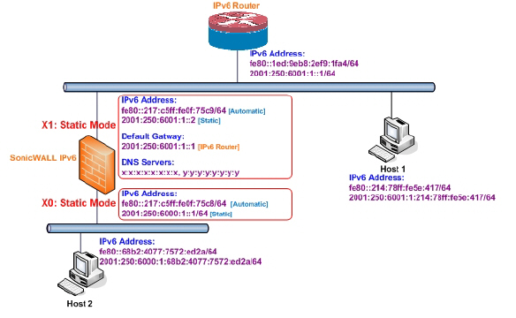
3 types of IPv6 address are possible to assign under this mode:
• Automatic Address
• Autonomous Address
• Static Address
To configure an interface for a static IPv6 address, perform the following steps:
1. Navigate to the Network > Interfaces page.
2. Click on the IPv6 button at the top right corner of the page. IPv6 addresses for the appliance are displayed.
3. Click on the Configure icon for the interface you want to configure an IPv6 address for. The Edit Interface window displays.
Note The zone assignment for interfaces must be configured on the IPv4 addressing page. To modify the zone assignment for an IPv6 interface, click the IPv4 button at the top right of the page, modify the zone for the interface, and then return to the IPv6 interface page.
4. In the IP Assignment pulldown menu, select Static.
5. Enter the IPv6 Address for the interface.
6. Enter the Prefix Length for the address.
7. If this is the primary WAN interface, enter the IPv6 address of the Default Gateway. If this is not the primary WAN interface, any Default Gateway entry will be ignored, so you can leave this as ::. (The double colon is the abbreviation for an empty address, or 0:0:0:0:0:0:0:0.)
8. If this is the primary WAN interface, enter up to three DNS Server IPv6 addresses. Again, if this is not the primary WAN interface, any DNS Server entries will be ignored.
9. Select Enable Router Advertisement to make this an advertising interface that distributes network and prefix information.
10.Select Advertise Subnet Prefix of IPv6 Primary Static Address to add a default prefix into the interface advertising prefix list. This prefix is the subnet prefix of interface IPv6 primary static address. This option will help all hosts on the link stay in the same subnet.
Configuring Advanced IPv6 Interface Options and Multiple IPv6 Addresses
Perform the following steps to modify Advanced IPv6 interface options or to configure multiple static IPv6 addresses.
1. In the Edit Interface window, click on the Advanced tab.
2. Click the Add Address button to configure multiple static IPv6 addresses for the interface.
Note Multiple IPv6 addresses can only be added for an interface that is configured for Static IPv6 address mode. Multiple IPv6 addresses cannot be configured for Auto or DHCPv6 modes.
3. Enter the IPv6 Address for the additional address for the interface.
4. Enter the Prefix Length for the address.
5. Select Advertise Subnet Prefix of IPv6 Primary Static Address to add a default prefix into the interface advertising prefix list. This prefix is the subnet prefix of interface IPv6 primary static address. This option will help all hosts on the link stay in the same subnet.
6. Click OK.
7. The following additional options can be configured on the Advanced tab under the Advanced Settings heading:
• Select Disable all IPv6 Traffic on the Interface to stop the interface from handling all IPv6 traffic. Disabling IPv6 traffic can improve firewall performance for non-IPv6 traffic. If the firewall is deployed in a pure IPv4 environment, SonicWALL recommends enabling this option.
• Select Enable Listening to Router Advertisement to have the firewall receive router advertisement. If disabled, the interface filters all incoming Router Advertisement message, which can enhance security by eliminating the possibility of receiving malicious network parameters (e.g. prefix information or default gateway). This option is not visible for Auto mode. In Auto mode, it is always enabled.
• Select Enable Stateless Address Autoconfiguration to allow autonomous IPv6 addresses to be assigned to this interface. If unchecked, all assigned autonomous IPv6 address will be removed from this interface. This option is not visible for Auto mode. In Auto mode, it is always enabled.
• Enter a numeric value for Duplicate Address Detection Transmits to specify the number of consecutive Neighbor Solicitation messages sent while performing Duplicate Address Detection (DAD) before assigning a tentative address to interface. A value of 0 indicates that DAD is not performed on the interface.
Similar with IPv4 gratuitous ARP, IPv6 node uses Neighbor Solicitation message to detect duplicate IPv6 address on the same link. DAD must be performed on any Unicast address (except Anycast address) before assigning a tentative to an IPv6 interface.
Configuring Router Advertisement Settings
Router Advertisement allows IPv6 routers to advertise DNS recursive server addresses to IPv6 hosts. Router Advertisement-based DNS configuration is a useful, optional alternative in networks where an IPv6 host's address is autoconfigured through IPv6 stateless address autoconfiguration, and where the delays in acquiring server addresses and communicating with the servers are critical. Router Advertisement allows the host to acquire the nearest server addresses on every link. Furthermore, it learns these addresses from the same RA message that provides configuration information for the link, thereby avoiding an additional protocol run. This can be beneficial in some mobile environments, such as with Mobile IPv6. SonicWALL’s implementation of IPv6 is full conformable with RFC 4861 in Router and Prefix Discovery.
Note Router Advertisement can only be enabled when interface is under Static mode.
To configure Router Advertisement for an IPv6 interface, perform the following steps.
1. In the Edit Interface window, click on the Router Advertisement tab.
2. Select the Enable Router Advertisement checkbox to have make this an advertising interface that will distribute network and prefix information.
3. Optionally, you can modify the following Router Advertisement settings:
– Router Adv Interval Range - The time interval allowed between sending unsolicited multicast Router Advertisements from the interface, in seconds.
– Link MTU - The recommended MTU for the interface link. A value of 0 means firewall will not advertise link MTU for the link.
– Reachable Time - The time that a node assumes a neighbor is reachable after having received a reachability confirmation. A value of 0 means this parameter is unspecified by this firewall.
– Retrans Time - The time between retransmitted Neighbor Solicitation messages. A value of 0 means this parameter is unspecified by this firewall.
– Current Hop Limit - The default value that should be placed in the Hop Count field of the IP header for outgoing IP packets. A value of 0 means this parameter is unspecified by this firewall.
– Router Lifetime - The lifetime when firewall is accepted as a default router. A value of 0 means that the router is not a default router.
4. Select the Managed checkbox to set the managed address configuration flag in the Router Advertisement message. If set, it indicates that IPv6 addresses are available via Dynamic Host Configuration Protocol.
5. Select the Other Configuration checkbox to set the Other configuration flag in Router Advertisement message. If set, it indicates that other configuration information is available via Dynamic Host Configuration Protocol.
Configuring Router Advertisement Prefix Settings
1. Click the Add Prefix button to configure an advertising prefix. Advertising prefixes are used for providing hosts with prefixes for on-link determination and Address Autoconfiguration.
2. Enter the Prefix that is to be advertised with the Router Advertisement message.
3. Enter the Valid Lifetime to set the length of time (in minutes) that the prefix is valid for the purpose of on-link determination. A value of “71582789” means the lifetime is infinite.
4. Enter the Preferred Lifetime to set the length of time that addresses generated from the prefix via stateless address autoconfiguration remain preferred. A value of “71582789” means the lifetime is infinite.
5. Optionally click the On-link checkbox to enable the on-link flag in Prefix Information option, which indicates that this prefix can be used for on-link determination.
6. Optionally click the Autonomous checkbox to enable the autonomous address-configuration flag in Prefix Information option, which indicates that this prefix can be used for stateless address configuration.
7. Click OK.
DHCPv6 (DHCP for IPv6) is a client/server protocol that provides stateful address configuration or stateless configuration setting for IPv6 hosts. DHCPv6 client is enabled to learn IPv6 address and network parameters when interface is configured to DHCPv6 mode.
DHCPv6 defines two different configuration modes:
• DHCPv6 stateful mode: DHCPv6 clients require IPv6 address together with other network parameters (e.g. DNS Server, Domain Name, etc.).
• DHCPv6 stateless mode: DHCPv6 client only obtains network parameters other than IPv6 address. Choosing which kind of those modes depends on Managed (M) Address Configuration and Other (O) Configuration flag in the advertised Router Advertisement message:
– M = 0, O = 0: No DHCPv6 infrastructure.
– M = 1, O = 1: IPv6 host use DHCPv6 for both IPv6 address and other network parameter settings.
– M = 0, O = 1: IPv6 host use DHCPv6 only for IPv6 address assignment.
– M = 1, O = 0: IPv6 host use DHCPv6 only for other network parameter settings, which known as DHCPv6 stateless.
The following diagram shows a sample DHCPv6 topology.
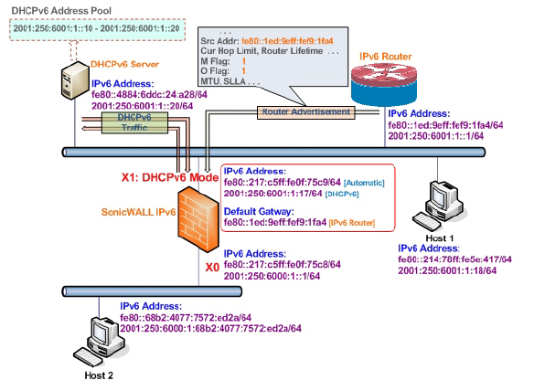
There are three types of IPv6 addresses that can be assign under DHCPv6:
• Automatic Address
• Autonomous Address
• IPv6 Address assigned through DHCPv6 client
To configure an interface for a DHCPv6 address, perform the following steps:
1. Navigate to the Network > Interfaces page.
2. Click on the IPv6 button at the top right corner of the page. IPv6 addresses for the appliance are displayed.
3. Click on the Configure icon for the interface you want to configure an IPv6 address for. The Edit Interface window displays.
4. In the IP Assignment pulldown menu, select DHCPv6.
5. The following options can be configured for IPv6 interfaces configured for DHCPv6 mode:
– Use Rapid Commit Option - If enabled, DHCPv6 client use Rapid Commit Option to use the two message exchange for address assignment.
– Send hints for renewing previous IP on startup - If enabled, DHCPv6 client will try to renew the address assigned before when firewall startup.
6. Set the DHCPv6 Mode for the interface. As required by RFC, DHCPv6 client depends on Router Advertisement message to decide which mode (stateful or stateless) it should choose. This definition will limit user's choice if they want to determine DHCPv6 mode by itself. SonicWALL’s implementation of DHCPv6 defines two different modes to balance the conformance and flexibility:
– Automatic - In this mode, IPv6 interface configures IPv6 addresses using stateless/stateful autoconfiguration in accord with the M and O settings in the most recently received router advertisement message.
– Manual - In Manual mode, DHCPv6 mode is manually configured regardless of any received Router Advertisement. The Only Request Stateless Information option will determine which DHCPv6 mode is used. If this option is unchecked, DHCPv6 client is under stateful mode; if it is checked, DHCPv6 client is under stateless mode and only obtains network parameters.
7. Optionally, select the Only Request Stateless Information checkbox to have DHCPv6 clients only requests network parameter setting from the DHCPv6 server. The IPv6 address is assigned through stateless auto-configuration.
8. Click OK to complete the configuration, or click the Advanced tab to configure Advanced options or click the Protocol tab to view DHCPv6 stateful and stateless configuration information.
Configuring Advanced Settings for an IPv6 Interface
The following options can be configured on the Advanced tab of the IPv6 Edit Interface window:
• Select Disable all IPv6 Traffic on the Interface to stop the interface from handling all IPv6 traffic. Disabling IPv6 traffic can improve firewall performance for non-IPv6 traffic. If the firewall is deployed in a pure IPv4 environment, SonicWALL recommends enabling this option.
• Select Enable Listening to Router Advertisement to have the firewall receive router advertisement. If disabled, the interface filters all incoming Router Advertisement message, which can enhance security by eliminating the possibility of receiving malicious network parameters (e.g. prefix information or default gateway). This option is not visible for Auto mode. In Auto mode, it is always enabled.
• Select Enable Stateless Address Autoconfiguration to allow autonomous IPv6 addresses to be assigned to this interface. If unchecked, all assigned autonomous IPv6 address will be removed from this interface. This option is not visible for Auto mode. In Auto mode, it is always enabled.
• Enter a numeric value for Duplicate Address Detection Transmits to specify the number of consecutive Neighbor Solicitation messages sent while performing Duplicate Address Detection (DAD) before assigning a tentative address to interface. A value of 0 indicates that DAD is not performed on the interface.
Similar with IPv4 gratuitous ARP, IPv6 node uses Neighbor Solicitation message to detect duplicate IPv6 address on the same link. DAD must be performed on any Unicast address (except Anycast address) before assigning a tentative to an IPv6 interface.
DHCPv6 Protocol Tab
When configuring an IPv6 interface in DHCpv6 mode, the Protocol tab displays additional DHCPv6 information.
The following information is displayed on the Protocol tab:
• DHCPv6 State: If the interface is configured for Stateless mode, the DHCPv6 State will be Stateless. If the interface is configured for Stateful mode, the DHCPv6 State will be either Enable or Disabled. When the interface is in Stateful, DHCPv6 mode, mousing over the icon to the left of the DHCPv6 State will display current Router Advertisement information for the interface.
• DHCPv6 Server: The IPv6 address of the DHCPv6 server.
• Stateful Addresses Acquired via DHCPv6: Displays information on any acquired stateful IPv6 addresses.
• DNS Servers: The IPv6 addresses of any DNS Servers.
Auto mode utilities IPv6’s Stateless Address Autoconfiguration to assign IPv6 address. This mode does not require any manual address configuration by the network administrator. The firewall listens to the network and receives prefix information from neighboring routers. The IPv6 Stateless Address Autoconfiguration feature performs all configuration details, such as IPv6 address assignment, address deleting for address conflicting or lifetime expiration, and default gateway selection based on the information collected from on-link router.
Note Auto mode can only be configured for the WAN zone. For security consideration, Auto mode is not available on LAN zone interface.
The following diagram shows a sample topology for IPv6 configured in Auto mode.
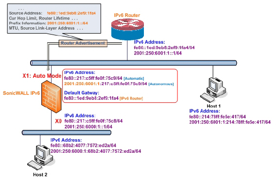
In this mode, 2 types of IPv6 address are possible to assign:
• Automatic Address - The interface default link-local address. It is never timed out and is not able to be edited or deleted.
• Autonomous Address - Assigned from Stateless Address Autoconfiguration. Users can manually delete the address if they do not want to wait for its valid lifetime expires.
To configure an IPv6 interface for Auto mode, perform the following tasks:
1. Navigate to the Network > Interfaces page.
2. Click on the IPv6 button at the top right corner of the page. IPv6 addresses for the appliance are displayed.
3. Click on the Configure icon for the interface you want to configure an IPv6 address for. The Edit Interface window displays.
4. In the IP Assignment pulldown menu, select Auto.
5. Optionally, you can select enter a numeric value for Duplicate Address Detection Transmits on the Advanced tab to specify the number of consecutive Neighbor Solicitation messages sent while performing Duplicate Address Detection (DAD) before assigning a tentative address to interface. A value of 0 indicates that DAD is not performed on the interface.
6. Click OK.
Configuring IPv6 Tunnel Interfaces
![]() For complete information on SonicWALL’s implementation of IPv6, see the Appendix C: IPv6 Appendix.
For complete information on SonicWALL’s implementation of IPv6, see the Appendix C: IPv6 Appendix.
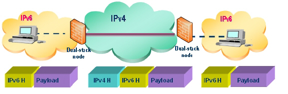
This section describes how to tunnel IPv4 packets through IPv6 networks and IPv6 packets through IPv4 networks. For instance, in order to pass IPv6 packets through the IPv4 network, the IPv6 packet will be encapsulated into an IPv4 packet at the ingress side of a tunnel. When the encapsulated packet arrives at the egress of the tunnel, the IPv4 packet will be de-capsulated.
Tunnels can be either automatic or manually configured. A configured tunnel determines the endpoint addresses by configuration information on the encapsulating node. An automatic tunnel determines the IPv4 endpoints from the address of the embedded IPv6 datagram. IPv4 multicast tunneling determines the endpoints through Neighbor Discovery.
The following diagram depicts an IPv6 to IPv4 tunnel.
The following sections describe IPv6 Tunnel Interface configuration:
• Configuring the 6to4 Auto Tunnel
• Configuring 6to4 Relay for Non-2002 Prefix Access
• Configuring a Manual Ipv6 Tunnel
• Configuring a GRE IPv6 Tunnel
The 6to4 Auto Tunnel is an automatic tunnel: tunnel endpoints are extracted from the encapsulated IPv6 datagram. No manual configuration is necessary.
6to4 tunnels use a prefix of the form “2002:tunnel-IPv4-address::/48” to tunnel IPv6 traffic over IPv4. (for example, if the tunnel’s IPv4 endpoint has the address a01:203, the 6to4 tunnel prefix is “2002:a01:203::1.”) Routers advertise a prefix of the form “2002:[IPv4]:xxxx/64” to IPv6 clients. For complete information, see RFC 3056.
The following diagram shows a sample 6to4 auto tunnel topology.
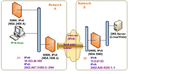
In the example, customers do not need to specify the tunnel endpoint, but only need to enable the 6to4 auto tunnel. All packets with a 2002 prefix will be routed to the tunnel, and the tunnel's IPv4 destination will be extract from the destination IPv6 address.
6to4 tunnels are easy to configure and use. Users must have a global IPv4 address and IPv6 address, which must also have a 2002 prefix. Therefore, in general, user can only access network resource with a 2002 prefix.
Note Only one 6to4 auto tunnel can be configured on the firewall.
To configure the 6to4 tunnel on the firewall, perform the following steps:
1. Navigate to the Network > Interfaces page.
2. Click the Add Interface button.
3. Select the Zone for the 6to4 tunnel interface. This is typically the WAN interface.
4. In the Tunnel Type pulldown menu, select 6to4 Auto Tunnel Interface.
5. By default, the interface Name is set to 6to4AutoTun.
6. Select the Enable IPv6 6to4 Tunnel checkbox.
7. Optionally, you can configure Management login or User Login over the 6to4 tunnel.
8. Click OK.
By default, 6to4 auto tunnel can only access the destination with a 2002 prefix. The 6to4 relay feature can be used to access non-2002 prefix destinations. To enable 6to4 relay, simply create a Route Policy to route all traffic destined for 2003 prefixes over the 6to4 auto tunnel interface, as shown in the following example.
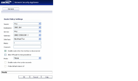
This static route can be added on the 6to4 auto tunnel interface to enable the relay feature, which makes it possible to access the IPv6 destination with non-2002: prefix through 6to4 tunnel. Note that, the gateway must be the IPv6 address with the 2002: prefix.
To configure the 6to4 tunnel on the firewall, perform the following steps:
1. Navigate to the Network > Interfaces page.
2. Click the Add Interface button.
3. Select the Zone for the tunnel interface.
4. In the Tunnel Type pulldown menu, select IPv6 Manual Tunnel Interface.
5. Enter a Name for the tunnel interface.
6. Enter the Remote IPv4 address for the tunnel endpoint.
7. For the Remote IPv6 network select an IPv6 Address object, which can be a group, range, network, or Host.
8. Optionally, you can configure Management login or User Login over the 6to4 tunnel.
9. Click OK.
GRE can be used to tunnel IPv4 and IPv6 traffic over IPv4 or IPv6. GRE tunnels are static tunnels where both endpoints are specified manually. The following diagram shows a sample GRE IPv6 tunnel.
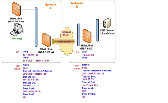
The configuration of a GRE tunnel is similar to a manual tunnel, except GRE Tunnel Interface is selected for the Tunnel Type.