Firewall_qosSettings
Firewall Settings > QoS Mapping
Quality of Service (QoS) refers to a diversity of methods intended to provide predictable network behavior and performance. This sort of predictability is vital to certain types of applications, such as Voice over IP (VoIP), multimedia content, or business-critical applications such as order or credit-card processing. No amount of bandwidth can provide this sort of predictability, because any amount of bandwidth will ultimately be used to its capacity at some point in a network. Only QoS, when configured and implemented correctly, can properly manage traffic, and guarantee the desired levels of network service.
This section contains the following subsections:
Classification
Classification is necessary as a first step so that traffic in need of management can be identified. SonicOS Enhanced uses Access Rules as the interface to classification of traffic. This provides fine controls using combinations of Address Object, Service Object, and Schedule Object elements, allowing for classification criteria as general as all HTTP traffic and as specific as SSH traffic from hostA to serverB on Wednesdays at 2:12am .
SonicOS Enhanced on SonicWALL NSA series appliances has the ability to recognize, map, modify, and generate the industry-standard external CoS designators, DSCP and 802.1p (refer to the “802.1p and DSCP QoS” section ).
Once identified, or classified, it can be managed. Management can be performed internally by SonicOS’ BWM, which is perfectly effective as long as the network is a fully contained autonomous system. Once external or intermediate elements are introduced, such as foreign network infrastructures with unknown configurations, or other hosts contending for bandwidth (e.g. the Internet) the ability to offer guarantees and predictability are diminished. In other words, as long as the endpoints of the network and everything in between are within your management, BWM will work exactly as configured. Once external entities are introduced, the precision and efficacy of BWM configurations can begin to degrade.
But all is not lost. Once SonicOS Enhanced classifies the traffic, it can tag the traffic to communicate this classification to certain external systems that are capable of abiding by CoS tags; thus they too can participate in providing QoS.
|
|
|
Many service providers do not support CoS tags such as 802.1p or DSCP. Also, most
network equipment with standard configurations will not be able to recognize 802.1p tags, and could drop tagged traffic. Although DSCP will not cause compatibility issues, many service providers will simply strip or ignore the DSCP tags, disregarding the code points. If you wish to use 802.1p or DSCP marking on your network or your service provider’s network, you must first establish that these methods are supported. Verify that your internal network equipment can support CoS priority marking, and that it is correctly configured to do so. Check with your service provider – some offer fee-based support for QoS using these CoS methods. |
Marking
Once the traffic has been classified, if it is to be handled by QoS capable external systems (e.g. CoS aware switches or routers as might be available on a premium service provider’s infrastructure, or on a private WAN), it must be tagged so that the external systems can make use of the classification, and provide the correct handling and Per Hop Behaviors (PHB).
Originally, this was attempted at the IP layer (layer 3) with RFC791’s three Precedence bits and RFC1394 ToS (type of service) field, but this was used by a grand total of 17 people throughout history. Its successor, RFC2474 introduced the much more practical and widely used DSCP (Differentiated Services Code Point) which offered up to 64 classifications, as well as user-definable classes. DSCP was further enhanced by RFC2598 (Expedited Forwarding, intended to provide leased-line behaviors) and RFC2697 (Assured Forwarding levels within classes, also known as Gold, Silver, and Bronze levels).
DSCP is a safe marking method for traffic that traverses public networks because there is no risk of incompatibility. At the very worst, a hop along the path might disregard or strip the DSCP tag, but it will rarely mistreat or discard the packet.
The other prevalent method of CoS marking is IEEE 802.1p. 802.1p occurs at the MAC layer (layer 2) and is closely related to IEEE 802.1Q VLAN marking, sharing the same 16-bit field, although it is actually defined in the IEEE 802.1D standard. Unlike DSCP, 802.1p will only work with 802.1p capable equipment, and is not universally interoperable. Additionally, 802.1p, because of its different packet structure, can rarely traverse wide-area networks, even private WANs. Nonetheless, 802.1p is gaining wide support among Voice and Video over IP vendors, so a solution for supporting 802.1p across network boundaries (i.e. WAN links) was introduced in the form of 802.1p to DSCP mapping.
802.1p to DSCP mapping allows 802.1p tags from one LAN to be mapped to DSCP values by SonicOS Enhanced, allowing the packets to safely traverse WAN links. When the packets arrive on the other side of the WAN or VPN, the receiving SonicOS Enhanced appliance can then map the DSCP tags back to 802.1p tags for use on that LAN. Refer to the “802.1p and DSCP QoS” section for more information.
Conditioning
The traffic can be conditioned (or managed) using any of the many policing, queuing, and shaping methods available. SonicOS provides internal conditioning capabilities with its Egress and Ingress Bandwidth Management (BWM), detailed in the “Bandwidth Management” section . SonicOS’s BWM is a perfectly effective solution for fully autonomous private networks with sufficient bandwidth, but can become somewhat less effective as more unknown external network elements and bandwidth contention are introduced. Refer to the “Example Scenario” in the “Example Scenario” section for a description of contention issues.
Site to Site VPN over QoS Capable Networks
If the network path between the two end points is QoS aware, SonicOs can DSCP tag the inner encapsulate packet so that it is interpreted correctly at the other side of the tunnel, and it can also DSCP tag the outer ESP encapsulated packet so that its class can be interpreted and honored by each hop along the transit network. SonicOS can map 802.1p tags created on the internal networks to DSCP tags so that they can safely traverse the transit network. Then, when the packets are received on the other side, the receiving SonicWALL appliance can translate the DSCP tags back to 802.1p tags for interpretation and honoring by that internal network.
Site to Site VPN over Public Networks
SonicOS integrated BWM is very effective in managing traffic between VPN connected networks because ingress and egress traffic can be classified and controlled at both endpoints. If the network between the endpoints is non QoS aware, it regards and treats all VPN ESP equally. Because there is typically no control over these intermediate networks or their paths, it is difficult to fully guarantee QoS, but BWM can still help to provide more predictable behavior.
To provide end-to-end QoS, business-class service providers are increasingly offering traffic conditioning services on their IP networks. These services typically depend on the customer premise equipment to classify and tag the traffic, generally using a standard marking method such as DSCP. SonicOS Enhanced has the ability to DSCP mark traffic after classification, as well as the ability to map 802.1p tags to DSCP tags for external network traversal and CoS preservation. For VPN traffic, SonicOS can DSCP mark not only the internal (payload) packets, but the external (encapsulating) packets as well so that QoS capable service providers can offer QoS even on encrypted VPN traffic.
The actual conditioning method employed by service providers varies from one to the next, but it generally involves a class-based queuing method such as Weighted Fair Queuing for prioritizing traffic, as well a congestion avoidance method, such as tail-drop or Random Early Detection.
802.1p and DSCP QoS
The following sections detail the 802.1p standard and DSCP QoS. These features are supported on SonicWALL NSA platforms.
Enabling 802.1p
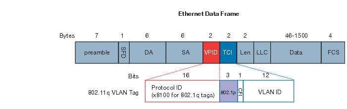
SonicOS Enhanced supports layer 2 and layer 3 CoS methods for broad interoperability with external systems participating in QoS enabled environments. The layer 2 method is the IEEE 802.1p standard wherein 3-bits of an additional 16-bits inserted into the header of the Ethernet frame can be used to designate the priority of the frame, as illustrated in the following figure:
|
|
|
TPID : Tag Protocol Identifier begins at byte 12 (after the 6 byte destination and source fields), is 2 bytes long, and has an Ethertype of 0x8100 for tagged traffic. |
|
|
|
802.1p : The first three bits of the TCI (Tag Control Information – beginning at byte 14, and spanning 2 bytes) define user priority, giving eight (2^3) priority levels. IEEE 802.1p defines the operation for these 3 user priority bits. |
|
|
|
CFI : Canonical Format Indicator is a single-bit flag, always set to zero for Ethernet switches. CFI is used for compatibility reasons between Ethernet networks and Token Ring networks. If a frame received at an Ethernet port has a CFI set to 1, then that frame should not be forwarded as it is to an untagged port. |
|
|
|
VLAN ID : VLAN ID (starts at bit 5 of byte 14) is the identification of the VLAN. It has 12-bits and allows for the identification of 4,096 (2^12) unique VLAN ID’s. Of the 4,096 possible IDs, an ID of 0 is used to identify priority frames, and an ID of 4,095 (FFF) is reserved, so the maximum possible VLAN configurations are 4,094. |
802.1p support begins by enabling 802.1p marking on the interfaces which you wish to have process 802.1p tags. 802.1p can be enabled on any Ethernet interface on any SonicWALL appliance.
The behavior of the 802.1p field within these tags can be controlled by Access Rules. The default 802.1p Access Rule action of None will reset existing 802.1p tags to 0 , unless otherwise configured (see “Managing QoS Marking” section for details).
Enabling 802.1p marking will allow the target interface to recognize incoming 802.1p tags generated by 802.1p capable network devices, and will also allow the target interface to generate 802.1p tags, as controlled by Access Rules. Frames that have 802.1p tags inserted by SonicOS will bear VLAN ID 0.
802.1p tags will only be inserted according to Access Rules, so enabling 802.1p marking on an interface will not, at its default setting, disrupt communications with 802.1p-incapable devices.
802.1p requires the specific support by the networking devices with which you wish to use this method of prioritization. Many voice and video over IP devices provide support for 802.1p, but the feature must be enabled. Check your equipment’s documentation for information on 802.1p support if you are unsure. Similarly, many server and host network cards (NICs) have the ability to support 802.1p, but the feature is usually disabled by default. On Win32 operating systems, you can check for and configure 802.1p settings on the Advanced tab of the Properties page of your network card. If your card supports 802.1p, it will list it as 802.1p QoS , 802.1p Support , QoS Packet Tagging or something similar:
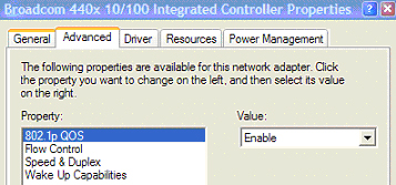
To process 802.1p tags, the feature must be present and enabled on the network interface. The network interface will then be able to generate packets with 802.1p tags, as governed by QoS capable applications. By default, general network communications will not have tags inserted so as to maintain compatibility with 802.1p-incapable devices.
|
|
|
If your network interface does not support 802.1p, it will not be able to process 802.1p
tagged traffic, and will ignore it. Make certain when defining Access Rules to enable 802.1p marking that the target devices are 802.1p capable. It should also be noted that when performing a packet capture (for example, with the diagnostic tool Ethereal) on 802.1p capable devices, some 802.1p capable devices will not show the 802.1q header in the packet capture. Conversely, a packet capture performed on an 802.1p-incapable device will almost invariably show the header, but the host will be unable to process the packet. |
Before moving on to “Managing QoS Marking” section , it is important to introduce ‘DSCP Marking’ because of the potential interdependency between the two marking methods, as well as to explain why the interdependency exists.
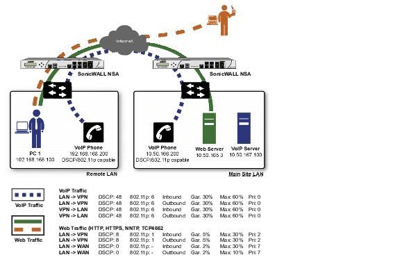
Example Scenario
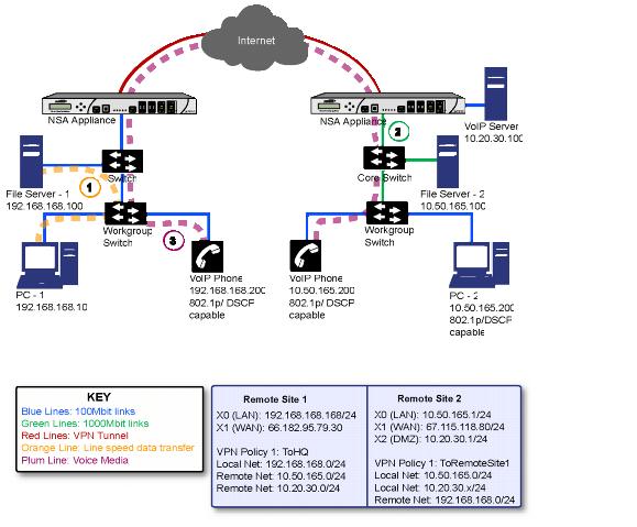
In the scenario above, we have Remote Site 1 connected to ‘Main Site’ by an IPsec VPN. The company uses an internal 802.1p/DSCP capable VoIP phone system, with a private VoIP signaling server hosted at the Main Site. The Main Site has a mixed gigabit and Fast-Ethernet infrastructure, while Remote Site 1 is all Fast Ethernet. Both sites employ 802.1p capable switches for prioritization of internal traffic.
|
|
PC-1 at Remote Site 1 is transferring a 23 terabyte PowerPoint™ presentation to File Server 1, and the 100mbit link between the workgroup switch and the upstream switch is completely saturated. |
|
|
If the link between the Core Switch and the firewall is a VLAN, some switches will include the received 802.1p priority tag, in addition to the DSCP tag, in the packet sent to the firewall; this behavior varies from switch to switch, and is often configurable. |
|
|
If the link between the Core Switch and the firewall is not a VLAN, there is no way for the switch to include the 802.1p priority tag. The 802.1p priority is removed, and the packet (including only the DSCP tag) is forwarded to the firewall. |
When the firewall sent the packet across the VPN/WAN link, it could include the DSCP tag in the packet, but it is not possible to include the 802.1p tag. This would have the effect of losing all prioritization information for the VoIP traffic, because when the packet arrived at the Remote Site, the switch would have no 802.1p MAC layer information with which to prioritize the traffic. The Remote Site switch would treat the VoIP traffic the same as the lower-priority file transfer because of the link saturation, introducing delay—maybe even dropped packets—to the VoIP flow, resulting in call quality degradation.
So how can critical 802.1p priority information from the Main Site LAN persist across the VPN/WAN link to Remote Site LAN? Through the use of QoS Mapping.
QoS Mapping is a feature which converts layer 2 802.1p tags to layer 3 DSCP tags so that they can safely traverse (in mapped form) 802.1p-incapable links; when the packet arrives for delivery to the next 802.1p-capable segment, QoS Mapping converts from DSCP back to 802.1p tags so that layer 2 QoS can be honored.
In our above scenario, the firewall at the Main Site assigns a DSCP tag (e.g. value 48 ) to the VoIP packets, as well as to the encapsulating ESP packets, allowing layer 3 QoS to be applied across the WAN. This assignment can occur either by preserving the existing DSCP tag, or by mapping the value from an 802.1p tag, if present. When the VoIP packets arrive at the other side of the link, the mapping process is reversed by the receiving SonicWALL, mapping the DSCP tag back to an 802.1p tag.
|
|
The receiving SonicWALL at the Remote Site is configured to map the DSCP tag range 48- 55 to 802.1p tag 6. When the packet exits the SonicWALL, it will bear 802.1p tag 6. The Switch will recognize it as voice traffic, and will prioritize it over the file-transfer, guaranteeing QoS even in the event of link saturation. |
DSCP Marking
DSCP (Differentiated Services Code Point) marking uses 6-bits of the 8-bit ToS field in the IP Header to provide up to 64 classes (or code points) for traffic. Since DSCP is a layer 3 marking method, there is no concern about compatibility as there is with 802.1p marking. Devices that do not support DSCP will simply ignore the tags, or at worst, they will reset the tag value to 0.
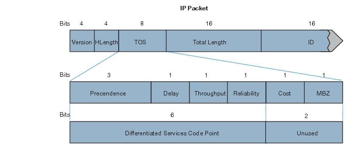
The above diagram depicts an IP packet, with a close-up on the ToS portion of the header. The ToS bits were originally used for Precedence and ToS (delay, throughput, reliability, and cost) settings, but were later repurposed by RFC2474 for the more versatile DSCP settings.
The following table shows the commonly used code points, as well as their mapping to the legacy Precedence and ToS settings.
|
3 (Flash
– 011)
|
|||
|
5 (CRITIC/ECP
– 101)
|
|||
DSCP marking can be performed on traffic to/from any interface and to/from any zone type, without exception. DSCP marking is controlled by Access Rules, from the QoS tab, and can be used in conjunction with 802.1p marking, as well as with SonicOS’ internal bandwidth management.
DSCP Marking and Mixed VPN Traffic
Among their many security measures and characteristics, IPsec VPNs employ anti-replay mechanisms based upon monotonically incrementing sequence numbers added to the ESP header. Packets with duplicate sequence numbers are dropped, as are packets that do not adhere to sequence criteria. One such criterion governs the handling of out-of-order packets. SonicOS Enhanced provides a replay window of 64 packets, i.e. if an ESP packet for a Security Association (SA) is delayed by more than 64 packets, the packet will be dropped.
This should be considered when using DSCP marking to provide layer 3 QoS to traffic traversing a VPN. If you have a VPN tunnel that is transporting a diversity of traffic, some that is being DSCP tagged high priority (e.g. VoIP), and some that is DSCP tagged low-priority, or untagged/best-effort (e.g. FTP), your service provider will prioritize the handling and delivery of the high-priority ESP packets over the best-effort ESP packets. Under certain traffic conditions, this can result in the best-effort packets being delayed for more than 64 packets, causing them to be dropped by the receiving SonicWALL’s anti-replay defenses.
If symptoms of such a scenario emerge (e.g. excessive retransmissions of low-priority traffic), it is recommended that you create a separate VPN policy for the high-priority and low-priority classes of traffic. This is most easily accomplished by placing the high-priority hosts (e.g. the VoIP network) on their own subnet.
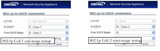
Configure for 802.1p CoS 4 – Controlled load
If you want to change the inbound mapping of DSCP tag 15 from its default 802.1p mapping of 1 to an 802.1p mapping of 2 , it would have to be done in two steps because mapping ranges cannot overlap. Attempting to assign an overlapping mapping will give the error DSCP range already exists or overlaps with another range. First, you will have to remove 15 from its current end-range mapping to 802.1p CoS 1 (changing the end-range mapping of 802.1p CoS 1 to DSCP 14 ), then you can assign DSCP 15 to the start-range mapping on 802.1p CoS 2 .
QoS Mapping
The primary objective of QoS Mapping is to allow 802.1p tags to persist across non-802.1p compliant links (e.g. WAN links) by mapping them to corresponding DSCP tags before sending across the WAN link, and then mapping from DSCP back to 802.1p upon arriving at the other side:
|
|
|
Mapping will not occur until you assign Map as an action of the QoS tab of an Access Rule. The mapping table only defines the correspondence that will be employed by an Access Rule’s Map action. |
For example, according to the default table, an 802.1p tag with a value of 2 will be outbound mapped to a DSCP value of 16 , while a DSCP tag of 43 will be inbound mapped to an 802.1 value of 5 .
Each of these mappings can be reconfigured. If you wanted to change the outbound mapping of 802.1p tag 4 from its default DSCP value of 32 to a DSCP value of 43 , you can click the Configure icon for 4 – Controlled load and select the new To DSCP value from the drop-down box:
You can restore the default mappings by clicking the Reset QoS Settings button.
Managing QoS Marking
QoS marking is configured from the QoS tab of Access Rules under the Firewall > Access Rules page of the management interface. Both 802.1p and DSCP marking as managed by SonicOS Enhanced Access Rules provide 4 actions: None, Preserve, Explicit, and Map. The default action for DSCP is Preserve and the default action for 802.1p is None .
The following table describes the behavior of each action on both methods of marking:
|
When packets match
ing this class of traffic (as defined by the Access Rule) are sent out the egress interface, no 802.1p tag will be added.
|
If the target interface for this class
of traffic is a VLAN subinterface, the 802.1p portion of the 802.1q tag will be explicitly set to 0. If this class of traffic is destined for a VLAN and is using 802.1p for prioritization, a specific Access Rule using the Preserve
, Explicit
, or Map
action should be defined for this class of traffic.
|
||
|
Existing DSCP tag value will be pre
served.
|
|||
|
An explicit 802.1p tag
value can be assigned (0-7) from a drop-down menu that will be presented.
|
An explicit DSCP tag value can be
assigned (0-63) from a drop-down menu that will be presented.
|
||
|
The mapping setting
defined in the Fire
wall Settings > QoS
Mapping
page will be used to map from a DSCP tag to an 802.1p tag .
|
The mapping setting defined in the Firewall Settings > QoS Mapping
page will be used to map from an 802.1 tag to a DSCP tag. An additional checkbox will be presented to Allow
802.1p Marking to override DSCP
values.
Selecting this checkbox will assert the mapped 802.1p value over any DSCP value that might have been set by the client. This is useful to override clients setting their own DSCP CoS values.
|
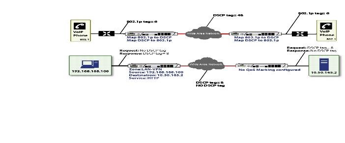
For example, refer to the following figure which provides a bi-directional DSCP tag action.
HTTP access from a Web-browser on 192.168.168.100 to the Web server on 10.50.165.2 will result in the tagging of the inner (payload) packet and the outer (encapsulating ESP) packets with a DSCP value of 8. When the packets emerge from the other end of the tunnel, and are delivered to 10.50.165.2, they will bear a DSCP tag of 8. When 10.50.165.2 sends response packets back across the tunnel to 192.168.168.100 (beginning with the very first SYN/ACK packet) the Access Rule will tag the response packets delivered to 192.168.168.100 with a DSCP value of 8.
This behavior applies to all four QoS action settings for both DSCP and 802.1p marking.
One practical application for this behavior would be configuring an 802.1p marking rule for traffic destined for the VPN zone. Although 802.1p tags cannot be sent across the VPN, reply packets coming back across the VPN can be 802.1p tagged on egress from the tunnel. This requires that 802.1p tagging is active of the physical egress interface, and that the [Zone] > VPN Access Rule has an 802.1p marking action other than None.
After ensuring 802.1p compatibility with your relevant network devices, and enabling 802.1p marking on applicable SonicWALL interfaces, you can begin configuring Access Rules to manage 802.1p tags.
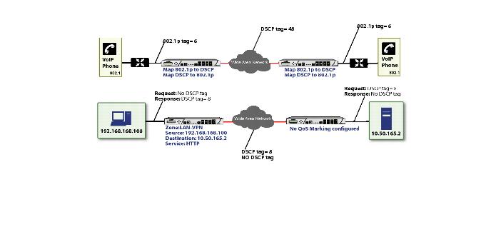
Referring to the following figure, the Remote Site 1 network could have two Access Rules configured as follows:
|
Allow 802.1p Marking to override DSCP values |
||
The first Access Rule (governing LAN>VPN ) would have the following effects:
|
|
|
VoIP traffic (as defined by the Service Group) from LAN Primary Subnet destined to be sent across the VPN to Main Site Subnets would be evaluated for both DSCP and 802.1p tags. |
|
|
|
The combination of setting both DSCP and 802.1p marking actions to Map is described in the table earlier in the “Managing QoS Marking” section . |
|
|
|
Sent traffic containing only an 802.1p tag (e.g. CoS = 6) would have the VPN-bound inner (payload) packet DSCP tagged with a value of 48. The outer (ESP) packet would also be tagged with a value of 48. |
|
|
|
Assuming returned traffic has been DSCP tagged (CoS = 48) by the SonicWALL at the Main Site, the return traffic will be 802.1p tagged with CoS = 6 on egress. |
|
|
|
Sent traffic containing only a DSCP tag (e.g. CoS = 48) would have the DSCP value preserved on both inner and outer packets. |
|
|
|
Assuming returned traffic has been DSCP tagged (CoS = 48) by the SonicWALL at the Main Site, the return traffic will be 802.1p tagged with CoS = 6 on egress. |
|
|
|
Sent traffic containing only both an 802.1p tag (e.g. CoS = 6) and a DSCP tag (e.g. CoS = 63) would give precedence to the 802.1p tag, and would be mapped accordingly. The VPN-bound inner (payload) packet DSCP tagged with a value of 48. The outer (ESP) packet would also be tagged with a value of 48. |
Assuming returned traffic has been DSCP tagged (CoS = 48) by the SonicWALL at the Main Site, the return traffic will be 802.1p tagged with CoS = 6 on egress.
To examine the effects of the second Access Rule (VPN>LAN), we’ll look at the Access Rules configured at the Main Site.
|
Allow 802.1p Marking to override DSCP values |
||
VoIP traffic (as defined by the Service Group) arriving from Remote Site 1 Subnets across the VPN destined to LAN Subnets on the LAN zone at the Main Site would hit the Access Rule for inbound VoIP calls. Traffic arriving at the VPN zone will not have any 802.1p tags, only DSCP tags.
|
|
|
Traffic exiting the tunnel containing a DSCP tag (e.g. CoS = 48) would have the DSCP value preserved. Before the packet is delivered to the destination on the LAN, it will also be 802.1p tagged according to the QoS Mapping settings (e.g. CoS = 6) by the SonicWALL at the Main Site. |
|
|
|
Assuming returned traffic has been DSCP tagged (e.g. CoS = 48) by the VoIP phone receiving the call at the Main Site, the return traffic will have the DSCP tag preserved on both the inner and outer packet sent back across the VPN. |
Bandwidth Management
Although bandwidth management (BWM) is a fully integrated QoS service, wherein classification and shaping is performed on the single SonicWALL appliance, effectively eliminating the dependency on external systems and thus obviating the need for marking, it is possible to concurrently configure BWM and QoS (layer 2 and/or layer 3 marking) settings on a single Access Rule. This allows those external systems to benefit from the classification performed on the SonicWALL even after it has already shaped the traffic. For details on how to configure BWM, see “Methods of Configuring Bandwidth Management” section .
Outbound Bandwidth Management
The available bandwidth on a WAN link is tracked by means of adjusting a link credit (token) pool for each packet sent. Providing that the link has not yet reached a point of saturation, the prioritized queues are deemed eligible for processing.
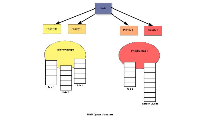
Like CBQ, SonicOS BWM is based on a class structure, where traffic queues are classified according to Access Rules—for example SSH, Telnet, or HTTP—and then scheduled according to their prescribed priority. Each participating Access Rule is assigned three values: Guaranteed bandwidth, Maximum bandwidth, and Bandwidth priority. Scheduling prioritization is achieved by assignment to one of eight priority queues, starting at 0 (zero) for the highest priority, and descending to 7 (seven) for the lowest priority. The resulting queuing hierarchy can be best thought of as a node tree structure that is always one level deep, where all nodes are leaf nodes, containing no children.
Queue processing utilizes a time division scheme of approximately 1/256th of a second per time-slice. Within a time-slice, evaluation begins with priority 0 queues, and on a packet-by-packet basis transmission eligibility is determined by measuring the packet’s length against the queue credit pool. If sufficient credit is available, the packet is transmitted and the queue and link credit pools are decremented accordingly. As long as packets remain in the queue, and as long as Guaranteed link and queue credits are available, packets from that queue will continue to be processed. When Guaranteed queue credits are depleted, the next queue in that priority queue is processed. The same process is repeated for the remaining priority queues, and upon completing priority 7 begins again with priority 0.
The scheduling for excess bandwidth is strict priority, with per-packet round-robin within each priority. In other words, if there is excess bandwidth for a given time-slice all the queues within that priority would take turns sending packets until the excess was depleted, and then processing would move to the next priority.
This credit-based method obviates the need for CBQ’s concept of overlimit , and addresses one of the largest problems of traditional CBQ, namely, bursty behavior (which can easily flood downstream devices and links). This more prudent approach spares SonicOS the wasted CPU cycles that would normally be incurred by the need for re-transmission due to the saturation of downstream devices, as well as avoiding other congestive and degrading behaviors such as TCP slow-start (see Sally Floyd’s Limited Slow-Start for TCP with Large Congestion Windows ), and Global Synchronization (as described in RFC 2884 ):
Queue management algorithms traditionally manage the length of packet queues in the router by dropping packets only when the buffer overflows. A maximum length for each queue is configured. The router will accept packets till this maximum size is exceeded, at which point it will drop incoming packets. New packets are accepted when buffer space allows. This technique is known as Tail Drop. This method has served the Internet well for years, but has the several drawbacks. Since all arriving packets (from all flows) are dropped when the buffer overflows, this interacts badly with the congestion control mechanism of TCP. A cycle is formed with a burst of drops after the maximum queue size is exceeded, followed by a period of underutilization at the router as end systems back off. End systems then increase their windows simultaneously up to a point where a burst of drops happens again. This phenomenon is called Global Synchronization. It leads to poor link utilization and lower overall throughput. Another problem with Tail Drop is that a single connection or a few flows could monopolize the queue space, in some circumstances. This results in a lock out phenomenon leading to synchronization or other timing effects. Lastly, one of the major drawbacks of Tail Drop is that queues remain full for long periods of time. One of the major goals of queue management is to reduce the steady state queue size.
Algorithm for Outbound Bandwidth Management
Each packet through the SonicWALL is initially classified as either a Real Time or a Firewall packet. Firewall packets are user-generated packets that always pass through the BWM module. Real time packets are usually firewall generated packets that are not processed by the BWM module, and are implicitly given the highest priority. Real Time (firewall generated) packets include:
Outbound BWM Packet Processing Path
Guaranteed Bandwidth Processing
This algorithm depicts how all the policies use up the GBW.
|
|
If that packet length is less than or equal to the class credit, transmit the packet and deduct the length from class credit and link credit. |
|
|
Choose the next packet from queue and repeat step c until class credit is lesser or rule queue is empty. |
Maximum Bandwidth Processing
This algorithm depicts how the unutilized link BW is used up by the policies. We start with the highest priority and transmit packets from all the rule queues in a round robin fashion until link credit is exhausted or all queues are empty. Then we move on to the next lowest priority and repeat the same.
|
|
Check if the length of a packet from the rule queue is below class credit as well as link credit. |
|
|
Choose the next rule queue and repeat steps c through f until link credit gets exhausted or this priority has all its queues empty. |
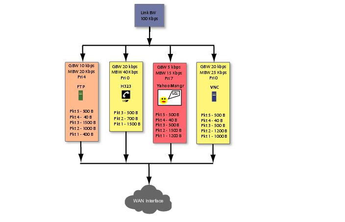
Example of Outbound BWM
The above diagram shows 4 policies are configured for OBWM with a link capacity of 100 Kbps. This means that the link capacity is 12800 Bytes/sec. Below table gives the BWM values for each rule in Bytes per second.
|
|
We move on to the next rule queue in this list which is for H323. Pkt1 of 1500B is sent out and link credit becomes 10900 and class credit for H323 becomes 1060. Pkt2 is also sent from queue hence link credit = 10200 and class credit = 360. Pkt3 is not sent since there is not enough class credit. The remaining class credit is carried over to the next time slice. |
|
|
From VNC queue, Pkt1 and Pkt2 are sent out leaving link credit = 8000 and class credit = 360. Class credit is carried over. |
|
|
Since all the queues have been processed for GBW we now move onto use up the left over link credit of 8000. |
|
|
Move to the next queue in this priority which is VNC queue. Pkt3 of 500B is sent out leaving link credit = 7000B and class max = 140 (MBW-GBW - 500). |
|
|
Move to the next queue in this priority. Since H323 queue is empty already we move to the next queue which is VNC again. |
|
|
From VNC queue Pkt4 of 40B is sent out leaving link credit = 6960 and class max = 100. Pkt5 of 500B is not sent since class max is not enough. |
|
|
Now we move onto next lower priority queue. Since priorities 1 through 3 are empty we choose priority 4 which has the rule queue for FTP. Pkt2 of 1000B is sent which leaves with link credit = 6000 and class max = 280. Since there are no other queues in this priority, FTP queue is processed again. But since class max is not enough for Pkt3 of 1500B it is not sent. |
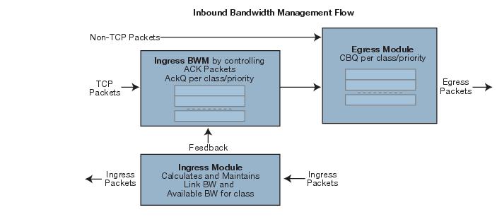
Inbound Bandwidth Management
Inbound BWM can be used to shape inbound TCP and UDP traffic. TCP’s intrinsic flow control behavior is used to manage ingress bandwidth. To manage inbound UDP traffic, CBQ is used by the ingress module to queue the incoming packets. TCP rate is inherently controlled by the rate of receipt of ACKs; i.e. TCP sends out packets out on the network at the same rate as it receives ACKs. For IBWM, the sending rate of a TCP source will be reduced by controlling the rate of ACKs to the source. By delaying an ACK to the source, round-trip time (RTT) for the flow is increased, thus reducing the source’s sending rate.
An ingress module monitors and records the ingress rate for each traffic class. It also monitors the egress ACKs and queues them if the ingress rate has to be reduced. According to ingress BW availability and average rate, the ACKs will be released.
Algorithm for Inbound Bandwidth Management
IBWM maintains eight priority queues, where each priority has one rule that has IBWM enabled. The IBWM pool is processed from the highest to lowest priority further shaping the traffic. IBWM employs three key algorithms:
Ingress Rate Update
This algorithm processes each packet from the WAN and updates the ingress rate of the class to which it belongs. It also marks the traffic class if it has over utilized the link.
|
|
Add the packet length to the sum of packet lengths received so far in the current time slice. Deduct the minimum of (GBW, packet length) from link’s credit. |
|
|
If the packet length is greater than the link’s credit, mark the link as well as the class to be over utilized. |
Egress ACK monitor
This algorithm depicts how the egress ACKs are monitored and processed.
|
|
If class or interface is marked as over utilizing, queue the packet in the appropriate ingress rule queue. |
Process ACKs
This algorithm is used to update the BW parameters per class according to the amount of BW usage in the previous time slice. Amount of BW usage is given by the total number of bytes received for the class in the previous time slice. The algorithm is also used to process the packets from the ingress module queues according to the available credit for the class.
Credit-Based Processing
A class will be in debt when its BW usage is more than the GBW for a particular time slice. All the egress ACKs for the class are then queued until the debt is reduced to zero. At each successive time slice, debt is deducted by GBW and if link BW is left, (MBW – GBW) is also deducted.
Compute BW usage in the previous time slice:
|
|
If the BW usage is more than the class credit, record the difference as debt. If link BW is left over, deduct (MBW - GBW) from debt. |
|
|
|
If the class is in debt, deduct GBW from debt and also from link’s credit, indicating that the class has already used up its GBW for the current time slice. |
|
|
|
If class is not in debt and there are packets arriving for this class, accumulate link credit; i.e. add GBW to credit at each time slice. |
|
|
If remaining credit is greater than or equal to average rate, process the ACK packet and deduct average rate from remaining credit. |
Example of Inbound Bandwidth Management
Consider a class with GBW = 5 Kbps, MBW = 10 Kbps and Link BW = 100 Kbps. In terms of bytes per second we have GBW=640, excess BW = (MBW - GBW) = 640 and link BW = 12800.
In row 2a, an ACK packet is received that needs to be sent to the TCP source on the WAN zone. Sending this ACK immediately would have caused the TCP source to send more packets immediately. By queuing the ACK and sending it only after the class credit reaches the average rate, we have reduced the TCP’s sending rate; i.e. by doing this we have slowed down the ingress rate.
Glossary
|
|
|
802.1p – IEEE 802.1p is a Layer 2 (MAC layer) Class of Service mechanism that tags packets by using 3 priority bits (for a total of 8 priority levels) within the additional 16-bits of an 802.1q header. 802.1p processing requires compatible equipment for tag generation, recognition and processing, and should only be employed on compatible networks. 802.1p is supported on SonicWALL NSA platforms. |
|
|
|
Bandwidth Management (BWM) – Refers to any of a variety of algorithms or methods used to shape traffic or police traffic. Shaping often refers to the management of outbound traffic, while policing often refers to the management of inbound traffic (also known as admission control). There are many different methods of bandwidth management, including various queuing and discarding techniques, each with their own design strengths. SonicWALL employs a Token Based Class Based Queuing method for inbound and outbound BWM, as well as a discard mechanism for certain types of inbound traffic. |
|
|
|
Class of Service (CoS) – A designator or identifier, such as a layer 2 or layer 3 tag, that is applied to traffic after classification. CoS information will be used by the Quality of Service (QoS) system to differentiate between the classes of traffic on the network, and to provide special handling (e.g. prioritized queuing, low latency, etc.) as defined by the QoS system administrator. |
|
|
|
Classification – The act of identifying (or differentiating) certain types (or classes) of traffic. Within the context of QoS, this is performed for the sake of providing customized handling, typically prioritization or de-prioritization, based on the traffic’s sensitivity to delay, latency, or packet loss. Classification within SonicOS Enhanced uses Access Rules, and can occur based on any or all of the following elements: source zone, destination zone, source address object, destination address object, service object, schedule object. |
|
|
|
Code Point – A value that is marked (or tagged) into the DSCP portion of an IP packet by a host or by an intermediate network device. There are currently 64 Code Points available, from 0 to 63, used to define the ascending prioritized class of the tagged traffic. |
|
|
|
Conditioning – A broad term used to describe a plurality of methods of providing Quality of Service to network traffic, including but not limited to discarding, queuing, policing, and shaping. |
|
|
|
DiffServ – Differentiated Services. A standard for differentiating between different types or classes of traffic on an IP network for the purpose of providing tailored handling to the traffic based on its requirements. DiffServ primarily depends upon Code Point values marked in the ToS header of an IP packet to differentiate between different classes of traffic. DiffServ service levels are executed on a Per Hop Basis at each router (or other DiffServ enabled network device) through which the marked traffic passes. DiffServ Service levels currently include at a minimum Default , Assured Forwarding , and Expedited Forwarding . DiffServ is supported on SonicWALL NSA platforms. Refer to the “DSCP Marking” section for more information. |
|
|
|
Discarding – A congestion avoidance mechanism that is employed by QoS systems in an attempt to predict when congestion might occur on a network, and to prevent the congestion by dropping over-limit traffic. Discarding can also be thought of as a queue management algorithm, since it attempts to avoid situations of full queues. Advanced discard mechanisms will abide by CoS markings so as to avoid dropping sensitive traffic. Common methods are: |
|
|
|
Tail Drop – An indiscriminate method of dealing with a full queue wherein the last packets into the queue are dropped, regardless of their CoS marking. |
|
|
|
Random Early Detection (RED) – RED monitors the status of queues to try to anticipate when a queue is about to become full. It then randomly discards packets in a staggered fashion to help minimize the potential of Global Synchronization. Basic implementations of RED, like Tail Drop, do not consider CoS markings. |
|
|
|
Weighted Random Early Detection (WRED) – An implementation of RED that factors DSCP markings into its discard decision process. |
|
|
|
DSCP – (Differentiate Services Code Points) – The repurposing of the ToS field of an IP header as described by RFC2747. DSCP uses 64 Code Point values to enable DiffServ (Differentiated Services). By marking traffic according to its class, each packet can be treated appropriately at every hop along the network. |
|
|
|
Global Synchronization – A potential side effect of discarding, the congestion avoidance method designed to deal with full queues. Global Synchronization occurs when multiple TCP flows through a congested link are dropped at the same time (as can occur in Tail Drop). When the native TCP slow-start mechanism commences with near simultaneity for each of these flows, the flows will again flood the link. This leads to cyclical waves of congestion and under-utilization. |
|
|
|
Guaranteed Bandwidth – A declared percentage of the total available bandwidth on an interface which will always be granted to a certain class of traffic. Applicable to both inbound and outbound BWM. The total Guaranteed Bandwidth across all BWM rules cannot exceed 100% of the total available bandwidth. SonicOS Enhanced 5.0 and higher enhances the Bandwidth Management feature to provide rate limiting functionality. You can now create traffic policies that specify maximum rates for Layer 2, 3, or 4 network traffic. This enables bandwidth management in cases where the primary WAN link fails over to a secondary connection that cannot handle as much traffic. The Guaranteed Bandwidth can also be set to 0%. |
|
|
|
Inbound (Ingress or IBWM) – The ability to shape the rate at which traffic enters a particular interface. For TCP traffic, actual shaping can occur where the rate of the ingress flow can be adjusted by delaying egress acknowledgements (ACKs) causing the sender to slow its rate. For UDP traffic, a discard mechanism is used since UDP has no native feedback controls. |
|
|
|
IntServ – Integrated Services, as defined by RFC1633. An alternative CoS system to DiffServ, IntServ differs fundamentally from DiffServ in that it has each device request (or reserve) its network requirements before it sends its traffic. This requires that each hop on the network be IntServ aware, and it also requires each hop to maintain state information for every flow. IntServ is not supported by SonicOS. The most common implementation of IntServ is RSVP. |
|
|
|
Maximum Bandwidth – A declared percentage of the total available bandwidth on an interface defining the maximum bandwidth to be allowed to a certain class of traffic. Applicable to both inbound and outbound BWM. Used as a throttling mechanism to specify a bandwidth rate limit. The Bandwidth Management feature is enhanced to provide rate limiting functionality. You can now create traffic policies that specify maximum rates for Layer 2, 3, or 4 network traffic. This enables bandwidth management in cases where the primary WAN link fails over to a secondary connection that cannot handle as much traffic.The Maximum Bandwidth can be set to 0%, which will prevent all traffic. |
|
|
|
Outbound (Egress or OBWM) – Conditioning the rate at which traffic is sent out an interface. Outbound BWM uses a credit (or token) based queuing system with eight priority queues to service different types of traffic, as classified by Access Rules. |
|
|
|
Priority – An additional dimension used in the classification of traffic. SonicOS uses eight priority (0 = realtime, 7 = lowest) to comprise the queue structure used for BWM. Queues are serviced in the order of their priority. |
|
|
|
Mapping – Mapping, with regard to SonicOS’ implementation of QoS, is the practice of converting layer 2 CoS tags (802.1p) to layer 3 CoS tags (DSCP) and back again for the purpose as preserving the 802.1p tags across network links that do not support 802.1p tagging. The map correspondence is fully user-definable, and the act of mapping is controlled by Access Rules. Mapping is supported on SonicWALL NSA platforms. |
|
|
|
Marking – Also known as tagging or coloring – The act of applying layer 2 (802.1p) or layer 3 (DSCP) information to a packet for the purpose of differentiation, so that it can be properly classified (recognized) and prioritized by network devices along the path to its destination. Marking is supported on SonicWALL NSA platforms. |
|
|
|
MPLS - Multi Protocol Label Switching. A term that comes up frequently in the area of QoS, but which is natively unsupported by most customer premise IP networking devices, including SonicWALL appliances. MPLS is a carrier-class network service that attempts to enhance the IP network experience by adding the concept connection-oriented paths (Label Switch Paths – LSPs) along the network. When a packet leaves a customer premise network, it is tagged by a Label Edge Router (LER) so that the label can be used to determine the LSP. The MPLS tag itself resides between layer 2 and layer 3, imparting upon MPLS characteristics of both network layers. MPLS is becoming quite popular for VPNs, offering both layer 2 and layer 3 VPN services, but remains interoperable with existing IPsec VPN implementation. MPLS is also very well known for its QoS capabilities, and interoperates well with conventional DSCP marking. |
|
|
|
Per Hop Behavior (PHB) – The handling that will be applied to a packet by each DiffServ capable router it traverses, based upon the DSCP classification of the packet. The behavior can be among such actions as discard, re-mark (re-classify), best-effort, assured forwarding, or expedited forwarding. |
|
|
|
Policing – A facility of traffic conditioning that attempts to control the rate of traffic into or out of a network link. Policing methods range from indiscriminate packet discarding to algorithmic shaping, to various queuing disciplines. |
|
|
|
Queuing – To effectively make use of a link’s available bandwidth, queues are commonly employed to sort and separately manage traffic after it has been classified. Queues are then managed using a variety of methods and algorithms to ensure that the higher priority queues always have room to receive more traffic, and that they can be serviced (de-queued or processed) before lower priority queues. Some common queue disciplines include: |
|
|
|
FIFO – First In First Out. A very simple, undiscriminating queue where the first packet in is the first packet to be processed. |
|
|
|
Class Based Queuing (CBQ) – A queuing discipline that takes into account the CoS of a packet, ensuring that higher priority traffic is treated preferentially. |
|
|
|
Weighted Fair Queuing (WFQ) – A discipline that attempts to service queues using a simple formula based upon the packets’ IP precedence and the total number of flows. WFQ has a tendency to become imbalanced when there is a disproportionately large number of high-priority flows to be serviced, often having the opposite of the desired effect. |
|
|
|
Token Based CBQ – An enhancement to CBQ that employs a token, or a credit-based system that helps to smooth or normalize link utilization, avoiding burstiness as well as under-utilization. Employed by SonicOS’ BWM. |
|
|
|
RSVP – Resource Reservation Protocol. An IntServ signaling protocol employed by some applications where the anticipated need for network behavior (e.g. delay and bandwidth) is requested so that it can be reserved along the network path. Setting up this Reservation Path requires that each hop along the way be RSVP capable, and that each agrees to reserve the requested resources. This system of QoS is comparatively resource intensive, since it requires each hop to maintain state on existing flows. Although IntServ’s RSVP is quite different from DiffServ’s DSCP, the two can interoperate. RSVP is not supported by SonicOS. |
|
|
|
Shaping – An attempt by a QoS system to modify the rate of traffic flow, usually by employing some feedback mechanism to the sender. The most common example of this is TCP rate manipulation, where acknowledgements (ACKs) sent back to a TCP sender are queued and delayed so as to increase the calculated round-trip time (RTT), leveraging the inherent behavior of TCP to force the sender to slow the rate at which it sends data. |
|
|
|
Type of Service (ToS) – A field within the IP header wherein CoS information can be specified. Historically used, albeit somewhat rarely, in conjunction with IP precedence bits to define CoS. The ToS field is now rather commonly used by DiffServ’s code point values. |