Hardware_Failover_haMonitoring
High Availability > Monitoring
The following sections describe High Availability monitoring:
Active/Idle High Availability Monitoring
On the High Availability > Monitoring page, you can configure both physical and logical interface monitoring. By enabling physical interface monitoring, you enable link detection for the designated HA interfaces. The link is sensed at the physical layer to determine link viability. Logical monitoring involves configuring the SonicWALL to monitor a reliable device on one or more of the connected networks. Failure to periodically communicate with the device by the Active unit in the HA Pair will trigger a failover to the Idle unit. If neither unit in the HA Pair can connect to the device, no action will be taken.
The Primary and Secondary IP addresses configured on this page are used for multiple purposes:
As independent management addresses for each unit (supported on all physical interfaces)
To allow synchronization of licenses between the Idle unit and the SonicWALL licensing server
As the source IP addresses for the probe pings sent out during logical monitoring
Configuring unique management IP addresses for both units in the HA Pair allows you to log in to each unit independently for management purposes. Note that non-management traffic is ignored if it is sent to one of these IP addresses. The Primary and Secondary SonicWALL SuperMassives’ unique LAN IP addresses cannot act as an active gateway; all systems connected to the internal LAN will need to use the virtual LAN IP address as their gateway.
The management IP address of the Secondary/Idle unit is used to allow license synchronization with the SonicWALL licensing server, which handles licensing on a per-appliance basis (not per-HA Pair). Even if the Secondary unit was already registered on MySonicWALL before creating the HA association, you must use the link on the System > Licenses page to connect to the SonicWALL server while accessing the Secondary appliance through its management IP address.
When using logical monitoring, the HA Pair will ping the specified Logical Probe IP address target from the Primary as well as from the Secondary SonicWALL. The IP address set in the Primary IP Address or Secondary IP Address field is used as the source IP address for the ping. If both units can successfully ping the target, no failover occurs. If both cannot successfully ping the target, no failover occurs, as the SonicWALLs will assume that the problem is with the target, and not the SonicWALLs. But, if one SonicWALL can ping the target but the other SonicWALL cannot, the HA Pair will failover to the SonicWALL that can ping the target.
The configuration tasks on the High Availability > Monitoring page are performed on the Primary unit and then are automatically synchronized to the Secondary.
To set the independent LAN management IP addresses and configure physical and/or logical interface monitoring, perform the following steps:
Login as an administrator to the SonicOS user interface on the Primary SonicWALL.
In the left navigation pane, navigate to High Availability > Monitoring.
Click the Configure icon for an interface on the LAN, such as X0.
To enable link detection between the designated HA interfaces on the Primary and Secondary units, leave the Enable Physical Interface Monitoring checkbox selected.
In the Primary IP Address field, enter the unique LAN management IP address of the Primary unit.
In the Secondary IP Address field, enter the unique LAN management IP address of the Secondary unit.
Select the Allow Management on Primary/Secondary IP Address checkbox. When this option is enabled for an interface, a green icon appears in the interface’s Management column in the Monitoring Settings table on the High Availability > Monitoring page. Management is only allowed on an interface when this option is enabled.
In the Logical Probe IP Address field, enter the IP address of a downstream device on the LAN network that should be monitored for connectivity. Typically, this should be a downstream router or server. (If probing is desired on the WAN side, an upstream device should be used.) The Primary and Secondary appliances will regularly ping this probe IP address. If both can successfully ping the target, no failover occurs. If neither can successfully ping the target, no failover occurs, because it is assumed that the problem is with the target, and not the SonicWALL appliances. But, if one appliance can ping the target but the other appliance cannot, failover will occur to the appliance that can ping the target.
The Primary IP Address and Secondary IP Address fields must be configured with independent IP addresses on a LAN interface, such as X0, (or a WAN interface, such as X1, for probing on the WAN) to allow logical probing to function correctly.
Optionally, to manually specify the virtual MAC address for the interface, select Override Virtual MAC and enter the MAC address in the field. The format for the MAC address is six pairs of hexadecimal numbers separated by colons, such as A1:B2:C3:d4:e5:f6. Care must be taken when choosing the Virtual MAC address to prevent configuration errors.
When the Enable Virtual MAC checkbox is selected on the High Availability> Advanced page, the SonicOS firmware automatically generates a Virtual MAC address for all interfaces. Allowing the SonicOS firmware to generate the Virtual MAC address eliminates the possibility of configuration errors and ensures the uniqueness of the Virtual MAC address, which prevents possible conflicts.
Click OK.
To configure monitoring on any of the other interfaces, repeat the above steps.
When finished with all High Availability configuration, click Accept. All settings will be synchronized to the Idle unit automatically.
Active/Active High Availability Monitoring
The configuration tasks on the High Availability > Monitoring page are performed on the Primary unit and then are automatically synchronized to the Secondary. These settings only affect the HA pair in the Cluster Node that is selected at the top of the page.
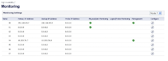
Figure 51:16 High Availability > Monitoring Page
To set the independent LAN management IP addresses and configure physical and/or logical interface monitoring, perform the following steps:
Login as an administrator to the SonicOS management interface on the Master Node.
In the left navigation pane, navigate to High Availability > Monitoring.
At the top right side of the page, select the node to configure from the drop-down list.
Click the Configure icon for an interface on the LAN, such as X0.
To enable link detection between the designated HA interfaces on the Primary and Secondary units, leave the Enable Physical Interface Monitoring checkbox selected.

In the Primary IP Address field, enter the unique LAN management IP address of the Primary unit.
In the Secondary IP Address field, enter the unique LAN management IP address of the Secondary unit.
Select the Allow Management on Primary/Secondary IP Address checkbox. When this option is enabled for an interface, a green icon appears in the interface’s Management column in the Monitoring Settings table on the High Availability > Monitoring page. Management is only allowed on an interface when this option is enabled.
In the Logical Probe IP Address field, enter the IP address of a downstream device on the LAN network that should be monitored for connectivity. Typically, this should be a downstream router or server. (If probing is desired on the WAN side, an upstream device should be used.) The Primary and Secondary appliances will regularly ping this probe IP address. If both can successfully ping the target, no failover occurs. If neither can successfully ping the target, no failover occurs, because it is assumed that the problem is with the target, and not the SonicWALL appliances. But, if one appliance can ping the target and the other appliance cannot, failover will occur to the appliance that can ping the target.
The Primary IP Address and Secondary IP Address fields must be configured with independent IP addresses on a LAN interface, such as X0, (or a WAN interface, such as X1, for probing on the WAN) to allow logical probing to function correctly.
Click OK.
To configure monitoring on any of the other interfaces, repeat the above steps.
When finished with all High Availability monitoring configuration for the selected Cluster Node, click Apply. Then select a different Cluster Node and repeat the configuration steps and then click Apply.
For additional information on verifying the configuration, see Viewing FIB routes in the GUI.
Verifying Active/Active Clustering Configuration
This section describes several methods of verifying the correct configuration of Active/Active Clustering and Active/Active DPI. See the following:
Comparing CPU Activity on Appliances in a Cluster
On the active firewall of the Master node, the System > Diagnostics page with Multi-Core Monitor selected shows the activity of all appliances in the Active/Active cluster. Figure 51:17 displays the Multi-Core Monitor on an Active/Active cluster with Active/Active DPI enabled. This configuration utilizes all units in the cluster for the highest possible performance.
Figure 51:17 System > Diagnostics Page for Multi-Core Monitor
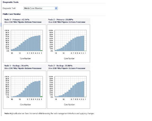
When Active/Active DPI is enabled on a Stateful HA pair, you can observe a change in CPU utilization on appliances in the HA pair. CPU activity goes down on the active unit, and goes up on the idle unit.
When viewing the Multi-Core Monitor on an active unit in the cluster, all firewalls in the cluster are displayed. However, if you log into the individual IP address of an idle unit in the cluster, the Multi-Core Monitor page only displays the core usage for the two firewalls in that particular HA pair.
Note To see the core usage for all firewalls in the cluster, SonicWALL recommends viewing the Multi-Core Monitor page on the active unit of the Master node.
Verifying Settings in the High Availability > Status Page
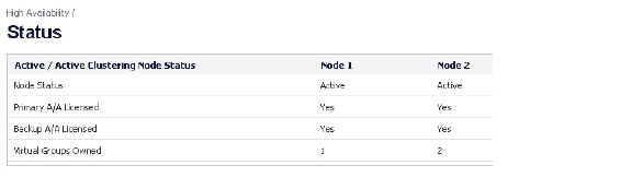
The High Availability > Status page provides status for the entire Active/Active cluster and for each Cluster Node in the deployment.
The Active/Active Clustering node status is displayed at the top of the page, and shows values for the following settings:
Node Status – Active or Idle for each node in the cluster
Primary A/A Licensed – Yes or No for each node in the cluster
Secondary A/A Licensed – Yes or No for each node in the cluster
Virtual Groups Owned – Displays the Virtual Group number owned by each node in the cluster. You can check these values to determine the owner status after a failover.
The Active/Active Clustering Node Status table is shown in Figure 51:19.
Figure 51:18 Active/Active Clustering Node Status Table
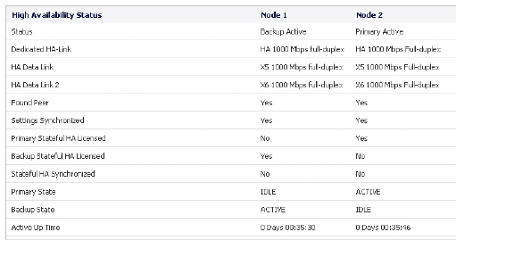
In the lower section of the page, shown in Figure 51:19, the High Availability Status table displays the HA settings and status for each node in the cluster.
Figure 51:19 High Availability Status Table
You can tell that Active/Active DPI is correctly configured on your Stateful HA pair by generating a Tech Support Report on the System > Diagnostics page. The following configuration parameters should appear with their correct values in the Tech Support Report:
Enable Active/Active DPI
Active/Active DPI Interface configuration
To generate a TSR for this purpose:
Log into the Stateful HA pair using the shared IP address.
Navigate to the System > Diagnostics page.
Under Tech Support Report, click Download Report.

Responses, or actions, are always sent out from the active unit of the Stateful HA pair running Active/Active DPI when DPI matches are found in network traffic. Note that this does not indicate that all the processing was performed on the active unit.
Deep Packet Inspection discovers network traffic that matches IPS signatures, virus attachments, App Rules policies, and other malware. When a match is made, SonicOS performs an action such as dropping the packet or resetting the TCP connection.
Some DPI match actions inject additional TCP packets into the existing stream. For example, when an SMTP session carries a virus attachment, SonicOS sends the SMTP client a “552” error response code, with a message saying “the email attachment contains a virus.” A TCP reset follows the error response code and the connection is terminated.
These additional TCP packets are generated as a result of the DPI processing on the idle firewall. The generated packets are sent to the active firewall over the Active/Active DPI Interface, and are sent out from the active firewall as if the processing occurred on the active firewall. This ensures seamless operation and it appears as if the DPI processing was done on the active firewall.
If Active/Active DPI is enabled and DPI processing on the idle firewall results in a DPI match action as described above, then the action is logged on the active unit of the Stateful HA pair, rather than on the idle unit where the match action was detected. This does not indicate that all the processing was performed on the active unit.
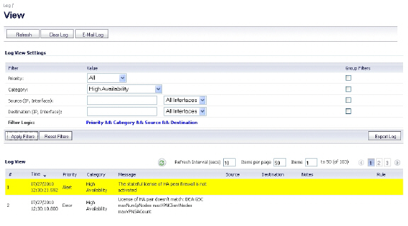
High Availability related log events can be viewed in the Log > View page.
Figure 51:20 Log > View Page Showing High Availability Events
Configuring VPN and NAT with Active/Active Clustering
Extra considerations must be taken when configuring the following features in an Active/Active Clustering environment:
VPN Configuration with Active/Active Clustering
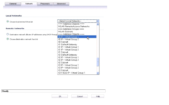
VPN policy configuration requires association with a Virtual Group when running in Active/Active Clustering mode. In the VPN Policy window, both the Network and Advanced tabs have new configuration options for creating this association.
On the Network tab, Virtual Group address objects are available for the Choose local network from list option, as shown in Figure 51:21. These Virtual Group address objects are created by SonicOS when virtual IP addresses are added, and are deleted when the virtual IP is deleted.
Figure 51:21 VPN Policy Window - Local Network Options
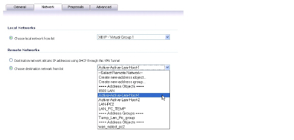
If creating a VPN Policy for a remote network, Virtual Group address objects may also be available. For example, Figure 51:22 shows one with the custom name Active-Active-Lan-Host-1.
Figure 51:22 VPN Policy Window - Remote Network Options
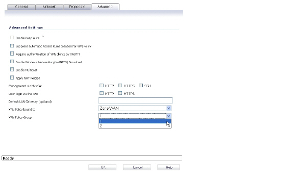
On the Advanced tab, you can select the Virtual Group number for the VPN Policy Group setting. The default is Virtual Group 1. See Figure 51:23.
Figure 51:23 VPN Policy Window - Advanced
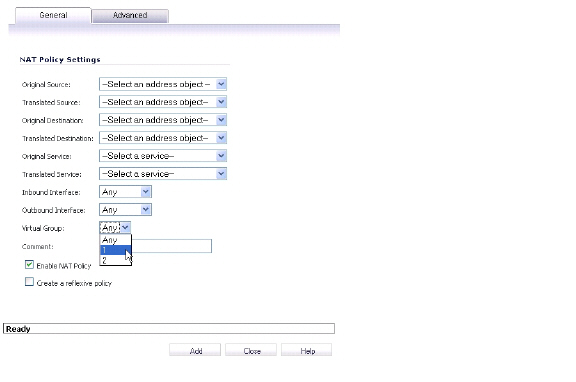
NAT Policy Configuring with Active/Active Clustering
When running in Active/Active Clustering mode, NAT policy configuration includes Virtual Group settings. Default NAT policies are created by SonicOS when virtual IP addresses are added, and are deleted when the virtual IP is deleted. You can specify a Virtual Group or select Any when creating custom NAT policies. Figure 51:24 shows the NAT policy automatically created for Virtual Group 2 on interface X1.
Figure 51:24 Default NAT Policy
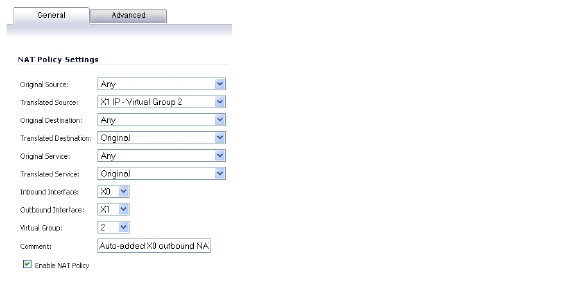
Figure 51:25 shows the selections for the Virtual Group option in the Add NAT Policy window when creating a custom NAT policy.
Figure 51:25 Custom NAT Policy
Registering and Associating Appliances on MySonicWALL
To use Active/Active Clustering, you must register all SonicWALL appliances in the cluster on MySonicWALL. The two appliances in each HA pair must also be associated as HA Primary and HA Secondary on MySonicWALL. That is, associate the two appliances in the HA pair for Cluster Node 1, then associate the appliances in the HA pair for Cluster Node 2, and so on for any other Cluster Nodes. Note that the Secondary appliance of the HA pair is referred to as the HA Secondary unit on MySonicWALL.
After the appliances are associated as an HA pair, they can share licenses. In addition to High Availability licenses, this includes the SonicOS license, the Support subscription, and the security services licenses. The only licenses that are not shareable are for consulting services, such as the SonicWALL GMS Preventive Maintenance Service.
It is not required that the Primary and Secondary appliances have the same security services enabled. The security services settings will be automatically updated as part of the initial synchronization of settings. License synchronization is used so that the Secondary appliance can maintain the same level of network protection provided before the failover.
MySonicWALL provides several methods of associating the two appliances. You can start by registering a new appliance, and then choosing an already-registered unit to associate it with. Or, you can associate two units that are both already registered. You can also start the process by selecting a registered unit and adding a new appliance with which to associate it.
For detailed procedures describing the association process on MySonicWALL, see the High Availability chapter in the SonicOS Administrator’s Guide, available on:
http://www.sonicwall.com/us/Support.html
Note Even if you first register your appliances on MySonicWALL, you must individually register both the Primary and the Secondary appliances from the SonicOS management interface while logged into the individual management IP address of each appliance. This allows the Secondary unit to synchronize with the SonicWALL license server and share licenses with the associated Primary appliance. When Internet access is restricted, you can manually apply the shared licenses to both appliances.
For information about configuring and using the individual management IP address of each appliance, see About High Availability Monitoring and High Availability > Monitoring.
Licensing High Availability Features
Active/Active Clustering, Stateful High Availability, and Active/Active DPI licenses are included on registered SonicWALL SuperMassives. Because Active/Active Clustering is supported only on E-Class appliances, you do not need to purchase any additional licenses to use these High Availability features.
Note Active/Active Clustering and Stateful High Availability licenses must be activated on each appliance, either by registering the unit on MySonicWALL from the SonicOS management interface, or by applying the license keyset to each unit if Internet access is not available.
You can view system licenses on the System > Licenses page of the management interface. This page also provides a way to log into MySonicWALL.
When the SonicWALL SuperMassives in the Active/Active cluster have Internet access, each appliance in the cluster must be individually registered from the SonicOS management interface while the administrator is logged into the individual management IP address of each appliance. This allows the Secondary units to synchronize with the SonicWALL licensing server and share licenses with the associated Primary appliances in each HA pair.
There is also a way to synchronize licenses for an HA pair whose appliances do not have Internet access. When live communication with SonicWALL's licensing server is not permitted due to network policy, you can use license keysets to manually apply security services licenses to your appliances. When you register a SonicWALL SuperMassive on MySonicWALL, a license keyset is generated for the appliance. If you add a new security service license, the keyset is updated. However, until you apply the licenses to the appliance, it cannot perform the licensed services.
Note In a High Availability deployment without Internet connectivity, you must apply the license keyset to both of the appliances in the HA pair.
You can use one of the following procedures to apply licenses to an appliance:
Activating Licenses from the SonicOS User Interface
Follow the procedure in this section to activate licenses from within the SonicOS user interface. Perform the procedure for each of the appliances in a High Availability Pair while logged into its individual LAN management IP address.
See High Availability > Monitoring for information about configuring the individual IP addresses.
Log in to the SonicOS user interface using the individual LAN management IP address for the appliance.
On the System > Licenses page, under Manage Security Services Online, click the link for To Activate, Upgrade or Renew services, click here.
In the Licenses > License Management page, type your MySonicWALL user name and password into the text boxes.
Click Submit.
On the Systems > Licenses page under Manage Security Services Online, verify the services listed in the Security Services Summary table.
Repeat this procedure for the other appliance in the HA pair.
Copying the License Keyset from MySonicWALL
You can follow the procedure in this section to view the license keyset on MySonicWALL and copy it to the SonicWALL SuperMassive. Perform the procedure for each of the appliances in a High Availability Pair while logged into its individual LAN management IP address.
See High Availability > Monitoring for information about configuring the individual IP addresses.
Login to your MySonicWALL account at <https://www.mysonicwall.com/>.
In the left navigation pane, click My Products.
On the My Products page, under Registered Products, scroll down to find the appliance to which you want to copy the license keyset. Click the product name or serial number.
On the Service Management page, click View License Keyset.
On the License Keyset page, use your mouse to highlight all the characters in the text box.
To copy the license keyset to the clipboard, press Ctrl+C.
Log in to the SonicOS user interface by using the individual LAN management IP address.
On the Systems > Licenses page under Manual Upgrade, press Ctrl+V to paste the license keyset into the Or enter keyset text box.
Click Submit.
Repeat this procedure for the other appliance in the HA pair.
Physically Connecting Your Appliances
High Availability requires additional physical connections among the affected SonicWALL appliances. This section describes the physical connections needed for Active/Active Clustering and Active/Active DPI.
Connecting the HA Ports for Active/Active Clustering
For Active/Active Clustering, you must physically connect the designated HA ports of all units in the Active/Active cluster to the same Layer 2 network.
SonicWALL recommends connecting all designated HA ports to the same Layer 2 switch. You can use a dedicated switch or simply use some ports on an existing switch in your internal network. All of these switch ports must be configured to allow Layer 2 traffic to flow freely amongst them.
In the case of a two-unit Active/Active cluster deployment, where the two Cluster Nodes each have only a single appliance, you can connect the HA ports directly to each other using a cross-over cable. No switch is necessary in this case.
The SonicWALL Virtual Router Redundancy Protocol (SVRRP) uses this HA port connection to send Cluster Node management and monitoring state messages. SVRRP management messages are initiated on the Master Node, and monitoring information is communicated from every appliance in the cluster.
The HA port connection is also used to synchronize configuration from the Master Node to the other Cluster Nodes in the deployment. This includes firmware or signature upgrades, policies for VPN and NAT, and other configuration.
Connecting the Active/Active DPI Interfaces for Active/Active DPI
For Active/Active DPI, you must physically connect at least one additional interface, called the Active/Active DPI Interface, between the two appliances in each HA pair, or Cluster Node. The connected interfaces must be the same number on both appliances, and must initially appear as unused, unassigned interfaces in the Network > Interfaces page. For example, you could connect X5 on the Primary unit to X5 on the Secondary if X5 is an unassigned interface. After enabling Active/Active DPI, the connected interface will have a Zone assignment of HA Data-Link.
Certain packet flows on the active unit are selected and offloaded to the idle unit on the Active/Active DPI Interface. DPI is performed on the idle unit and then the results are returned to the active unit over the same interface.
Optionally, for port redundancy with Active/Active DPI, you can physically connect a second Active/Active DPI Interface between the two appliances in each HA pair. This interface will take over transferring data between the two units during Active/Active DPI processing if the first Active/Active DPI Interface has a fault.
To connect the Active/Active DPI Interfaces for Active/Active DPI:
Decide which interface to use for the additional connection between the appliances in the HA pair. The same interface must be selected on each appliance.
In the SonicOS management interface, navigate to the Network > Interfaces page and ensure that the Zone is Unassigned for the intended Active/Active DPI Interface.
Using a standard Ethernet cable, connect the two interfaces directly to each other.
Optionally, for port redundancy with Active/Active DPI, physically connect a second Active/Active DPI Interface between the two appliances in each HA pair.
Connecting the LAN and WAN Interfaces in a High Availability Deployment
In any High Availability deployment, you must physically connect the LAN and WAN ports of all units to the appropriate switches.
A WAN connection to the Internet is useful for registering your appliances on MySonicWALL and for synchronizing licensing information. Unless live communication with SonicWALL's licensing server is not permitted due to network policy, the WAN (X1) interface should be connected before registration and licensing are performed.
Connecting Redundant Port Interfaces
You can assign an unused physical interface as a redundant port to a configured physical interface called the “primary interface”. On each Cluster Node, each primary and redundant port pair must be physically connected to the same switch, or preferably, to redundant switches in the network.
Note Because all Cluster Nodes share the same configuration, each node must have the same redundant ports configured and connected to the same switch(es).
Example: Active/Active Clustering – Four-Unit Deployment
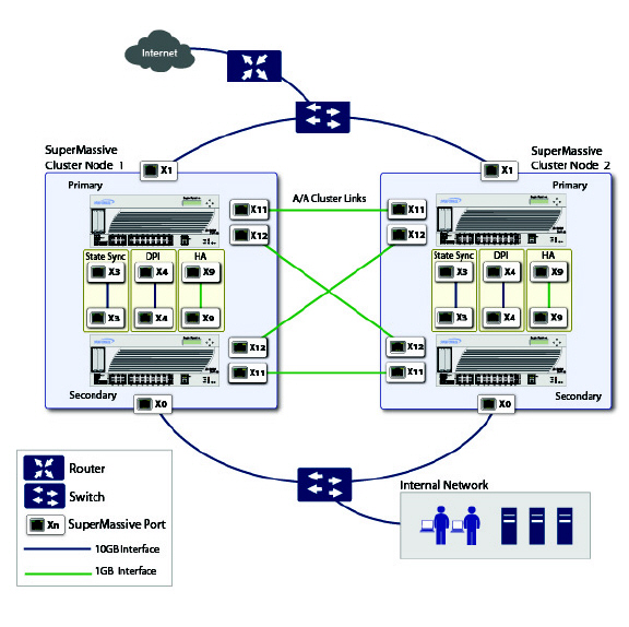
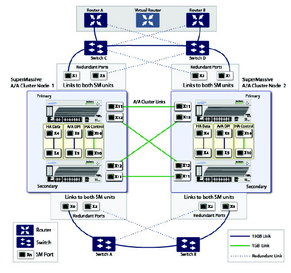
Figure 51:26 shows a diagram of a four-unit cluster. Each Cluster Node contains one HA pair. The designated HA ports of all four appliances are connected to a Layer 2 switch. These ports are used for Cluster Node management and monitoring state messages sent over SVRRP, and for configuration synchronization. The two units in each HA pair are also connected to each other using another interface (shown as the “Xn” interface). This is the Active/Active DPI Interface necessary for Active/Active DPI. With Active/Active DPI enabled, certain packets are offloaded to the idle unit of the HA pair for DPI processing.
Figure 51:26 Active/Active Four-Unit Cluster
For more information about physically connecting redundant ports and redundant switches, see the Active/Active Clustering Full Mesh Deployment Technote.
Example: Active/Active Clustering – Two-Unit Deployment
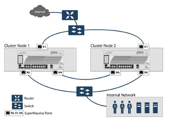
Figure 51:27 shows a diagram of a two-unit cluster. In a two-unit cluster, HA pairs are not used. Instead, each Cluster Node contains a single appliance. The designated HA ports on the two appliances are connected directly to each other using a cross-over cable. The SonicWALL Virtual Router Redundancy Protocol (SVRRP) uses this HA port connection to send Cluster Node management and monitoring state messages. SVRRP management messages are initiated on the Master Node, and monitoring information is communicated from every appliance in the cluster. The HA port connection is also used for configuration synchronization between Cluster Nodes.
Figure 51:27 Active/Active Two-Unit Cluster
Configuring Network DHCP and Interface Settings
When Active/Active Clustering is enabled, the SonicOS internal DHCP server is turned off and cannot be enabled. Networks needing a DHCP server can use an external DHCP server. The SonicOS DHCP server should be disabled in the management interface before enabling Active/Active Clustering, and all DHCP server lease scopes deleted.
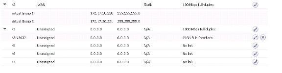
On the Network > Interfaces page, you can configure additional virtual IP addresses for interfaces in a Virtual Group, and redundant ports for interfaces.
For information about performing these tasks, see the following sections:
Disabling the SonicOS DHCP Server
To disable the SonicOS DHCP server and delete all DHCP server lease scopes, perform the following steps:
Login to the Primary unit of the Cluster Node and navigate to the Network > DHCP Server page.
Clear the Enable DHCP Server checkbox.
Under DHCP Server Lease Scopes, select the checkbox at the top left corner of the table heading to select all lease scopes in the table.
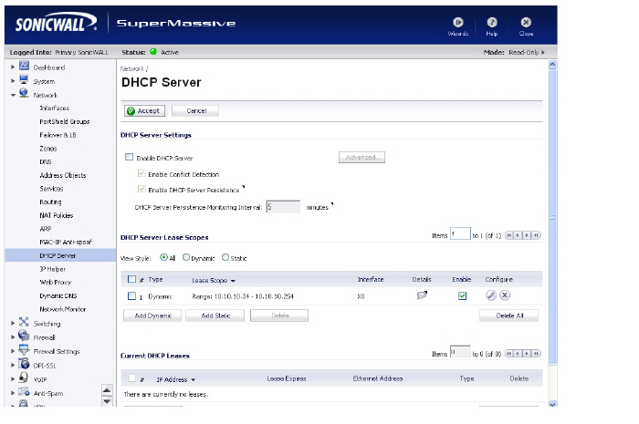
Click the Delete All button.
Click OK in the confirmation dialog box.
Click Accept at the top of the Network > DHCP Server page.
Configuring Virtual IP Addresses
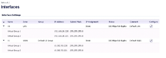
When Active/Active Clustering is enabled for the first time, the configured IP addresses for the interfaces on that firewall are automatically converted to virtual IP addresses for Virtual Group 1. Thus, Virtual Group 1 will include virtual IP addresses for X0, X1, and any other interfaces which are configured and assigned to a zone.
Active/Active Clustering requires additional configuration of virtual IP addresses for additional Virtual Groups. You can assign multiple virtual IP addresses to each interface, one per Virtual Group. Each additional virtual IP address is associated with one of the other Virtual Groups in the cluster. Each interface can have up to a maximum of four virtual IP addresses. VLAN interfaces can also have up to four virtual IP addresses.
Note A packet cannot be forwarded on an interface if a virtual IP address is not configured on it for the Virtual Group handling that traffic flow.
To configure a virtual IP address on an interface:
Login to the Primary unit of the Cluster Node and navigate to the Network > Interfaces page.
In the Interface Settings table, click the configure icon for the interface you want to configure.
In the Edit Interface window, type the virtual IP address into the IP Address (Virtual Group X) field, where ‘X’ is the virtual group number.
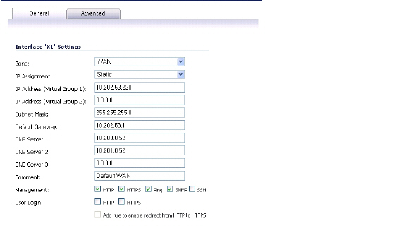
Note The new virtual IP address must be in the same subnet as any existing virtual IP address for that interface.
Click OK. The configured virtual IP address appears in the Interface Settings table.
Redundant ports can be used along with Active/Active Clustering. You can assign an unused physical interface as a redundant port to a configured physical interface called the “primary interface”. If there is a physical link failure on the primary interface, the redundant interface can continue processing traffic without any interruption. One advantage of this feature is that in case of a physical link failure, there is no need to do a device failover.
You can configure a redundant port on the Advanced tab of the Edit Interface window. The Redundant Port field is only available when Active/Active Clustering is enabled.
Note Because all Cluster Nodes share the same configuration, each node must have the same redundant ports configured and connected to the same switch(es).
For information about physically connecting redundant ports and redundant switches, see the Active/Active Clustering Full Mesh Deployment Technote.
To configure a redundant port for an interface:
Login to the Primary unit of the Cluster Node and navigate to the Network > Interfaces page.
In the Interface Settings table, click the configure icon for the primary interface for which you want to create a redundant port.
For example, click the configure icon for X2.
In the Edit Interface window, click the Advanced tab.
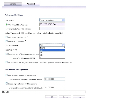
In the Redundant Port field, select the redundant port from the drop-down list. Only unused interfaces are available for selection.
For example, select X4 for the redundant port.
Click OK.
The selected interface will be greyed-out in the Interface Settings table. A note indicates that it is a redundant Port and lists the primary interface. The interface also appears in the Redundant Port field in the Edit Interface window of the primary port.
Note The primary and redundant ports must be physically connected to the same switch, or preferably, to redundant switches in the network.
On each Cluster Node, replicate the redundant physical connections using the same interface numbers for primary and redundant ports. All Cluster Nodes share the same configuration as the Master node.
Active/Active Clustering Full-Mesh Overview
Active/Active Clustering Full-Mesh configuration is an enhancement to the Active/Active Clustering configuration option and prevents any single point of failure in the network. All firewall and other network devices are partnered for complete redundancy. Full-Mesh ensures that there is no single point of failure in your deployment, whether it is a device (firewall/switch/router) or a link. Every device is wired twice to the connected devices. Active/Active Clustering with Full-Mesh provides the highest level of availability possible with high performance.
Note The routers in the firewall’s upstream network should be pre-configured for Virtual Router Redundancy Protocol (VRRP).
Benefits of Active/Active Clustering Full Mesh
The following are key benefits to this deployment configuration:
No Single Point of Failure in the Core Network: In an Active/Active Clustering Full-Mesh deployment, there is no single point of failure in the entire core network, not just for the firewalls. An alternative path for a traffic flow is always available in case there are simultaneous failures of switch, router, firewall on a path, thus providing the highest levels of availability.
Port Redundancy: Active/Active Clustering Full-Mesh utilizes port redundancy in addition to HA redundancy within each Cluster Node, and node level redundancy within the cluster. With port redundancy, a backup link will take over in a transparent manner if the primary port fails. This prevents the need for device level failover.
Configuring Active/Active Clustering Full Mesh
This section describes the procedure for setting up an Active/Active Cluster Full-Mesh deployment. It describes a 4 unit Active/Active Clustering Full-Mesh setup. We will go over the following aspects of the deployment:
Cabling for Active/Active Full Mesh
Configuring the Active/Active Cluster Firewalls
Testing for No Single Point of Failure
The deployments described are examples. Your actual deployment might differ based on the following factors:
Topology/design of your network and the types of network devices you use (switches, routers, load balancers, etc)
Level of availability desired
Resource constraints
Figure 51:28 Active/Active Four-Unit Cluster Full Mesh
Cabling for Active/Active Full Mesh
This procedure describes the cabling for the deployment illustrated in the above diagram.
To physically connect your network devices for a full-mesh deployment, perform the following steps:
Connect all the HA links of all the firewalls into a port-based-VLAN on Switch E.
In the setup described above, X2 is the redundant port of X0. Connect the cables as follows for the X0, X2 ports:
Connect CN2-Primary Firewall’s X0 to Switch A and X2 to Switch B.
Connect CN2-Backup Firewall’s X0 to Switch A and X2 to Switch B.
Connect CN2-Primary Firewall’s X0 to Switch B and X2 to Switch A.
Connect CN2-Backup Firewall’s X0 to Switch B and X2 to Switch A.
On Switch A and Switch B:
Configure all the Switch ports connected to the X0,X2 interfaces to be in the same port-based VLAN.
Enable Spanning Tree, but also enable Port Fast (or equivalent command) on the ports connected to the firewalls.
In the setup described above, X3 is the redundant port of X1. Connect the cables as follows for the X1, X3 ports:
Connect CN2-Primary Firewall’s X1 to Switch C and X3 to Switch D.
Connect CN2-Backup Firewall’s X1 to Switch C and X3 to Switch D.
Connect CN2-Primary Firewall’s X1 to Switch D and X3 to Switch C.
Connect CN2-Backup Firewall’s X1 to Switch D and X3 to Switch C.
On Switch C and Switch D:
Configure all the Switch ports connected to the X1,X3 interfaces to be in the same port-based VLAN.
Enable Spanning Tree, but also enable Port Fast (or equivalent command) on the ports connected to the firewalls.
Cable Switch A and Switch B together.
Cable Switch C and Switch D together.
If the Router A and Router B have redundant port support, then connect the Routers to Switches in the same way as we connected the Firewall ports to Switches. That is, connect the primary port on Router A to Switch C and the backup port on Router A to Switch D. Connect the ports in the same way for Router B.
If the Routers do not have redundant port support, but have switching support then you create two ports in the same VLAN on Router A and assign an IP address to the VLAN instead of the port. Then connect one port to Switch C and the other port to Switch D. Do a similar configuration for Router B. (This is the setup shown in the diagram).
In the setup described above, we also use Active/Active DPI along with Active/Active Clustering. Ports X6 and X7 are the two HA data ports for redundancy and load-sharing of offloaded traffic from Active to Idle firewalls. Perform the following cabling (X6,X7 ports and cabling have not been shown in the above diagram for brevity):
Connect X6 of CN1-Primary to X6 of CN1-Backup with a Cross-over cable.
Connect X7 of CN1-Primary to X7 of CN1-Backup with a Cross-over cable.
Connect X6 of CN2-Primary to X6 of CN2-Backup with a Cross-over cable.
Connect X7 of CN2-Primary to X7 of CN2-Backup with a Cross-over cable.
Configuring Active/Active Cluster Firewalls
This section describes the steps to configure the Active/Active Cluster firewalls.
Shut down all firewalls except the CN1-Primary unit.
On the High Availability > Settings page:
Choose Active/Active Clustering mode.
Enter the Cluster Node serial numbers.
Select CN1 as Owner for Virtual Group 1 and Standby for Virtual Group 2.
Select CN2 as Owner for Virtual Group 2 and Standby for Virtual Group 1.
Enable Stateful Synchronization.
Enable Active/Active DPI with X6 and X7 as the two HA data ports.
Click Submit.
On the Network > Interfaces page:
Add the Virtual Group (VG) IP addresses for both the X0 and X1 interfaces.
Add the redundant port configuration (X2 as redundant port of X0, X3 as redundant port of X1).
On the High Availability > Monitoring page, add the monitoring/management IP addresses either on X0 or X1 for each unit in the cluster.
Turn on all the other firewalls. A complete synchronization of the configuration is made from the CN1-Primary to all other firewalls.
Login to each firewall unit using the dedicated monitoring/management address and do the following:
Register the firewall on MySonicWALL.
Synchronize the licenses with MySonicWALL.
Testing for No Point of Failure
After the above deployment is connected and configured, CN1 will own Virtual Group1 (VG1), and CN2 will own Virtual Group 2 (VG2).
Configure the VG1 IP address on X0 as the gateway for a certain set of traffic flows and the VG2 IP address on X0 as the gateway for other sets of traffic flows. The network administrator can use different methods to accomplish this. One way is to use a smart DHCP server which distributes the gateway allocation to the PCs on the directly connected client network. Another method is by using policy based routes on a downstream router.
When the traffic setup is done, both Cluster Nodes will actively process network traffic. Now we can test for no single point of failure on all devices and links with the following steps:
Device Failures: Traffic should continue to flow through both Cluster Nodes in each of the following device failures:
Power down Switch A while Switch B is up and ready.
Power down Switch B while Switch A is up and ready.
Restart the Active unit in CN1 from the SonicOS management interface while the Idle unit in CN1 is up and ready (this scenario is similar to a software failure on the CN1-Active unit). Note that there will be a Stateful HA failover in this case.
Shut down the CN1-Active unit while the CN1-Idle unit is up and ready (this scenario is similar to a hardware failure on the CN1-Active unit). Note that there will be a Stateful HA failover in this case.
Repeat steps c) and d) for CN2.
Shut down Router A while Router B is up and ready.
Shut down Router B while Router A is up and ready.
Link Failures: Traffic should continue to flow in each of the following link failures:
On each of the Active firewalls in the Cluster Node, disconnect the X0 cable while X2 is connected.
On each of the Active firewalls in the Cluster Node, disconnect the X1 cable while X3 is connected.
Disconnect the primary link from upstream switches to the router which is the Active virtual router.
Disconnect X6, the Active-Active DPI HA data interface.
Configuring Active/Active Cluster Full-Mesh 2-Unit Deployment
In previous sections we discussed the Active/Active Cluster Full-Mesh with 4 firewall units. Optionally, you can deploy Active/Active Cluster Full-Mesh with 2 firewall units where each CN consists of only one firewall (no HA backup). However, such a setup has the following limitations:
Failover will not be stateful and existing connections will need to be re-built.
If the traffic on each unit is greater than 50% of the capacity of the single unit at the time of failover, then after the failover the traffic in excess of 50% will be dropped.
The procedure for the 2-unit Full-Mesh is similar to the procedure for the 4-unit Full-Mesh, with the following exceptions:
The steps involving the Backup unit in each node do not apply.
The steps for configuring Stateful Sync and Active-Active DPI do not apply.
There is no Switch required for connecting the HA ports (since there are only two, they can be directly connected with a cross over cable).