SonicWALL VPN, based on the industry-standard IPsec VPN implementation, provides a easy-to-setup, secure solution for connecting mobile users, telecommuters, remote offices and partners via the Internet. Mobile users, telecommuters, and other remote users with broadband (DSL or cable) or dialup Internet access can securely and easily access your network resources with the SonicWALL Global VPN Client and SonicWALL GroupVPN on your SonicWALL. Remote office networks can securely connect to your network using site-to-site VPN connections that enable network-to- network VPN connections.
NoteFor more information on the SonicWALL Global VPN Client, see the SonicWALL Global VPN Client Administrator’s Guide.
SonicWALL’s GroupVPN provides automatic VPN policy provisioning for SonicWALL Global VPN Clients. The GroupVPN feature on the SonicWALL security appliance and the SonicWALL Global VPN Client dramatically streamline VPN deployment and management. Using SonicWALL’s Client Policy Provisioning technology, you define the VPN policies for Global VPN Client users. This policy information automatically downloads from the SonicWALL security appliance (VPN Gateway) to Global VPN Clients, saving remote users the burden of provisioning VPN connections.
You can easily and quickly create a site-to-site VPN policy or a GroupVPN policy using the VPN Policy Wizard. You can also configure GroupVPN or site-to-site VPN tunnels using the Management Interface. You can define up to four GroupVPN policies, one for each zone. You can also create multiple site-to-site VPN. The maximum number of policies you can add depends on your SonicWALL model.
NoteRemote users must be explicitly granted access to network resources on the Users > Local Users or Users > Local Groups pages. When configuring local users or local groups, the VPN Access tab affects the ability of remote clients using GVC connecting to GroupVPN; it also affects remote users using NetExtender, and SSL VPN Virtual Office bookmarks to access network resources. This is new behavior in SonicOS 5.6 and above. To allow GVC, NetExtender, or Virtual Office users to access a network resource, the network address objects or groups must be added to the “allow” list on the VPN Access tab.
VPN Policy Wizard
The VPN Policy Wizard walks you step-by-step through the configuration of GroupVPN or site-to-site VPN policies on the SonicWALL security appliance. After completing the configuration, the wizard creates the necessary VPN settings for the selected policy. You can use the SonicWALL Management Interface for optional advanced configuration options.
NoteFor step-by-step instructions on using the VPN Policy Wizard, see Wizards > VPN Wizard.
VPN Global Settings
The Global VPN Settings section of the VPN > Settings page displays the following information:
Enable VPN must be selected to allow VPN policies through the SonicWALL security policies.
Unique Firewall Identifier - the default value is the serial number of the SonicWALL. You can change the Identifier, and use it for configuring VPN tunnels.
VPN Policies
All existing VPN policies are displayed in the VPN Policies table. Each entry displays the following information:
Name:Displays the default name or user-defined VPN policy name.
Gateway: Displays the IP address of the remote SonicWALL. If 0.0.0.0 is used, no Gateway is displayed.
Destinations: Displays the IP addresses of the destination networks.
Crypto Suite: Displays the type of encryption used for the VPN policy.
Enable: Selecting the check box enables the VPN Policy. Clearing the check box disables it.
Configure: Clicking the Edit icon allows you to edit the VPN policy. Clicking the Delete icon allows you to delete the VPN policy. The predefined GroupVPN policies cannot be deleted, so the Delete icons are dimmed. GroupVPN policies also have a Diskicon for exporting the VPN policy configuration as a file for local installation by SonicWALL Global VPN Clients.
The number of VPN policies defined, policies enabled, and the maximum number of Policies allowed is displayed below the table. You can define up to 4 GroupVPN policies, one for each zone. These GroupVPN policies are listed by default in the VPN Policies table as WAN GroupVPN, LAN GroupVPN, DMZ GroupVPN, and WLAN GroupVPN. Clicking on the edit icon in the Configure column for the GroupVPN displays the VPN Policy window for configuring the GroupVPN policy.
Below the VPN Policies table are the following buttons:
Add - Accesses the VPN Policy window to configure site-to-site VPN policies.
Delete - Deletes the selected (checked box before the VPN policy name in the Name column. You cannot delete the GroupVPN policies.
Delete All - Deletes all VPN policies in the VPN Policies table except the default GroupVPN policies.
Navigating and Sorting the VPN Policies Entries
The VPN Policies table provides easy pagination for viewing a large number of VPN policies. You can navigate a large number of VPN policies listed in the VPN Policies table by using the navigation control bar located at the top right of the VPN Policies table. Navigation control bar includes four buttons. The far left button displays the first page of the table. The far right button displays the last page. The inside left and right arrow buttons moved the previous or next page respectively.
You can enter the policy number (the number listed before the policy name in the # Name column) in the Items field to move to a specific VPN policy. The default table configuration displays 50 entries per page. You can change this default number of entries for tables on the System > Administration page.
You can sort the entries in the table by clicking on the column header. The entries are sorted by ascending or descending order. The arrow to the right of the column entry indicates the sorting status. A down arrow means ascending order. An up arrow indicates a descending order.
Currently Active VPN Tunnels
A list of currently active VPN tunnels is displayed in this section. The table lists the name of the VPN Policy, the local LAN IP addresses, and the remote destination network IP addresses as well as the peer gateway IP address.
Click the Renegotiate button to force the VPN Client to renegotiate the VPN tunnel.
Viewing VPN Tunnel Statistics
In the Currently Active VPN Tunnels table, click on the Statistics icon in the row for a tunnel to view the statistics on that tunnel. The VPN Tunnel Statistics icon displays:
Create Time: The date and time the tunnel came into existence.
Tunnel valid until: The time when the tunnel expires and is force to renegotiate.
Packets In: The number of packets received from this tunnel.
Packets Out: The number of packets sent out from this tunnel.
Bytes In: The number of bytes received from this tunnel.
Bytes Out: The number of bytes sent out from this tunnel.
Fragmented Packets In: The number of fragmented packets received from this tunnel.
Fragmented Packets Out: The number of fragmented packets sent out from this tunnel.
For detailed information on configuring VPNs in SonicOS Enhanced, see:
SonicWALL GroupVPN facilitates the set up and deployment of multiple SonicWALL Global VPN Clients by the SonicWALL security appliance administrator. GroupVPN is only available for SonicWALL Global VPN Clients and it is recommended you use XAUTH/RADIUS or third party certificates in conjunction with the Group VPN for added security.
For more information on the SonicWALL Global VPN Client, see the SonicWALL Global VPN Client Administrator’s Guide.
The default GroupVPN configuration allows you to support SonicWALL Global VPN Clients without any further editing of the VPN policy, except to check the Enable box for GroupVPN in the VPN Policies table.
SonicWALL supports four GroupVPN policies. You can create GroupVPN policies for the DMZ, LAN, WAN, and WLAN zones. These GroupVPN policies are listed in the VPN policies tables as WAN Group VPN, LAN GroupVPN, DMZ GroupVPN, and WLAN GroupVPN. For these GroupVPN policies, you can choose from IKE using Preshared Secret or IKE using 3rd Party Certificates for your IPsec Keying Mode.
TipYou can easily create GroupVPN policies using the VPN Policy Wizard. For complete step-by-step instructions on using the VPN Policy Wizard, see Wizards > VPN Wizard.
NoteSee the GroupVPN Setup in SonicOS Enhanced technote on the SonicWALL documentation Web site http://www.sonicwall.com for more GroupVPN configuration information.
SonicOS supports the creation and management of IPsec VPNs.
Configuring GroupVPN with IKE using Preshared Secret on the WAN Zone
To configure the WAN GroupVPN, follow these steps:
Click the edit icon for the WANGroupVPN entry. The VPN Policy window is displayed.
In the General tab, IKE using Preshared Secret is the default setting for Authentication Method. A Shared Secret is automatically generated by the SonicWALL security appliance in the SharedSecret field, or you can generate your own shared secret. Shared Secrets must be minimum of four characters. You cannot change the name of any GroupVPN policy.
Click the Proposals tab to continue the configuration process.
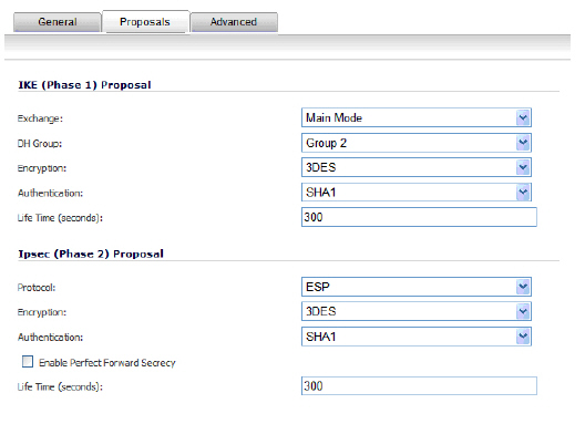
In the IKE (Phase 1) Proposal section, use the following settings:
Select the DH Group from the DH Group menu.
NoteThe Windows 2000 L2TP client and Windows XP L2TP client can only work with DH Group 2. They are incompatible with DH Groups 1 and 5.
Select 3DES, AES-128, or AES-256 from the Encryption menu.
Select the desired authentication method from the Authentication menu.
Enter a value in the Life Time (seconds) field. The default setting of 28800 forces the tunnel to renegotiate and exchange keys every 8 hours.
In the IPsec (Phase 2) Proposal section, select the following settings:
Select the desired protocol from the Protocol menu.
Select 3DES, AES-128, or AES-256 from the Encryption menu.
Select the desired authentication method from the Authentication menu.
Select Enable Perfect Forward Secrecy if you want an additional Diffie-Hellman key exchange as an added layer of security. Select Group 2 from the DH Group menu.
NoteThe Windows 2000 L2TP client and Windows XP L2TP client can only work with DH Group 2. They are incompatible with DH Groups 1 and 5.
Enter a value in the Life Time (seconds) field. The default setting of 28800 forces the tunnel to renegotiate and exchange keys every 8 hours.
Click the Advanced tab.
Select any of the following optional settings you want to apply to your GroupVPN policy:
Enable Windows Networking (NetBIOS) broadcast - Allows access to remote network resources by browsing the Windows® Network Neighborhood.
Enable Multicast - Enables IP multicasting traffic, such as streaming audio (including VoIP) and video applications, to pass through the VPN tunnel.
Management via this SA: - If using the VPN policy to manage the SonicWALL security appliance, select the management method, either HTTP or HTTPS.
Default Gateway - Allows the network administrator to specify the IP address of the default network route for incoming IPsec packets for this VPN policy. Incoming packets are decoded by the SonicWALL and compared to static routes configured in the SonicWALL security appliance. Since packets can have any IP address destination, it is impossible to configure enough static routes to handle the traffic. For packets received via an IPsec tunnel, the SonicWALL looks up a route. If no route is found, the security appliance checks for a Default Gateway. If a Default Gateway is detected, the packet is routed through the gateway. Otherwise, the packet is dropped.
Require Authentication of VPN Clients via XAUTH - Requires that all inbound traffic on this VPN tunnel is from an authenticated user. Unauthenticated traffic is not allowed on the VPN tunnel. he Trusted users group is selected by default. You can select another user group or Everyone from User Group for XAUTH users.
Allow Unauthenticated VPN Client Access - Allows you to enable unauthenticated VPN client access. If you uncheck Require Authentication of VPN Clients via XAUTH, the Allow Unauthenticated VPN Client Access menu is activated. Select an Address Object or Address Group from menu of predefined options, or select Create new address object or Create new address group to create a new one.
Click the Client tab, select any of the following settings you want to apply to your GroupVPN policy.
Cache XAUTH User Name and Passwordon Client - Allows the Global VPN Client to cache the user name and password.
Never - Global VPN Client is not allowed to cache the username and password. The user will be prompted for a username and password when the connection is enabled, and also every time there is an IKE Phase 1 rekey.
Single Session - Global VPN Client user prompted for username and password each time the connection is enabled and will be valid until the connection is disabled. The username and password is used through IKE Phase 1 rekey.
Always - Global VPN Client user prompted for username and password only once when connection is enabled. When prompted, the user will be given the option of caching the username and password.
Virtual Adapter Settings - The use of the Virtual Adapter by the Global VPN Client (GVC) is dependent upon a DHCP server, either the internal SonicOS or a specified external DHCP server, to allocate addresses to the Virtual Adapter. In instances where predictable addressing was a requirement, it is necessary to obtain the MAC address of the Virtual Adapter, and to create a DHCP lease reservation. To reduce the administrative burden of providing predictable Virtual Adapter addressing, you can configure the GroupVPN to accept static addressing of the Virtual Adapter's IP configuration. This feature requires the use of GVC version 3.0 or later.
None - A Virtual Adapter will not be used by this GroupVPN connection.
DHCP Lease - The Virtual Adapter will obtain its IP configuration from the DHCP Server only, as configure in the VPN > DHCP over VPN page.
DHCP Lease or Manual Configuration - When the GVC connects to the SonicWALL, the policy from the SonicWALL instructs the GVC to use a Virtual Adapter, but the DHCP messages are suppressed if the Virtual Adapter has been manually configured. The configured value is recorded by the SonicWALL so that it can proxy ARP for the manually assigned IP address. By design, there are currently no limitations on IP address assignments for the Virtual Adapter. Only duplicate static addresses are not permitted.
Allow Connections to - Client network traffic matching destination networks of each gateway is sent through the VPN tunnel of that specific gateway.
This Gateway Only - Allows a single connection to be enabled at a time. Traffic that matches the destination networks as specified in the policy of the gateway is sent through the VPN tunnel. If this option is selected along with Set Default Route as this Gateway, then the Internet traffic is also sent through the VPN tunnel. If this option is selected without selecting Set Default Route as this Gateway, then the Internet traffic is blocked.
All Secured Gateways - Allows one or more connections to be enabled at the same time. Traffic matching the destination networks of each gateway is sent through the VPN tunnel of that specific gateway. If this option is selected along with Set Default Route as this Gateway, then Internet traffic is also sent through the VPN tunnel. If this option is selected without Set Default Route as this Gateway, then the Internet traffic is blocked. Only one of the multiple gateways can have Set Default Route as this Gateway enabled.
Split Tunnels - Allows the VPN user to have both local Internet connectivity and VPN connectivity.
Set Default Route as this Gateway - Enable this check box if all remote VPN connections access the Internet through this VPN tunnel. You can only configure one VPN policy to use this setting.
Use Default Key for Simple Client Provisioning - uses Aggressive mode for the initial exchange with the gateway and VPN clients uses a default Preshared Key for authentication.
Click OK.
Configuring GroupVPN with IKE using 3rd Party Certificates
To configure GroupVPN with IKE using 3rd Party Certificates, follow these steps:
CautionBefore configuring GroupVPN with IKE using 3rd Party Certificates, your certificates must be installed on the SonicWALL.
In the VPN > Settings page click the edit icon under Configure. The VPN Policy window is displayed.
In the Security Policy section, select IKE using 3rd Party Certificates from the Authentication Method menu. The VPN policy name is GroupVPN by default and cannot be changed.
Select a certificate for the SonicWALL from the Gateway Certificate menu.
Select one of the following Peer ID types from the Peer ID Type menu:
E-Mail ID and Domain Name - The Email ID and Domain Name types are based on the certificate's Subject Alternative Name field, which is not contained in all certificates by default. If the certificate does not contain a Subject Alternative Name field, this filter will not work. The E-Mail ID and Domain Name filters can contain a string or partial string identifying the acceptable range required. The strings entered are not case sensitive and can contain the wild card characters * (for more than 1 character) and ? (for a single character). For example, the string *@sonicwall.com when E-Mail ID is selected, would allow anyone with an email address that ended in sonicwall.com to have access; the string *sv.us.sonicwall.com when Domain Name is selected, would allow anyone with a domain name that ended in sv.us.sonicwall.com to have access.
Distinguished Name - based on the certificates Subject Distinguished Name field, which is contained in all certificates by default. The format of any Subject Distinguished Name is determined by the issuing Certificate Authority. Common fields are Country (C=), Organization (O=), Organizational Unit (OU=), Common Name (CN=), Locality (L=), and vary with the issuing Certificate Authority. The actual Subject Distinguished Name field in an X.509 Certificate is a binary object which must be converted to a string for matching purposes. The fields are separated by the forward slash character, for example: /C=US/O=SonicWALL, Inc./OU=TechPubs/CN=Joe Pub
Up to three organizational units can be specified. The usage is c=*;o=*;ou=*;ou=*;ou=*;cn=*. The final entry does not need to contain a semi-colon. You must enter at least one entry, i.e. c=us.
Enter the Peer ID filter in the Peer ID Filter field.
Check Allow Only Peer Certificates Signed by Gateway Issuer to specify that peer certificates must be signed by the issuer specified in the Gateway Certificate menu.
Click on the Proposals tab.
In the IKE (Phase 1) Proposal section, select the following settings:
Select the DH Group from the DH Group menu.
NoteThe Windows 2000 L2TP client and Windows XP L2TP client can only work with DH Group 2. They are incompatible with DH Groups 1 and 5.
Select 3DES, AES-128, or AES-256 from the Encryption menu.
Select the desired authentication method from the Authentication menu.
Enter a value in the Life Time (seconds) field. The default setting of 28800 forces the tunnel to renegotiate and exchange keys every 8 hours.
In the IPsec (Phase 2) Proposal section, select the following settings:
Select the desired protocol from the Protocol menu.
Select 3DES, AES-128, or AES-256 from the Encryption menu.
Select the desired authentication method from the Authentication menu.
Select Enable Perfect Forward Secrecy if you want an additional Diffie-Hellman key exchange as an added layer of security. Select Group 2 from the DH Group menu.
NoteThe Windows 2000 L2TP client and Windows XP L2TP client can only work with DH Group 2. They are incompatible with DH Groups 1 and 5.
Enter a value in the Life Time (seconds) field. The default setting of 28800 forces the tunnel to renegotiate and exchange keys every 8 hours.
Click on the Advanced tab and select any of the following optional settings that you want to apply to your GroupVPN Policy:
Enable Windows Networking (NetBIOS) broadcast - Allows access to remote network resources by browsing the Windows Network Neighborhood.
Enable Multicast - Enables IP multicasting traffic, such as streaming audio (including VoIP) and video applications, to pass through the VPN tunnel.
Management via this SA - If using the VPN policy to manage the SonicWALL security appliance, select the management method, either HTTP or HTTPS.
Default Gateway - Used at a central site in conjunction with a remote site using the Route all Internet traffic through this SA check box. Default LAN Gateway allows the network administrator to specify the IP address of the default LAN route for incoming IPsec packets for this SA. Incoming packets are decoded by the SonicWALL and compared to static routes configured in the SonicWALL. Since packets can have any IP address destination, it is impossible to configure enough static routes to handle the traffic. For packets received via an IPsec tunnel, the SonicWALL looks up a route for the LAN. If no route is found, the SonicWALL checks for a Default LAN Gateway. If a Default LAN Gateway is detected, the packet is routed through the gateway. Otherwise, the packet is dropped.
Require Authentication of VPN Clients via XAUTH - Requires that all inbound traffic on this VPN policy is from an authenticated user. Unauthenticated traffic is not allowed on the VPN tunnel.
User group for XAUTH users - Allows you to select a defined user group for authentication.
All Unauthenticated VPN Client Access - Allows you to specify network segments for unauthenticated Global VPN Client access.
Click on the Client tab and select any of the following boxes that you want to apply to Global VPN Client provisioning:
Cache XAUTH User Name and Password - Allows the Global VPN Client to cache the user name and password. Select from:
Never - Global VPN Client is not allowed to cache username and password. The user will be prompted for a username and password when the connection is enabled and also every time there is an IKE phase 1 rekey.
Single Session - The user will be prompted for username and password each time the connection is enabled and will be valid until the connection is disabled. This username and password is used through IKE phase 1 rekey.
Always - The user will be prompted for username and password only once when connection is enabled. When prompted, the user will be given the option of caching the username and password.
Virtual Adapter Settings - The use of the Virtual Adapter by the Global VPN Client (GVC) is dependent upon a DHCP server, either the internal SonicOS or a specified external DHCP server, to allocate addresses to the Virtual Adapter. In instances where predictable addressing was a requirement, it is necessary to obtain the MAC address of the Virtual Adapter, and to create a DHCP lease reservation. To reduce the administrative burden of providing predictable Virtual Adapter addressing, you can configure the GroupVPN to accept static addressing of the Virtual Adapter's IP configuration. This feature requires the use of GVC version 3.0 or later.
None - A Virtual Adapter will not be used by this GroupVPN connection.
DHCP Lease - The Virtual Adapter will obtain its IP configuration from the DHCP Server only, as configure in the VPN > DHCP over VPN page.
DHCP Lease or Manual Configuration - When the GVC connects to the SonicWALL, the policy from the SonicWALL instructs the GVC to use a Virtual Adapter, but the DHCP messages are suppressed if the Virtual Adapter has been manually configured. The configured value is recorded by the SonicWALL so that it can proxy ARP for the manually assigned IP address. By design, there are currently no limitations on IP address assignments for the Virtual Adapter. Only duplicate static addresses are not permitted.
Allow Connections to - Client network traffic matching destination networks of each gateway is sent through the VPN tunnel of that specific gateway.
This Gateway Only - Allows a single connection to be enabled at a time. Traffic that matches the destination networks as specified in the policy of the gateway is sent through the VPN tunnel. If this option is selected along with Set Default Route as this Gateway, then the Internet traffic is also sent through the VPN tunnel. If this option is selected without selecting Set Default Route as this Gateway, then the Internet traffic is blocked.
All Secured Gateways - Allows one or more connections to be enabled at the same time. Traffic matching the destination networks of each gateway is sent through the VPN tunnel of that specific gateway. If this option is selected along with Set Default Route as this Gateway, then Internet traffic is also sent through the VPN tunnel. If this option is selected without Set Default Route as this Gateway, then the Internet traffic is blocked. Only one of the multiple gateways can have Set Default Route as this Gateway enabled.
Split Tunnels - Allows the VPN user to have both local Internet connectivity and VPN connectivity.
Set Default Route as this Gateway - Enable this check box if all remote VPN connections access the Internet through this SA. You can only configure one SA to use this setting.
Use Default Key for Simple Client Provisioning - Uses Aggressive mode for the initial exchange with the gateway and VPN clients uses a default Preshared Key for authentication.
Click OK.
Exporting a VPN Client Policy
If you want to export the Global VPN Client configuration settings to a file for users to import into their Global VPN Clients, follow these instructions:
CautionThe GroupVPN SA must be enabled on the SonicWALL to export a configuration file.
Click the Disk icon in the Configure column for the GroupVPN entry in the VPN Policies table. The Export VPN Client Policy window appears.
rcf format is required for SonicWALL Global VPN Clients is selected by default. Files saved in the rcf format can be password encrypted. The SonicWALL provides a default file name for the configuration file, which you can change.
Click Yes. The VPN Policy Export window appears.
Type a password in the Password field and reenter it in the Confirm Password field, if you want to encrypt the exported file. If you choose not to enter a password, the exported file is not encrypted.
Click Submit. If you did not enter a password, a message appears confirming your choice.
Click OK. You can change the configuration file before saving.
Save the file.
Click Close.
The file can be saved to a floppy disk or sent electronically to remote users to configure their Global VPN Clients.
Site-to-Site VPN Configurations
When designing VPN connections, be sure to document all pertinent IP addressing information and create a network diagram to use as a reference. A sample planning sheet is provided on the next page. The SonicWALL must have a routable WAN IP address whether it is dynamic or static. In a VPN network with dynamic and static IP addresses, the VPN gateway with the dynamic address must initiate the VPN connection.
Site-to-Site VPN configurations can include the following options:
Branch Office (Gateway to Gateway) - A SonicWALL is configured to connect to another SonicWALL via a VPN tunnel. Or, a SonicWALL is configured to connect via IPsec to another manufacturer’s firewall.
Hub and Spoke Design - All SonicWALL VPN gateways are configured to connect to a central SonicWALL (hub), such as a corporate SonicWALL. The hub must have a static IP address, but the spokes can have dynamic IP addresses. If the spokes are dynamic, the hub must be a SonicWALL.
Mesh Design - All sites connect to all other sites. All sites must have static IP addresses.
Creating Site-to-Site VPN Policies
TipYou can easily create site-to-site VPN policies using the VPN Policy Wizard. For complete step-by-step instructions on using the VPN Policy Wizard, see Wizards > VPN Wizard.
You can create or modify existing VPN policies using the VPN Policy window. Clicking the Add button under the VPN Policies table displays the VPN Policy window for configuring the following IPsec Keying mode VPN policies:
This section also contains information on configuring a static route to act as a failover in case the VPN tunnel goes down. See Configuring VPN Failover to a Static Routefor more information.
TipUse the VPN Planning Sheet for Site-to-Site VPN Policies to record your settings. These settings are necessary to configure the remote SonicWALL and create a successful VPN connection.
NoteFor configuring VPN policies between SonicWALL security appliances running SonicOS Enhanced and SonicWALL security appliances running SonicWALL Firmware version 6.5 (or higher), see the technote: Creating IKE IPsec VPN Tunnels between SonicWALL Firmware 6.5 and SonicOS Enhanced, available at the SonicWALL documentation Web site http://www.sonicwall.com/us/Support.html.
Configuring a VPN Policy with IKE using Preshared Secret
To configure a VPN Policy using Internet Key Exchange (IKE), follow the steps below:
Click Add on the VPN > Settings page. The VPN Policy window is displayed.
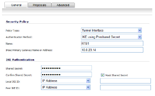
In the General tab, select IKE using Preshared Secret from the Authentication Method menu.
Enter a name for the policy in the Name field.
Enter the host name or IP address of the remote connection in the IPsec Primary Gateway Name or Address field.
If the Remote VPN device supports more than one endpoint, you may optionally enter a second host name or IP address of the remote connection in the IPsec Secondary Gateway Name or Address field.
NoteSecondary gateways are not supported with IKEv2.
Enter a Shared Secret password to be used to setup the Security Association the Shared Secret and Confirm Shared Secret fields. The Shared Secret must be at least 4 characters long, and should comprise both numbers and letters.
Optionally, specify a Local IKE ID (optional) and Peer IKE ID (optional) for this Policy. By default, the IP Address (ID_IPv4_ADDR) is used for Main Mode negotiations, and the SonicWALL Identifier (ID_USER_FQDN) is used for Aggressive Mode.
Click the Network tab.
Under Local Networks, select a local network from Choose local network from list if a specific local network can access the VPN tunnel. If hosts on this side of the VPN connection will be obtaining their addressing from a DHCP server on the remote side of the tunnel, select Local network obtains IP addresses using DHCP through this VPN tunnel. If traffic can originate from any local network, select Any Address. Use this option if a peer has Use this VPN tunnel as default route for all Internet traffic selected.
NoteDHCP over VPN is not supported with IKEv2.
Under Destination Networks, select Use this VPN Tunnel as default route for all Internet traffic if traffic from any local user cannot leave the SonicWALL security appliance unless it is encrypted. You can only configure one SA to use this setting. If the remote side of this VPN connection is be obtaining its addressing from a DHCP server on this side of the tunnel, select Destination network obtains IP addresses using DHCP server through this tunnel. Alternatively, select Choose Destination network from list, and select the address object or group.
If IKEv2 is selected for the Exchange method on the Proposals tab, a third option is available under Destination Networks: the use IKEv2 IP pool option assigns remote clients with an IP address from the selected IP address pool.
Click the Proposals tab.
Under IKE (Phase 1) Proposal, select either Main Mode, Aggressive Mode, or IKEv2 from the Exchange menu. Aggressive Mode is generally used when WAN addressing is dynamically assigned. IKEv2 causes all the negotiation to happen via IKEv2 protocols, rather than using IKE Phase 1 and Phase 2. If you use IKEv2, both ends of the VPN tunnel must use IKEv2.
Under IKE (Phase 1) Proposal, the default values for DH Group, Encryption, Authentication, and Life Time are acceptable for most VPN configurations. Be sure the Phase 1 values on the opposite side of the tunnel are configured to match. You can also choose AES-128, AES-192, or AES-256 from the Authentication menu instead of 3DES for enhanced authentication security.
NoteThe Windows 2000 L2TP client and Windows XP L2TP client can only work with DH Group 2. They are incompatible with DH Groups 1 and 5.
Under IPsec (Phase 2) Proposal, the default values for Protocol, Encryption, Authentication, Enable Perfect Forward Secrecy, DH Group, and Lifetime are acceptable for most VPN SA configurations. Be sure the Phase 2 values on the opposite side of the tunnel are configured to match.
Click the Advanced tab and select any of the following optional settings you want to apply to your VPN policy:
If you selected Main Mode or Aggressive Mode in the Proposals tab, the following options are displayed:
Select Enable Keep Alive to use heartbeat messages between peers on this VPN tunnel. If one end of the tunnel fails, using Keepalives will allow for the automatic renegotiation of the tunnel once both sides become available again without having to wait for the proposed Life Time to expire.
The Suppress automatic Access Rules creation for VPN Policy setting is not enabled by default to allow the VPN traffic to traverse the appropriate zones.
To require XAUTH authentication by users prior to allowing traffic to traverse this tunnel, select Require authentication of VPN client by XAUTH, and select a User group to specify allowed users from the User group for XAUTH.
Select Enable Windows Networking (NetBIOS) Broadcast to allow access to remote network resources by browsing the Windows® Network Neighborhood.
Select Enable Multicast to allow IP multicasting traffic, such as streaming audio (including VoIP) and video applications, to pass through the VPN tunnel.
Select Apply NAT Policies if you want the SonicWALL to translate the Local, Remote or both networks communicating via this VPN tunnel. To perform Network Address Translation on the Local Network, select or create an Address Object in the Translated Local Network menu. To translate the Remote Network, select or create an Address Object in the Translated Remote Network menu. Generally, if NAT is required on a tunnel, either Local or Remote should be translated, but not both. Apply NAT Policies is particularly useful in cases where both sides of a tunnel use either the same or overlapping subnets.
To manage the local SonicWALL through the VPN tunnel, select HTTP, HTTPS, or both from Management via this SA. Select HTTP, HTTPS, or both in the User login via this SA to allow users to login using the SA.
If you wish to use a router on the LAN for traffic entering this tunnel destined for an unknown subnet, for example, if you configured the other side to Use this VPN Tunnel as default route for all Internet traffic, you should enter the IP address of your router into the Default LAN Gateway (optional) field.
Select an interface or zone from the VPN Policy bound to menu. A Zone WAN is the preferred selection if you are using WAN Load Balancing and you wish to allow the VPN to use either WAN interface.
If you selected IKEv2 in the Proposals tab, the following options are displayed:
Select Enable Keep Alive to use heartbeat messages between peers on this VPN tunnel. If one end of the tunnel fails, using Keepalives will allow for the automatic renegotiation of the tunnel once both sides become available again without having to wait for the proposed Life Time to expire.
Select Suppress automatic Access Rules creation for VPN Policy to turn off the automatic access rules created between the LAN and VPN zones for this VPN policy.
Select Enable Windows Networking (NetBIOS) Broadcast to allow access to remote network resources by browsing the Windows® Network Neighborhood.
Select Enable Multicast to allow IP multicasting traffic, such as streaming audio (including VoIP) and video applications, to pass through the VPN tunnel.
Select Apply NAT Policies if you want the SonicWALL to translate the Local, Remote or both networks communicating via this VPN tunnel. To perform Network Address Translation on the Local Network, select or create an Address Object in the Translated Local Network menu. To translate the Remote Network, select or create an Address Object in the Translated Remote Network menu. Generally, if NAT is required on a tunnel, either Local or Remote should be translated, but not both. Apply NAT Policies is particularly useful in cases where both sides of a tunnel use either the same or overlapping subnets.
To manage the local SonicWALL through the VPN tunnel, select HTTP, HTTPS, or both from Management via this SA. Select HTTP, HTTPS, or both in the User login via this SA to allow users to login using the SA.
Enter the Default LAN Gateway if you have more than one gateway and you want this one always to be used first.
Select an interface or zone from the VPN Policy bound to menu. A Zone WAN is the preferred selection if you are using WAN Load Balancing and you wish to allow the VPN to use either WAN interface.
Under IKEv2 Settings (visible only if you selected IKEv2 for Exchange on the Proposals tab), The Do not send trigger packet during IKE SA negotiation checkbox is cleared by default and should only be selected when required for interoperability.
The term Trigger Packet refers to the use of initial Traffic Selector payloads populated with the IP addresses from the packet that caused SA negotiation to begin. It is recommended practice to include Trigger Packets to assist the IKEv2 Responder in selecting the correct protected IP address ranges from its Security Policy Database. Not all implementations support this feature, so it may be appropriate to disable the inclusion of Trigger Packets to some IKE peers.
Select Accept Hash & URL Certificate Type to have the appliance accept a hash and URL of the certificate instead of the actual certificate itself. This is generally used for peers that have limited memory or bandwidth (such as mobile devices). The advantage is that the hash and URL are substantially smaller than the actual certificate. The disadvantage is that the appliance is must use the URL to retrieve the certificate and then use the hash to validate the certificate. This uses some processing power of the appliance. It also results in a longer time needed to complete the IKEv2 phase 1 negotiation.
Select Send Hash & URL Certificate Type to have the appliance send a hash and URL of the certificate instead of the actual certificate itself. See above for the advantaged and disadvantages of this process.
Click OK.
Configuring a VPN Policy using Manual Key
To manually configure a VPN policy between two SonicWALL appliances using Manual Key, follow the steps below:
Configuring the Local SonicWALL Security Appliance
Click Add on the VPN > Settings page. The VPN Policy window is displayed.
In the General tab of the VPN Policy window, select Manual Key from the IPsec Keying Mode menu. The VPN Policy window displays the manual key options.
Enter a name for the policy in the Name field.
Enter the host name or IP address of the remote connection in the IPsec Gateway Name or Address field.
Click the Network tab.
Select a local network from Choose local network from list if a specific local network can access the VPN tunnel. If traffic can originate from any local network, select AnyAddress. Use this option is a peer has Use this VPN Tunnel as default route for all Internet traffic selected. You can only configure one SA to use this setting. Alternatively, select Choose Destination network from list, and select the address object or group.
Click on the Proposals tab.
Define an Incoming SPI and an Outgoing SPI. The SPIs are hexadecimal (0123456789abcedf) and can range from 3 to 8 characters in length.
CautionEach Security Association must have unique SPIs; no two Security Associations can share the same SPIs. However, each Security Association Incoming SPI can be the same as the Outgoing SPI.
The default values for Protocol, Phase 2 Encryption, and Phase 2 Authentication are acceptable for most VPN SA configurations.
NoteThe values for Protocol, Phase 2 Encryption, and Phase 2 Authentication must match the values on the remote SonicWALL.
Enter a 16 character hexadecimal encryption key in the Encryption Key field or use the default value. This encryption key is used to configure the remote SonicWALL encryption key, therefore, write it down to use when configuring the SonicWALL.
Enter a 32 character hexadecimal authentication key in the Authentication Key field or use the default value. Write down the key to use while configuring the SonicWALL settings.
TipValid hexadecimal characters include 0, 1, 2, 3, 4, 5, 6, 7, 8, 9, a, b, c, d, e, and f. 1234567890abcdef is an example of a valid DES or ARCFour encryption key. If you enter an incorrect encryption key, an error message is displayed at the bottom of the browser window.
Click the Advanced tab and select any of the following optional settings you want to apply to your VPN policy.
The Suppress automatic Access Rules creation for VPN Policy setting is not enabled by default to allow the VPN traffic to traverse the appropriate zones.
Select Enable Windows Networking (NetBIOS) broadcast to allow access to remote network resources by browsing the Windows® Network Neighborhood.
Select Apply NAT Policies if your want the SonicWALL to translate the Local, Remote or both networks communicating via this VPN tunnel. To perform Network Address Translation on the Local Network, select or create an Address Object in the Translated Local Network drop-down box. To translate the Remote Network, select or create an Address Object in the Translated Remote Network drop-down box. Generally, if NAT is required on a tunnel, either Local or Remote should be translated, but not both. Apply NAT Policies is particularly useful in cases where both sides of a tunnel use either the same or overlapping subnets.
To manage the local SonicWALL through the VPN tunnel, select HTTP, HTTPS, or both from Management via this SA.
Select HTTP, HTTPS, or both in the User login via this SA to allow users to login using the SA.
If you have an IP address for a gateway, enter it into the Default LAN Gateway (optional) field.
Select an interface from the VPN Policy bound to menu.
Click OK.
Click Accept on the VPN > Settings page to update the VPN Policies.
Configuring the Remote SonicWALL Security Appliance
Click Add on the VPN > Settings page. The VPN Policy window is displayed.
In the General tab, select Manual Key from the IPsec Keying Mode menu.
Enter a name for the SA in the Name field.
Enter the host name or IP address of the local connection in the IPsec Gateway Name or Address field.
Click the Network tab.
Select a local network from Choose local network from list if a specific local network can access the VPN tunnel. If traffic can originate from any local network, select AnyAddress. Select Use this VPN Tunnel as default route for all Internet traffic if traffic from any local user cannot leave the SonicWALL security appliance unless it is encrypted. You can only configure one SA to use this setting. Alternatively, select Choose Destination network from list, and select the address object or group.
Click the Proposals tab.
Define an Incoming SPI and an Outgoing SPI. The SPIs are hexadecimal (0123456789abcedf) and can range from 3 to 8 characters in length.
WarningEach Security Association must have unique SPIs; no two Security Associations can share the same SPIs. However, each Security Association Incoming SPI can be the same as the Outgoing SPI.
The default values for Protocol, Phase 2 Encryption, and Phase 2 Authentication are acceptable for most VPN SA configurations.
NoteThe values for Protocol, Phase 2 Encryption, and Phase 2 Authentication must match the values on the remote SonicWALL.
Enter a 16 character hexadecimal encryption key in the Encryption Key field or use the default value. This encryption key is used to configure the remote SonicWALL encryption key, therefore, write it down to use when configuring the remote SonicWALL.
Enter a 32 character hexadecimal authentication key in the Authentication Key field or use the default value. Write down the key to use while configuring the remote SonicWALL settings.
TipValid hexadecimal characters include 0, 1, 2, 3, 4, 5, 6, 7, 8, 9, a, b, c, d, e, and f. 1234567890abcdef is an example of a valid DES or ARCFour encryption key. If you enter an incorrect encryption key, an error message is displayed at the bottom of the browser window.
Click the Advanced tab and select any of the following optional settings you want to apply to your VPN policy:
The Suppress automatic Access Rules creation for VPN Policy setting is not enabled by default to allow the VPN traffic to traverse the appropriate zones.
Select Enable Windows Networking (NetBIOS) broadcast to allow access to remote network resources by browsing the Windows® Network Neighborhood.
Select Apply NAT Policies if you want the SonicWALL to translate the Local, Remote or both networks communicating via this VPN tunnel. To perform Network Address Translation on the Local Network, select or create an Address Object in the Translated Local Network drop-down box. To translate the Remote Network, select or create an Address Object in the Translated Remote Network drop-down box. Generally, if NAT is required on a tunnel, either Local or Remote should be translated, but not both. Apply NAT Policies is particularly useful in cases where both sides of a tunnel use either the same or overlapping subnets.
WarningYou cannot use this feature if you have selected Use this VPN Tunnel as the default route for all Internet traffic on the Network tab.
To manage the remote SonicWALL through the VPN tunnel, select HTTP, HTTPS, or both from Management via this SA.
Select HTTP, HTTPS, or both in the User login via this SA to allow users to login using the SA.
If you have an IP address for a gateway, enter it into the Default LAN Gateway (optional) field.
Select an interface from the VPN Policy bound to menu.
Click OK.
Click Accept on the VPN > Settings page to update the VPN Policies.
TipSince Window Networking (NetBIOS) has been enabled, users can view remote computers in their Windows Network Neighborhood. Users can also access resources on the remote LAN by entering servers’ or workstations’ remote IP addresses.
Configuring a VPN Policy with IKE using a Third Party Certificate
WarningYou must have a valid certificate from a third party Certificate Authority installed on your SonicWALL before you can configure your VPN policy with IKE using a third party certificate.
To create a VPN SA using IKE and third party certificates, follow these steps:
In the VPN > Settings page, click Add. The VPN Policy window is displayed.
In the Authentication Method list in the General tab, select IKE using 3rd Party Certificates.The VPN Policy window displays the 3rd party certificate options.
Type a Name for the Security Association in the Name field.
Type the IP address or Fully Qualified Domain Name (FQDN) of the primary remote SonicWALL in the IPsec Primary Gateway Name or Address field. If you have a secondary remote SonicWALL, enter the IP address or Fully Qualified Domain Name (FQDN) in the IPsec Secondary Gateway Name or Address field.
Under IKE Authentication, select a third party certificate from the Local Certificate list. You must have imported local certificates before selecting this option.
Select one of the following Peer ID types from the Peer IKE ID Type menu:
E-Mail ID and Domain Name - The Email ID and Domain Name types are based on the certificate's Subject Alternative Name field, which is not contained in all certificates by default. If the certificate contains a Subject Alternative Name, that value must be used. For site-to-site VPNs, wild card characters (such as * for more than 1 character or ? for a single character) cannot be used. The full value of the E-Mail ID or Domain Name must be entered. This is because site-to-site VPNs are expected to connect to a single peer, as opposed to Group VPNs, which expect multiple peers to connect.
Distinguished Name - Based on the certificates Subject Distinguished Name field, which is contained in all certificates by default. As with the E-Mail ID and Domain Name above, the entire Distinguished Name field must be entered for site-to-site VPNs Wild card characters are not supported.
The format of any Subject Distinguished Name is determined by the issuing Certificate Authority. Common fields are Country (C=), Organization (O=), Organizational Unit (OU=), Common Name (CN=), Locality (L=), and vary with the issuing Certificate Authority. The actual Subject Distinguished Name field in an X.509 Certificate is a binary object which must be converted to a string for matching purposes. The fields are separated by the forward slash character, for example: /C=US/O=SonicWALL, Inc./OU=TechPubs/CN=Joe Pub
To find the certificate details (Subject Alternative Name, Distinguished Name, etc.), navigate to the System > Certificates page and click on the Export button for the certificate.
Type an ID string in the Peer IKE ID field.
Click on the Network tab.
Under Local Networks, select a local network from Choose local network from list if a specific local network can access the VPN tunnel. If hosts on this side of the VPN connection will be obtaining their addressing from a DHCP server on the remote side of the tunnel, select Local network obtains IP addresses using DHCP through this VPN tunnel. If traffic can originate from any local network, select Any Address.
Under Destination Networks, select Use this VPN Tunnel as default route for all Internet traffic if traffic from any local user cannot leave the SonicWALL security appliance unless it is encrypted. You can only configure one SA to use this setting. If the remote side of this VPN connection is be obtaining its addressing from a DHCP server on this side of the tunnel, select Destination network obtains IP addresses using DHCP server through this tunnel. Alternatively, select Choose Destination network from list, and select the address object or group.
Click the Proposals tab.
In the IKE (Phase 1) Proposal section, select the following settings:
Select Main Mode or Aggressive Mode from the Exchange menu.
Select the desired DH Group from the DH Group menu.
NoteThe Windows 2000 L2TP client and Windows XP L2TP client can only work with DH Group 2. They are incompatible with DH Groups 1 and 5.
Select 3DES, AES-128, AES-192, or AES-256 from the Encryption menu.
Select the desired authentication method from the Authentication menu.
Enter a value in the Life Time (seconds) field. The default setting of 28800 forces the tunnel to renegotiate and exchange keys every 8 hours.
In the IPsec (Phase 2) Proposal section, select the following settings:
Select the desired protocol from the Protocol menu.
Select 3DES, AES-128, AES-192, or AES-256 from the Encryption menu.
Select the desired authentication method from the Authentication menu.
Select Enable Perfect Forward Secrecy if you want an additional Diffie-Hellman key exchange as an added layer of security. Select Group 2 from the DH Group menu.
NoteThe Windows 2000 L2TP client and Windows XP L2TP client can only work with DH Group 2. They are incompatible with DH Groups 1 and 5.
Enter a value in the Life Time (seconds) field. The default setting of 28800 forces the tunnel to renegotiate and exchange keys every 8 hours.
Click the Advanced tab. Select any optional configuration options you want to apply to your VPN policy:
Select Enable Keep Alive to use heartbeat messages between peers on this VPN tunnel. If one end of the tunnel fails, using Keepalives will allow for the automatic renegotiation of the tunnel once both sides become available again without having to wait for the proposed Life Time to expire.
The Suppress automatic Access Rules creation for VPN Policy setting is not enabled by default to allow the VPN traffic to traverse the appropriate zones.
To require XAUTH authentication by users prior to allowing traffic to traverse this tunnel, select Require authentication of VPN client by XAUTH, and select a User group to specify allowed users from the User group for XAUTH.
Select Enable Windows Networking (NetBIOS) Broadcast to allow access to remote network resources by browsing the Windows® Network Neighborhood.
Select Enable Multicast to allow multicast traffic through the VPN tunnel.
Select Apply NAT Policies if you want the SonicWALL to translate the Local, Remote or both networks communicating via this VPN tunnel. To perform Network Address Translation on the Local Network, select or create an Address Object in the Translated Local Network menu. To translate the Remote Network, select or create an Address Object in the Translated Remote Network menu. Generally, if NAT is required on a tunnel, either Local or Remote should be translated, but not both. Apply NAT Policies is particularly useful in cases where both sides of a tunnel use either the same or overlapping subnets.
To manage the remote SonicWALL through the VPN tunnel, select HTTP, HTTPS, or both from Management via this SA. Select HTTP, HTTPS, or both in the User login via this SA to allow users to login using the SA.
If you wish to use a router on the LAN for traffic entering this tunnel destined for an unknown subnet, for example, if you configured the other side to Use this VPN Tunnel as default route for all Internet traffic, you should enter the IP address of your router into the Default LAN Gateway (optional) field.
Select an interface or zone from the VPN Policy bound to menu. A zone is the preferred selection if you are using WAN Load Balancing and you wish to allow the VPN to use either WAN interface.
Click OK.
Configuring VPN Failover to a Static Route
Optionally, you can configure a static route to be used as a backup route in case the VPN tunnel goes down. The Allow VPN path to take precedence option allows you to create a backup route for a VPN tunnel. By default, static routes have a metric of one and take precedence over VPN traffic. The Allow VPN path to take precedence option gives precedence over the route to VPN traffic to the same destination address object. This results in the following behavior:
When a VPN tunnel is active: static routes matching the destination address object of the VPN tunnel are automatically disabled if the Allow VPN path to take precedence option is enabled. All traffic is routed over the VPN tunnel to the destination address object.
When a VPN tunnel goes down: static routes matching the destination address object of the VPN tunnel are automatically enabled. All traffic to the destination address object is routed over the static routes.
To configure a static route as a VPN failover, complete the following steps:
Navigate to the Network > Routing page.
Scroll to the bottom of the page and click on the Add button. The Add Route Policy window is displayed.
Select the appropriate Source, Destination, Service, Gateway, and Interface.
Leave the Metric as 1.
Enable the Allow VPN path to take precedence checkbox.
Click OK.
For more information on configuring static routes and Policy Based Routing, see Network > Routing.
Route Based VPN
A policy-based approach forces the VPN policy configuration to include the network topology configuration. This makes it difficult for the network administrator to configure and maintain the VPN policy with a constantly changing network topology.
With the Route Based VPN approach, network topology configuration is removed from the VPN policy configuration. The VPN policy configuration creates a Tunnel Interface between two end points. Static or Dynamic routes can then be added to the Tunnel Interface. The Route Based VPN approach moves network configuration from the VPN policy configuration to Static or Dynamic Route configuration.
Not only does Route Based VPN make configuring and maintaining the VPN policy easier, a major advantage of the Route Based VPN feature is that it provides flexibility on how traffic is routed. With this feature, users can now define multiple paths for overlapping networks over a clear or redundant VPN.
Using Route Based VPN
Route Based VPN configuration is a two step process. The first step involves creating a Tunnel Interface. The crypto suites used to secure the traffic between two end-points are defined in the Tunnel Interface. The second step involves creating a static or dynamic route using Tunnel Interface.
The Tunnel Interface is created when a Policy of type “Tunnel Interface” is added for the remote gateway. The Tunnel Interface must be bound to a physical interface and the IP address of that physical interface is used as the source address of the tunneled packet.
Adding a Tunnel Interface
The following procedures explain how to add a Tunnel Interface:
Navigate to VPN>Settings>VPN Policies. Click the Add button. This will open the VPN Policy Configuration dialog box.
On the General tab, select the policy type as “Tunnel Interface.”
Next, navigate to the Proposal tab and configure the IKE and IPSec proposals for the tunnel negotiation.
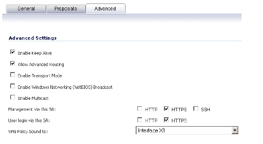
Navigate to the Advanced tab to configure the advanced properties for the Tunnel Interface. By default, Enable Keep Alive is enabled. This is to establish the tunnel with remote gateway proactively.
The following other advanced options can be configured:
Allow Advanced Routing - Adds this Tunnel Interface to the list of interfaces in the Advanced Routing table on the Network > Routing page. By making this an optional setting, this avoids adding all Tunnel Interfaces to the Advanced Routing table, which helps streamline the routing configuration. See Configuring Advanced Routing for Tunnel Interfaces for information on configuring RIP or OSPF advanced routing for the Tunnel Interface.
Enable Transport Mode - Forces the IPsec negotiation to use Transport mode instead of Tunnel Mode. This has been introduced for compatibility with Nortel. When this option is enabled on the local firewall, it MUST be enabled on the remote firewall as well for the negotiation to succeed.
Require authentication of VPN clients by XAUTH - Requires that all inbound traffic on this VPN tunnel is from an authenticated user.
User group for XAUTH users - Specifies the user group that will have access to this VPN if XAUTH is selected
Enable Windows Networking (NetBIOS) Broadcast - Allows access to remote network resources by browsing the Windows® Network Neighborhood.
Enable Multicast - Allows multicast traffic through the VPN tunnel.
Management via this SA - Allows remote users to log in to manage the SonicWALL through the VPN tunnel.
User login via this SA - Allows users to login using the SA.
VPN Policy bound to - Sets the interface the Tunnel Interface is bound to. This is x1 by default.
Creating a Static Route for Tunnel Interface
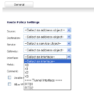
After you have successfully added a Tunnel Interface, you may then create a Static Route. Follow the procedures to create a Static Route for a Tunnel Interface:
Navigate to Network>Routing>Route Policies. Click the Add button. A dialogue window appears for adding Static Route. Note that the “Interface” dropdown menu lists all available tunnel interfaces.
NoteIf the “Auto-add Access Rule” option is selected, firewall rules are automatically added and traffic is allowed between the configured networks using tunnel interface.
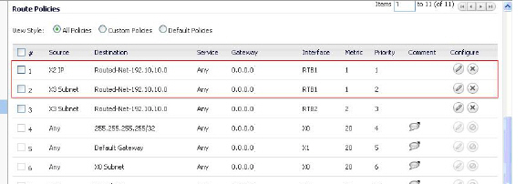
Route Entries for Different Network Segments
After a tunnel interface is created, multiple route entries can be configured to use the same tunnel interface for different networks. This provides a mechanism to modify the network topology without making any changes to the tunnel interface.
The image below shows an example of same tunnel interface for different networks (Routes 1 & 2):
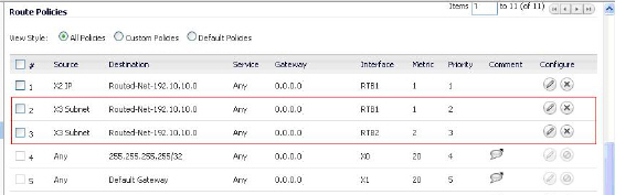
Redundant Static Routes for a Network
After more than one tunnel interface is configured, you can add multiple overlapping static routes; each static route uses a different tunnel interface to route the traffic. This provides routing redundancy for the traffic to reach the destination.
The image below illustrates redundant static routes for a network (Routes 2 & 3):
Drop Tunnel Interface
The drop tunnel interface is a pre-configured tunnel interface. This interface provides added security for traffic. An example of this would be if a static route bind interface is deemed the drop tunnel interface, then all the traffic for that route is dropped and not forwarded in clear. If a static route bind to tunnel interface is defined for traffic (source/destination/service), and it is desired that traffic should not be forwarded in the clear if the tunnel interface is down, it is recommended to configure a static route bind to drop tunnel interface for the same network traffic. As a result, if the tunnel interface is down, traffic will be dropped due to the drop tunnel interface static route.
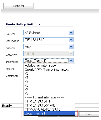
Creating a Static Route for Drop Tunnel Interface
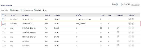
To add a static route for drop tunnel interface, navigate to Network>Routing>Routing Policies. Click the Add button. Similar to configuring a static route for a tunnel interface, configure the values for Source, Destination, and Service Objects. Under Interface, select “Drop_tunnelIf.”
Once added, the route is enabled and displayed in the Route Polices.
VPN Auto-Added Access Rule Control
When adding VPN Policies, SonicOS Enhanced auto-creates non-editable Access Rules to allow the traffic to traverse the appropriate zones. Consider the following VPN Policy, where the Local Network is set to Firewalled Subnets (in this case comprising the LAN and DMZ) and the Destination Network is set to Subnet 192.168.169.0.
While this is generally a tremendous convenience, there are some instances where is might be preferable to suppress the auto-creation of Access Rules in support of a VPN Policy. One such instance would be the case of a large hub-and-spoke VPN deployment where all the spoke site are addresses using address spaces that can easily be supernetted. For example, assume we wanted to provide access to/from the LAN and DMZ at the hub site to one subnet at each of 2,000 remote sites, addressed as follows:
remoteSubnet0=Network 10.0.0.0/24 (mask 255.255.255.0, range 10.0.0.0-10.0.0.255) remoteSubnet1=Network 10.0.1.0/24 (mask 255.255.255.0, range 10.0.1.0-10.0.1.255) remoteSubnet2=Network 10.0.2.0/24 (mask 255.255.255.0, range 10.0.2.0-10.0.2.255) remoteSubnet2000=10.7.207.0/24 (mask 255.255.255.0, range 10.7.207.0-10.7.207.255)
Creating VPN Policies for each of these remote sites would result in the requisite 2,000 VPN Policies, but would also create 8,000 Access Rules (LAN -> VPN, DMZ -> VPN, VPN -> LAN, and VPN -> DMZ for each site). However, all of these Access Rules could easily be handled with just 4 Access Rules to a supernetted or address range representation of the remote sites (More specific allow or deny Access Rules could be added as needed):
remoteSubnetAll=Network 10.0.0.0/13 (mask 255.248.0.0, range 10.0.0.0-10.7.255.255) or remoteRangeAll=Range 10.0.0.0-10.7.207.255
To enable this level of aggregation, the Advanced tab of the VPN Policy window page offers the option to Auto-Add Access Rules for VPN Policy setting. By default, the checkbox is selected, meaning the accompanying Access Rules will be automatically created, as they've always been. By deselecting the checkbox upon creating the VPN Policy, the administrator will have the ability and need to create custom Access Rules for VPN traffic.