Route_Policies
SonicOS provides Policy Based Routing (PBR) to provide more flexible and granular traffic handling capabilities. The following sections describe PBR:
• Probe-Enabled Policy Based Routing Configuration
For general information on routing in SonicOS Enhanced, see Network > Routing.
A simple static routing entry specifies how to handle traffic that matches specific criteria, such as destination address, destination mask, gateway to forward traffic, the interface that gateway is located, and the route metric. This method of static routing satisfies most static requirements, but is limited to forwarding based only on destination addressing.
Policy Based Routing (PBR) allows you to create extended static routes to provide more flexible and granular traffic handling capabilities. SonicOS PBR allows for matching based upon source address, source netmask, destination address, destination netmask, service, interface, and metric. This method of routing allows for full control of forwarding based upon a large number of user defined variables.
A metric is a weighted cost assigned to static and dynamic routes. Metrics have a value between 0 and 255. Lower metrics are considered better and take precedence over higher costs. SonicOS adheres to Cisco defined metric values for directly connected interfaces, statically encoded routes, and all dynamic IP routing protocols.
|
You can change the view your route policies in the Route Policies table by selecting one of the view settings in the View Style menu.
All Policies displays all the routing policies including Custom Policies and Default Policies. Initially, only the Default Policies are displayed in the Route Policies table when you select All Policies from the View Style menu.
The Route Policies table provides easy pagination for viewing a large number of routing policies. You can navigate a large number of routing policies listed in the Route Policies table by using the navigation control bar located at the top right of the Route Policies table. Navigation control bar includes four buttons. The far left button displays the first page of the table. The far right button displays the last page. The inside left and right arrow buttons moved the previous or next page respectively.
You can enter the policy number (the number listed before the policy name in the # Name column) in the Items field to move to a specific routing policy. The default table configuration displays 50 entries per page. You can change this default number of entries for tables on the System > Administration page.
You can sort the entries in the table by clicking on the column header. The entries are sorted by ascending or descending order. The arrow to the right of the column entry indicates the sorting status. A down arrow means ascending order. An up arrow indicates a descending order.
In SonicOS, a static route is configured through a basic route policy. To configure a static route, complete the following steps:
1. Scroll to the bottom of the Network > Routing page and click the Add button. The Add Route Policy window is displayed.
From the Source menu, select the source address object for the static route, or select Create new address object to dynamically create a new address object.
3. From the Destination menu, select the destination address object.
4. From the Service menu, select a service object. For a generic static route that allows all traffic types, simply select Any.
5. From the Gateway menu, select the gateway address object to be used for the route.
6. From the Interface menu, select the interface to be used for the route.
7. Enter the Metric for the route. The default metric for static routes is one. For more information on metrics, see the Policy Based Routing
8. Enter the Comment for the route. This field allows you to enter a descriptive comment for the new static route policy.
9. (Optional) Select the Disable route when the interface is disconnected checkbox to have the route automatically disabled when the interface is disconnected.
10. (Optional) The Allow VPN path to take precedence option allows you to create a backup route for a VPN tunnel. By default, static routes have a metric of one and take precedence over VPN traffic. The Allow VPN path to take precedence option gives precedence over the route to VPN traffic to the same destination address object. This results in the following behavior:
• When a VPN tunnel is active: static routes matching the destination address object of the VPN tunnel are automatically disabled if the Allow VPN path to take precedence option is enabled. All traffic is routed over the VPN tunnel to the destination address object.
• When a VPN tunnel goes down: static routes matching the destination address object of the VPN tunnel are automatically enabled. All traffic to the destination address object is routed over the static routes.
11. The Probe, Disable route when probe succeeds, and Probe default state is UP options are used to configure Probe-Enabled Policy Based Routing. See the following Probe-Enabled Policy Based Routing Configuration for information on their configuration.
12. Click OK to add the route.
Probe-Enabled Policy Based Routing Configuration
When configuring a static route, you can optionally configure a Network Monitor policy for the route. When a Network Monitor policy is used, the static route is dynamically disabled or enabled, based on the state of the probe for the policy.
1. Configure the static route as described in Static Route Configuration.
2. In the Probe pull-down menu select the appropriate Network Monitor object or select Create New Network Monitor object... to dynamically create a new object. For more information, see Network > Network Monitor.
3. Typical configurations will not check the Disable route when probe succeeds checkbox, because typically administrators will want to disable a route when a probe to the route’s destination fails. This option is provided to give administrators added flexibility for defining routes and probes.
4. Select the Probe default state is UP to have the route consider the probe to be successful (i.e. in the “UP” state) when the attached Network Monitor policy is in the “UNKNOWN” state. This is useful to control the probe-based behavior when a unit of a High Availability pair transitions from “IDLE” to “ACTIVE,” because this transition sets all Network Monitor policy states to “UNKNOWN.”
5. Click OK to apply the configuration.
The following example walks you through creating a route policy for two simultaneously active WAN interfaces. For this example, a secondary WAN interface needs to be setup on the X3 interface and configured with the settings from your ISP. Next, configure the security appliance for load balancing by checking the Enable Load Balancing on the Network > WAN Failover & LB page. For this example, choose Per Connection Round-Robin as the load balancing method in the Network > WAN Failover & LB page. Click Accept to save your changes on the Network > WAN Failover & LB page.
1. Click the Add button under the Route Policies table. The Add Route Policy window is displayed.
Create a routing policy that directs all LAN Subnet sources to Any destinations for HTTP service out of the X1 Default Gateway via the X1 interface by selecting these settings from the Source, Destination, Service, Gateway and Interface menus respectively. Use the default 1 in the Metric field and enter force http out primary into the Comment field. Click OK.
3. Create a second routing policy that directs all LAN Subnet sources to Any destinations for Telnet service out of the X3 Default Gateway via the X3 interface by selecting these settings from the Source, Destination, Service, Gateway and Interface menus respectively. Use the default 1 in the Metric field and enter force telnet out backup into the Comment field. Click OK.
Note Do not enable the Allow VPN path to take precedence option for these routing policies. The Allow VPN path to take precedence option gives precedence over the route to VPN traffic to the same destination address object. This option is used for configuring static routes as backups to VPN tunnels. See the Static Route Configuration for more information.
These two policy-based routes force all sources from the LAN subnet to always go out the primary WAN when using any HTTP-based application, and forces all sources from the LAN subnet to always go out the backup WAN when using any Telnet-based application.
To test the HTTP policy-based route, from a computer attached to the LAN interface, access the public Web site http://www.whatismyip.com and http://whatismyip.everdot.org. Both sites display the primary WAN interface’s IP address and not the secondary WAN interface.
To test the Telnet policy-based route, telnet to route-server.exodus.net and when logged in, issue the who command. It displays the IP address (or resolved FQDN) of the WAN IP address of the secondary WAN interface and not the primary WAN interface.
OSPF and RIP Advanced Routing Services
In addition to Policy Based Routing and RIP advertising, SonicOS offers the option of enabling Advanced Routing Services (ARS). Advanced Routing Services provides full advertising and listening support for the Routing Information Protocol (RIPv1 - RFC1058) and (RIPv2 - RFC2453), and Open Shortest Path First (OSPFv2 – RFC2328). Advanced Routing Service should only be enabled by those environments requiring support for either or both of these dynamic routing protocols.
RIP and OSPF are Interior Gateway Protocols (IGP) that are both widely used by networks of various sizes to automate the process of route distribution. RIP is commonly used within smaller networks, while OSPF is used by larger networks, although network size should not be the only factor used to determine the appropriateness of one protocol over the other – network speed, interoperability requirements, and relative overall complexity, for example, should also be considered. RIPv1 and RIPv2 are both supported by ARS, the largest differences between the two being that RIPv2 supports VLSM (Variable Length Subnet Masks), authentication, and routing updates. The following table illustrates the major differences between RIPv1, RIPv2, and OSPFv2:
|
• Protocol Type – Distance Vector protocols such as RIP base routing metrics exclusively on hop counts, while Link state protocols such as OSPF consider the state of the link when determining metrics. For example, OSPF determines interface metrics by dividing its reference bandwidth (100mbits by default) by the interface speed – the faster the link, the lower the cost and the more preferable the path. Consider the following example network:
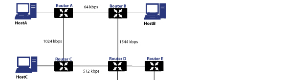
In the above sample network, if Host A wanted to reach Host B, with RIP, the lowest cost route would be from Router A to Router B, across the relatively slow 64kbps link. With OSPF, the cost from Router A to Router B would be 1562, while the cost from Router A to Router C to Router D to Router B would be 364, making it the preferred route.
• Maximum Hops – RIP imposes a hop count of 15 to help prevent routing loops which can occur when bad (e.g. stale) routing information is broadcast and propagated through a network either due to misconfiguration, or slow convergence. Consider if the link between Router D and Router E failed in the diagram above, and there were no safeguards in place:
– Router A’s routing information states that it can reach Network E through Router B or Router C with a metric of 3.
– When the link between Router D and Router E fail, and Router A broadcasts its routing information, Router B and Router C determine that they can reach Network E through Router A with a metric of 4.
– Router B and Router C broadcast this information, and it is received by Router D which then determines it can reach Network E through Router B or Router C with a metric of 5.
– This loop continues until the hop count of 16 (infinity) is reached.
Other measures against this sort of situation are also commonly employed by RIP, including:
• Split-Horizon – A preventative mechanism where routing information learned through an interface is not sent back out the same interface. This generally works well on broadcast links, but not on non-broadcast links such as Frame Relay, where a single link can commonly be used to reach two separate autonomous systems.
• Poison reverse – Also known as route poisoning, an extension of split-horizon where a network is advertised with a metric of 16 (unreachable), helping to ensure that incorrect alternative routes are not propagated.
OSPF does not have to impose a hop count limit because it does not advertise entire routing tables, rather it generally only sends link state updates when changes occur. This is a significant advantage in larger networks in that it converges more quickly, produces less update traffic, and supports an unlimited number of hops.
• Routing table updates – As mentioned above, the practice of sending an entire routing table introduces the problems of slower convergences, higher bandwidth utilization, and increased potential for stale routing information. RIPv1 broadcasts its entire routing table at a prescribed interval (usually every 30 seconds), RIPv2 can either broadcast or multicast, and OSPF multicasts only link state updates whenever a change to the network fabric occurs. OSPF has a further advantage of using designated routers (DR) in forming adjacencies in multiple-access networks (more on these concepts later) so that updates do not have to be sent to the entire network.
• Subnet sizes supported – RIPv1 was first implemented when networks were strictly class A, class B, and class C (and later D and E):
– Class A – 1.0.0.0 to 126.0.0.0 (0.0.0.0 and 127.0.0.0 are reserved)
: •: Leftmost bit 0; 7 network bits; 24 host bits
: •: 0nnnnnnn hhhhhhhh hhhhhhhh hhhhhhhh (8-bit classful netmask)
: •: 126 Class A networks, 16,777,214 hosts each
– Class B - 128.0.0.0 to 191.255.0.0
: •: Leftmost bits 10; 14 network bits; 16 host bits
: •: 10nnnnnn nnnnnnnn hhhhhhhh hhhhhhhh (16-bit classful netmask)
: •: 16,384 Class B networks, 65,532 hosts each
– Class C – 192.0.0.0 to 223.255.255.0
: •: Leftmost bits 110; 21 network bits; 8 host bits
: •: 110nnnnn nnnnnnnn nnnnnnnn hhhhhhhh (24-bit classful netmask)
: •: 2,097,152 Class Cs networks, 254 hosts each
– Class D - 225.0.0.0 to 239.255.255.255 (multicast)
: •: Leftmost bits 1110; 28 multicast address bits
: •: 1110mmmm mmmmmmmm mmmmmmmm mmmmmmmm
– Class E - 240.0.0.0 to 255.255.255.255 (reserved)
: •: Leftmost bits 1111; 28 reserved address bits
: •: 1111rrrr rrrrrrrr rrrrrrrr rrrrrrrr
This method of address allocation proved to be very inefficient because it provided no flexibility, neither in the way of segmentation (subnetting) or aggregation (supernetting, or CIDR – classless inter-domain routing) by means of VLSM – variable length subnet masks.
VLSM, supported by RIPv2 and OSPF, allows for classless representation of networks to break larger networks into smaller networks:
For example, take the classful 10.0.0.0/8 network, and assign it a /24 netmask. This subnetting allocates an additional 16-bits from the host range to the network range (24-8=16). To calculate the number of additional networks this subnetting provides, raise 2 to the number of additional bits: 2^16=65,536. Thus, rather than having a single network with 16.7 million hosts (usually more than most LAN’s require) it is possible to have 65,536 networks, each with 254 usable hosts.
VLSM also allows for route aggregation (CIDR):
For example, if you had 8 class C networks: 192.168.0.0/24 through 192.168.7.0/24, rather than having to have a separate route statement to each of them, it would be possible to provide a single route to 192.168.0.0/21 which would encompass them all.
This ability, in addition to providing more efficient and flexible allocation of IP address space, also allows routing tables and routing updates to be kept smaller.
• Autonomous system topologies – An autonomous system (AS) is a collection of routers that are under common administrative control, and that share the same routing characteristics. When a group of autonomous systems share routing information, they are commonly referred to as a confederation of autonomous systems. (RFC1930 and RFC975 address these concepts in much greater detail). In simple terms, an AS is a logical distinction that encompasses physical network elements based on the commonness of their configurations.
With regard to RIP and OSPF, RIP autonomous systems cannot be segmented, and all routing information must be advertised (broadcast) through the entire AS. This can become difficult to manage and can result in excessive routing information traffic. OSPF, on the other hand, employs the concept of Areas, and allows for logically, manageable segmentation to control the sharing of information within an AS. OSPF areas begin with the backbone area (area 0 or 0.0.0.0), and all other areas must connect to this backbone area (although there are exceptions). This ability to segment the routing AS helps to ensure that it never becomes too large to manage, or too computationally intensive for the routers to handle.
Configuring RIP and OSPF Advanced Routing Services
The following sections describe how to configure advanced routing:
• Configuring Advanced Routing for Tunnel Interfaces
Note ARS is a fully featured multi-protocol routing suite. The sheer number of configurable options and parameters provided is incongruous with the simplicity of a graphical user interface. Rather than limiting the functionality of ARS, an abbreviated representation of its capabilities has been rendered in the GUI, providing control over the most germane routing features, while the full command suite is available via the CLI. The ARS CLI can be accessed from an authenticated CLI session, and contains 3 modules:
• route ars-nsm – The Advanced Routing Services Network Services Module. This component provides control over core router functionality, such as interface bindings and redistributable routes.
• route ars-rip – The RIP module. Provides control over the RIP router.
• route ars-ospf – The OSPF module. Provides control over the OSPF router.
In general, all of the functionality needed to integrate the SonicWALL into most RIP and OSPF environments is available through the Web-based GUI. The additional capabilities of the CLI will make more advanced configurations possible. Please refer to the appendix for the full set of ARS CLI commands.
By default, Advanced Routing Services are disabled, and must be enabled to be made available. At the top of the Network > Routing page, is a pull-down menu for Routing mode. When you select Use Advanced Routing, the top of the Network > Routing page will look as follows:
The operation of the RIP and OSPF routing protocols is interface dependent. Each interface and virtual subinterface can have RIP and OSPF settings configured separately, and each interface can run both RIP and OSPF routers.
Configure RIP and OSPF for default routes received from Advanced Routing protocols as follows: