Network_netInterfaces
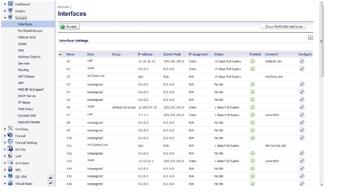
The Network > Interfaces page includes interface objects that are directly linked to physical interfaces. The SonicOS scheme of interface addressing works in conjunction with network zones and address objects.

This chapter contains the following sections:
• Interface Traffic Statistics
• Physical and Virtual Interfaces
• Configuring IPS Sniffer Mode
• Configuring Wire and Tap Mode
• Configuring Layer 2 Bridge Mode
The Interface Settings table lists the following information for each interface:
• Name - The name of the interface.
• Zone - LAN, WAN, DMZ, and WLAN are listed by default. As zones are configured, the names are listed in this column.
• Group - If the interface is assigned to a Load Balancing group, it is displayed in this column.
• IP Address - IP address assigned to the interface.
• Subnet Mask - The network mask assigned to the subnet.
• IP Assignment - The available methods of IP assignment depend on which zone the interface is assigned to:
– LAN: Static, Transparent, Layer 2 Bridged Mode, Wire Mode, Tap mode.
– WAN: Static, DHCP, PPPoE, PPTP, L2TP
– DMZ: Static, Transparent, Layer 2 Bridged Mode, PortShield
– WLAN: Static, Layer 2 Bridged Mode, PortShield
Status - the link status and speed.
• Comment - any user-defined comments.
• Configure - click the Configure icon ![]() to display the Edit Interface window, which allows you to configure the settings for the specified interface.
to display the Edit Interface window, which allows you to configure the settings for the specified interface.
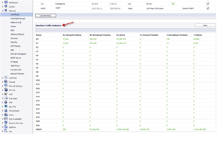
When you scroll down the Network > Interfaces page, the Interface Traffic Statistics table appears, which lists received and transmitted information for all configured interfaces.

The following information is displayed for each interface:
• Rx Unicast Packets - indicates the number of point-to-point communications received by the interface.
• Rx Broadcast Packets - indicates the number of multipoint communications received by the interface.
• RX Bytes - indicates the volume of data, in bytes, received by the interface.
• Tx Unicast Packets - indicates the number of point-to-point communications transmitted by the interface.
• Tx Broadcast Bytes - indicates the number of mutlipoint communications received by the interface.
• Tx Bytes - indicates the volume of data, in bytes, transmitted by the interface.
To clear the current statistics, click the Clear button at the top right of the Network > Interfaces page.
Physical and Virtual Interfaces
Interfaces in SonicOS can be:
• Physical interfaces – Physical interfaces are bound to a single port
• Virtual interfaces – Virtual interfaces are assigned as subinterfaces to a physical interface and allow the physical interface to carry traffic assigned to multiple interfaces.
• PortShield interfaces – Any number of the LAN ports on these appliances can be combined into a single PortShield interface.
Physical Interfaces
Physical interfaces must be assigned to a zone to allow for configuration of Access Rules to govern inbound and outbound traffic. Security zones are bound to each physical interface where it acts as a conduit for inbound and outbound traffic. If there is no interface, traffic cannot access the zone or exit the zone.
For more information on zones, see Network > Zones.
Virtual Interfaces (VLAN)
Supported on SonicWALL security appliances, virtual Interfaces are subinterfaces assigned to a physical interface. Virtual interfaces allow you to have more than one interface on one physical connection.
Virtual interfaces provide many of the same features as physical interfaces, including zone assignment, DHCP Server, and NAT and Access Rule controls.
Virtual Local Area Networks (VLANs) can be described as a ‘tag-based LAN multiplexing technology’ because through the use of IP header tagging, VLANs can simulate multiple LAN’s within a single physical LAN. Just as two physically distinct, disconnected LAN’s are wholly separate from one another, so too are two different VLANs, however the two VLANs can exist on the very same wire. VLANs require VLAN aware networking devices to offer this kind of virtualization – switches, routers and firewalls that have the ability to recognize, process, remove and insert VLAN tags in accordance with the network’s design and security policies.
VLANs are useful for a number of different reasons, most of which are predicated on the VLANs ability to provide logical rather than physical broadcast domain, or LAN boundaries. This works both to segment larger physical LAN’s into smaller virtual LAN’s, as well as to bring physically disparate LAN’s together into a logically contiguous virtual LAN. The benefits of this include:
• Increased performance – Creating smaller, logically partitioned broadcast domains decreases overall network utilization, sending broadcasts only where they need to be sent, thus leaving more available bandwidth for application traffic.
• Decreased costs – Historically, broadcast segmentation was performed with routers, requiring additional hardware and configuration. With VLANs, the functional role of the router is reversed – rather than being used for the purposes of inhibiting communications, it is used to facilitate communications between separate VLANs as needed.
• Virtual workgroups – Workgroups are logical units that commonly share information, such as a Marketing department or an Engineering department. For reasons of efficiency, broadcast domain boundaries should be created such that they align with these functional workgroups, but that is not always possible: Engineering and Marketing users might be commingled, sharing the same floor (and the same workgroup switch) in a building, or just the opposite – the Engineering team might be spread across an entire campus. Attempting to solve this with complex feats of wiring can be expensive and impossible to maintain with constant adds and moves. VLANs allow for switches to be quickly reconfigured so that logical network alignment can remain consistent with workgroup requirements.
• Security – Hosts on one VLAN cannot communicate with hosts on another VLAN unless some networking device facilitates communication between them.
Subinterfaces
VLAN support on SonicOS is achieved by means of subinterfaces, which are logical interfaces nested beneath a physical interface. Every unique VLAN ID requires its own subinterface. For reasons of security and control, SonicOS does not participate in any VLAN trunking protocols, but instead requires that each VLAN that is to be supported be configured and assigned appropriate security characteristics.
Note Dynamic VLAN Trunking protocols, such as VTP (VLAN Trunking Protocol) or GVRP (Generic VLAN Registration Protocol), should not be used on trunk links from other devices connected to the SonicWALL.
Trunk links from VLAN capable switches are supported by declaring the relevant VLAN ID’s as a subinterface on the SonicWALL, and configuring them in much the same way that a physical interface would be configured. In other words, only those VLANs which are defined as subinterfaces will be handled by the SonicWALL, the rest will be discarded as uninteresting. This method also allows the parent physical interface on the SonicWALL to which a trunk link is connected to operate as a conventional interface, providing support for any native (untagged) VLAN traffic that might also exist on the same link. Alternatively, the parent interface may remain in an ‘unassigned’ state.
VLAN subinterfaces have most of the capabilities and characteristics of a physical interface, including zone assignability, security services, GroupVPN, DHCP server, IP Helper, routing, and full NAT policy and Access Rule controls. Features excluded from VLAN subinterfaces at this time are WAN dynamic client support and multicast support. The following table lists the maximum number of subinterfaces supported on each platform.
|
The SonicOS scheme of interface addressing works in conjunction with network zones and address objects. This structure is based on secure objects, which are utilized by rules and policies within SonicOS.
Secured objects include interface objects that are directly linked to physical interfaces and managed in the Network > Interfaces page. Address objects are defined in the Network > Address Objects page. Service and Scheduling objects are defined in the Firewall section of the SuperMassive Management Interface, and User objects are defined in the Users section of the SuperMassive Management Interface.
Zones are the hierarchical apex of SonicOS’s secure objects architecture. SonicOS includes predefined zones as well as allow you to define your own zones. Predefined zones include LAN, DMZ, WAN, WLAN, and Custom. Zones can include multiple interfaces, however, the WAN zone is restricted to a total of two interfaces. Within the WAN zone, either one or both WAN interfaces can be actively passing traffic depending on the WAN Failover and Load Balancing configuration on the Network > WAN Failover & LB page.
For more information on WAN Failover and Load Balancing on the SuperMassive, see Network > Failover & Load Balancing.
At the zone configuration level, the Allow Interface Trust setting for zones automates the processes involved in creating a permissive intra-zone Access Rule. It creates a comprehensive Address Object for the entire zone and a inclusively permissive Access Rule from zone address to zone addresses.
Transparent Mode in SonicOS uses interfaces as the top level of the management hierarchy. Transparent Mode supports unique addressing and interface routing.
Supported on SuperMassives, IPS Sniffer Mode is a variation of Layer 2 Bridge Mode that is used for intrusion detection. IPS Sniffer Mode configuration allows an interface on the SonicWALL to be connected to a mirrored port on a switch to examine network traffic. Typically, this configuration is used with a switch inside the main gateway to monitor traffic on the intranet.
In the network diagram below, traffic flows into a switch in the local network and is mirrored through a switch mirror port into a IPS Sniffer Mode interface on the SuperMassive. The SonicWALL inspects the packets according to the settings configured on the Bridge-Pair. Alerts can trigger SNMP traps which are sent to the specified SNMP manager via another interface on the SonicWALL. The network traffic is discarded after the SonicWALL inspects it.
The WAN interface of the SonicWALL is used to connect to the SonicWALL Data Center for signature updates or other data.

In IPS Sniffer Mode, a Layer 2 Bridge is configured between two interfaces in the same zone on the SonicWALL, such as LAN-LAN or DMZ-DMZ. You can also create a custom zone to use for the Layer 2 Bridge. Only the WAN zone is not appropriate for IPS Sniffer Mode.
The reason for this is that SonicOS detects all signatures on traffic within the same zone such as LAN-LAN traffic, but some directional specific (client-side versus server-side) signatures do not apply to some LAN-WAN cases.
Either interface of the Layer 2 Bridge can be connected to the mirrored port on the switch. As network traffic traverses the switch, the traffic is also sent to the mirrored port and from there into the SonicWALL for deep packet inspection. Malicious events trigger alerts and log entries, and if SNMP is enabled, SNMP traps are sent to the configured IP address of the SNMP manager system. The traffic does not actually continue to the other interface of the Layer 2 Bridge. IPS Sniffer Mode does not place the appliance inline with the network traffic, it only provides a way to inspect the traffic.
The Edit Interfaces page available from the Network > Interfaces page provides a new checkbox called Only sniff traffic on this bridge-pair for use when configuring IPS Sniffer Mode. When selected, this checkbox causes the SonicWALL to inspect all packets that arrive on the L2 Bridge from the mirrored switch port. The Never route traffic on this bridge-pair checkbox should also be selected for IPS Sniffer Mode to ensure that the traffic from the mirrored switch port is not sent back out onto the network.
For detailed instructions on configuring interfaces in IPS Sniffer Mode, see Configuring IPS Sniffer Mode.
Sample IPS Sniffer Mode Topology
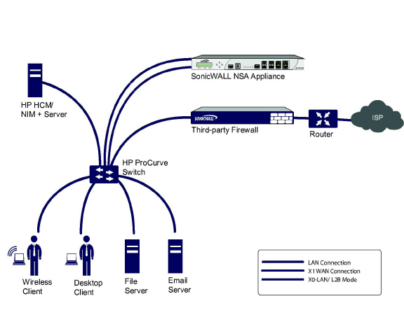
This section provides an example topology that uses SonicWALL IPS Sniffer Mode in a Hewlett Packard ProCurve switching environment. This scenario relies on the ability of HP’s ProCurve Manager Plus (PCM+) and HP Network Immunity Manager (NIM) server software packages to throttle or close ports from which threats are emanating.
This method is useful in networks where there is an existing firewall that will remain in place, but you wish to use the Dell SonicWALL network security appliance services as a sensor.

In this deployment the WAN interface and zone are configured for the internal network’s addressing scheme and attached to the internal network. The X2 port is Layer 2 bridged to the LAN port – but it won’t be attached to anything. The X0 LAN port is configured to a second, specially programmed port on the HP ProCurve switch. This special port is set for mirror mode – it will forward all the internal user and server ports to the “sniff” port on the SonicWALL. This allows the SonicWALL to analyze the entire internal network’s traffic, and if any traffic triggers the SonicWALL signatures, it will immediately trap out to the PCM+/NIM server via the X1 WAN interface, which then can take action on the specific port from which the threat is emanating.
To configure this deployment, navigate to the Network > Interfaces page and click the configure icon for the X2 interface. On the X2 Settings page, set the IP Assignment to ‘Layer 2 Bridged Mode’ and set the Bridged To: interface to ‘X0’. Select the checkbox for Only sniff traffic on the bridge-pair. Click OK to save and activate the change.
Next, go to the Network > Interfaces page and click the configure icon for the X1 WAN interface. On the X1 Settings page, assign it a unique IP address for the internal LAN segment of your network – this may sound wrong, but this will actually be the interface from which you manage the appliance, and it is also the interface from which the appliance sends its SNMP traps as well as the interface from which it gets SonicWALL signature updates. Click OK.
You must also modify the firewall rules to allow traffic from the LAN to WAN, and from the WAN to the LAN, otherwise traffic will not pass successfully.
Connect the span/mirror switch port to X0 on the SonicWALL, not to X2 (in fact X2 isn’t plugged in at all), and connect X1 to the internal network. Use care when programming the ports that are spanned/mirrored to X0.