Configuring Network DHCP and Interface Settings
When Active/Active Clustering is enabled, the SonicOS internal DHCP server is turned off and cannot be enabled. Networks needing a DHCP server can use an external DHCP server. The SonicOS DHCP server should be disabled in the management interface before enabling Active/Active Clustering, and all DHCP server lease scopes deleted.
On the Network > Interfaces page, you can configure additional virtual IP addresses for interfaces in a Virtual Group, and redundant ports for interfaces.
For information about performing these tasks, see the following sections:
• Disabling the SonicOS DHCP Server
• Configuring Virtual IP Addresses
Disabling the SonicOS DHCP Server
To disable the SonicOS DHCP server and delete all DHCP server lease scopes, perform the following steps:
1. Login to the Primary unit of the Cluster Node and navigate to the Network > DHCP Server page.
2. Clear the Enable DHCP Server checkbox.
3. Under DHCP Server Lease Scopes, select the checkbox at the top left corner of the table heading to select all lease scopes in the table.

4. Click the Delete All button.
5. Click OK in the confirmation dialog box.
6. Click Accept at the top of the Network > DHCP Server page.
Configuring Virtual IP Addresses
When Active/Active Clustering is enabled for the first time, the configured IP addresses for the interfaces on that firewall are automatically converted to virtual IP addresses for Virtual Group 1. Thus, Virtual Group 1 will include virtual IP addresses for X0, X1, and any other interfaces which are configured and assigned to a zone.
Active/Active Clustering requires additional configuration of virtual IP addresses for additional Virtual Groups. You can assign multiple virtual IP addresses to each interface, one per Virtual Group. Each additional virtual IP address is associated with one of the other Virtual Groups in the cluster. Each interface can have up to a maximum of four virtual IP addresses. VLAN interfaces can also have up to four virtual IP addresses.
Note A packet cannot be forwarded on an interface if a virtual IP address is not configured on it for the Virtual Group handling that traffic flow.
To configure a virtual IP address on an interface:
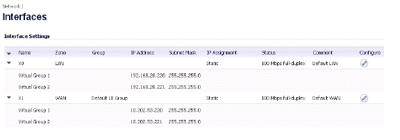
1. Login to the Primary unit of the Cluster Node and navigate to the Network > Interfaces page.
2. In the Interface Settings table, click the configure icon for the interface you want to configure.
3. In the Edit Interface window, type the virtual IP address into the IP Address (Virtual Group X) field, where ‘X’ is the virtual group number.
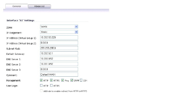
Note The new virtual IP address must be in the same subnet as any existing virtual IP address for that interface.
4. Click OK. The configured virtual IP address appears in the Interface Settings table.
Redundant ports can be used along with Active/Active Clustering. You can assign an unused physical interface as a redundant port to a configured physical interface called the “primary interface”. If there is a physical link failure on the primary interface, the redundant interface can continue processing traffic without any interruption. One advantage of this feature is that in case of a physical link failure, there is no need to do a device failover.
You can configure a redundant port on the Advanced tab of the Edit Interface window. The Redundant Port field is only available when Active/Active Clustering is enabled.
Note Because all Cluster Nodes share the same configuration, each node must have the same redundant ports configured and connected to the same switch(es).
For information about physically connecting redundant ports and redundant switches, see the Active/Active Clustering Full Mesh Deployment Technote.
To configure a redundant port for an interface:
1. Login to the Primary unit of the Cluster Node and navigate to the Network > Interfaces page.
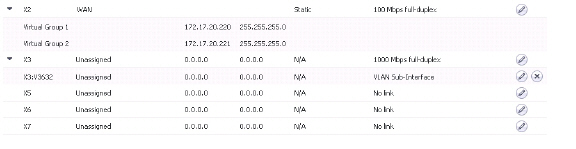
2. In the Interface Settings table, click the configure icon for the primary interface for which you want to create a redundant port.
For example, click the configure icon for X2.
In the Edit Interface window, click the Advanced tab.
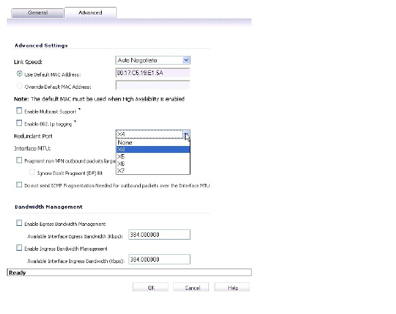
4. In the Redundant Port field, select the redundant port from the drop-down list. Only unused interfaces are available for selection.
For example, select X4 for the redundant port.
5. Click OK.
The selected interface will be greyed-out in the Interface Settings table. A note indicates that it is a redundant Port and lists the primary interface. The interface also appears in the Redundant Port field in the Edit Interface window of the primary port.
Note The primary and redundant ports must be physically connected to the same switch, or preferably, to redundant switches in the network.
6. On each Cluster Node, replicate the redundant physical connections using the same interface numbers for primary and redundant ports. All Cluster Nodes share the same configuration as the Master node.
Active/Active Clustering Full-Mesh
This section contains the following subsections:
• Active/Active Clustering Full-Mesh Overview
• Configuring Active/Active Clustering Full Mesh
• Configuring Active/Active Cluster Full-Mesh 2-Unit Deployment
Active/Active Clustering Full-Mesh Overview
Active/Active Clustering Full-Mesh configuration is an enhancement to the Active/Active Clustering configuration option and prevents any single point of failure in the network. All firewall and other network devices are partnered for complete redundancy. Full-Mesh ensures that there is no single point of failure in your deployment, whether it is a device (firewall/switch/router) or a link. Every device is wired twice to the connected devices. Active/Active Clustering with Full-Mesh provides the highest level of availability possible with high performance.
Note The routers in the firewall’s upstream network should be pre-configured for Virtual Router Redundancy Protocol (VRRP).
Active/Active Clustering Full Mesh configuration is an enhancement to the Active/Active Clustering configuration option and provides the highest level of availability possible with high performance. Full Mesh deployments provide a very high level of availability for the network, because all devices have one or more redundant partners, including routers, switches, and security appliances. Every device is wired twice to the connected devices, so that no single point of failure exists in the entire network. For example, every SonicWALL firewall uses redundant ports to connect twice to each networking device.
Note Full Mesh deployments require that Port Redundancy is enabled and implemented.
Benefits of Active/Active Clustering Full Mesh
The following are key benefits to this deployment configuration:
• No Single Point of Failure in the Core Network: In an Active/Active Clustering Full-Mesh deployment, there is no single point of failure in the entire core network, not just for the firewalls. An alternative path for a traffic flow is always available in case there are simultaneous failures of switch, router, firewall on a path, thus providing the highest levels of availability.
• Port Redundancy: Active/Active Clustering Full-Mesh utilizes port redundancy in addition to HA redundancy within each Cluster Node, and node level redundancy within the cluster. With port redundancy, a backup link will take over in a transparent manner if the primary port fails. This prevents the need for device level failover.
Redundant Ports and Redundant Switches
Redundant ports can be used along with Active/Active Clustering. If one port should have a fault, the traffic is seamlessly handled through the redundant port without causing an HA or Active/Active failover. A Redundant Port field in the Network > Interfaces > Edit Interface page becomes available when Active/Active Clustering is enabled.
When configuring a redundant port, the interface must be unused; that is, not assigned to any zone. The two ports must be physically connected to the same switch, or preferably, to redundant switches in the network.
Note Because all Cluster Nodes shares the same configuration, each node must have the same redundant ports configured and connected to the same switch(es).
While all Cluster Nodes are up and processing traffic normally, redundant ports remain standby and are ready for use if the partner port goes down for any reason. If one Cluster Node goes down, causing an Active/Active failover, the redundant port on the remaining Cluster Node is put to use immediately to handle the traffic for the Virtual Group that was owned by the failed node. This provides load sharing.
For example, say we have a deployment in which Virtual Group 1 is owned by Cluster Node 1 and Virtual Group 2 is owned by Cluster Node 2. The Cluster Nodes are configured with redundant ports, X3 and X4. No traffic is sent on X4 while all nodes are functioning properly. If Cluster Node 2 goes down, Virtual Group 2 is now also owned by Cluster Node 1. At this point, the redundant port X4 begins to be used for load sharing. Virtual Group 1 traffic is sent on X3, while Virtual Group 2 traffic is sent on X4. In a larger deployment, if Cluster Node 1 owns three or four Virtual Groups, traffic is distributed among the redundant ports – traffic for Virtual Groups 1 & 3 is sent on X3, while traffic for Virtual Groups 2 & 4 is sent on X4.
When a redundant switch is configured, SonicWALL recommends using a redundant port to connect to it. While it is possible to connect a redundant switch without using a redundant port, this involves complex configuration using probes. A redundant switch can be deployed anywhere in the network depending on the need for high availability. For example, a redundant switch might be deployed on the WAN side if traffic passing through it is business-critical.
This diagram shows a deployment that includes redundant routers, switches, and ports on the WAN side, but is not a Full Mesh deployment because the LAN side does not use redundancy.
Figure 54:27 WAN Side Redundancy
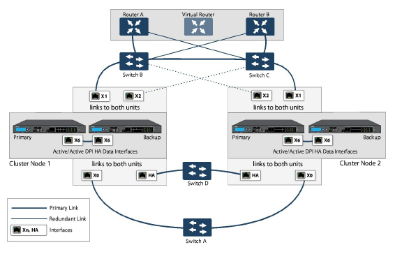
Full Mesh is not required when deploying redundant ports or switches, but a Full Mesh deployment includes them. A Full Mesh deployment uses redundant ports on each of the main traffic ports (LAN, WAN, etc.), and uses redundant upstream routers in addition to redundant switches.
For more information about Full Mesh deployments, see the Active/Active Clustering Full Mesh Deployment Technote.
Configuring Active/Active Clustering Full Mesh
This section describes the procedure for setting up an Active/Active Cluster Full-Mesh deployment. It describes a 4 unit Active/Active Clustering Full-Mesh setup. We will go over the following aspects of the deployment:
• Cabling for Active/Active Full Mesh
• Configuring Active/Active Cluster Firewalls
• Configuring Active/Active Cluster Full-Mesh 2-Unit Deployment
The deployments described are examples. Your actual deployment might differ based on the following factors:
• Topology/design of your network and the types of network devices you use (switches, routers, load balancers, etc)
• Level of availability desired
• Resource constraints
Figure 54:28 Active/Active Four-Unit Cluster Full Mesh
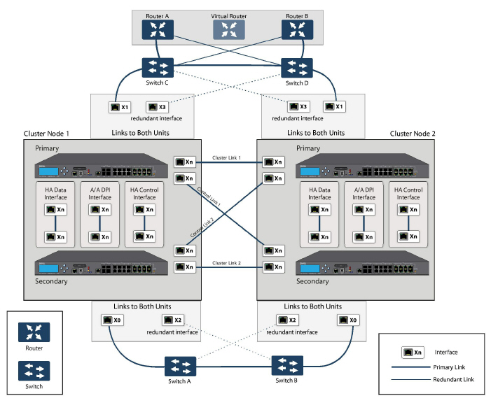
Cabling for Active/Active Full Mesh
This procedure describes the cabling for the deployment illustrated in the above diagram.
To physically connect your network devices for a full-mesh deployment, perform the following steps:
1. Connect all the HA links of all the firewalls into a port-based-VLAN on Switch E.
2. In the setup described above, X2 is the redundant port of X0. Connect the cables as follows for the X0, X2 ports:
a. Connect CN2-Primary Firewall’s X0 to Switch A and X2 to Switch B.
b. Connect CN2-Backup Firewall’s X0 to Switch A and X2 to Switch B.
c. Connect CN2-Primary Firewall’s X0 to Switch B and X2 to Switch A.
d. Connect CN2-Backup Firewall’s X0 to Switch B and X2 to Switch A.
3. On Switch A and Switch B:
a. Configure all the Switch ports connected to the X0,X2 interfaces to be in the same port-based VLAN.
b. Enable Spanning Tree, but also enable Port Fast (or equivalent command) on the ports connected to the firewalls.
4. In the setup described above, X3 is the redundant port of X1. Connect the cables as follows for the X1, X3 ports:
a. Connect CN2-Primary Firewall’s X1 to Switch C and X3 to Switch D.
b. Connect CN2-Backup Firewall’s X1 to Switch C and X3 to Switch D.
c. Connect CN2-Primary Firewall’s X1 to Switch D and X3 to Switch C.
d. Connect CN2-Backup Firewall’s X1 to Switch D and X3 to Switch C.
5. On Switch C and Switch D:
a. Configure all the Switch ports connected to the X1,X3 interfaces to be in the same port-based VLAN.
b. Enable Spanning Tree, but also enable Port Fast (or equivalent command) on the ports connected to the firewalls.
6. Cable Switch A and Switch B together.
7. Cable Switch C and Switch D together.
8. If the Router A and Router B have redundant port support, then connect the Routers to Switches in the same way as we connected the Firewall ports to Switches. That is, connect the primary port on Router A to Switch C and the backup port on Router A to Switch D. Connect the ports in the same way for Router B.
9. If the Routers do not have redundant port support, but have switching support then you create two ports in the same VLAN on Router A and assign an IP address to the VLAN instead of the port. Then connect one port to Switch C and the other port to Switch D. Do a similar configuration for Router B. (This is the setup shown in the diagram).
10. In the setup described above, we also use Active/Active DPI along with Active/Active Clustering. Ports X6 and X7 are the two HA data ports for redundancy and load-sharing of offloaded traffic from Active to Standby firewalls. Perform the following cabling (X6,X7 ports and cabling have not been shown in the above diagram for brevity):
a. Connect X6 of CN1-Primary to X6 of CN1-Backup with a Cross-over cable.
b. Connect X7 of CN1-Primary to X7 of CN1-Backup with a Cross-over cable.
c. Connect X6 of CN2-Primary to X6 of CN2-Backup with a Cross-over cable.
d. Connect X7 of CN2-Primary to X7 of CN2-Backup with a Cross-over cable.
Configuring Active/Active Cluster Firewalls
This section describes the steps to configure the Active/Active Cluster firewalls.
1. Shut down all firewalls except the CN1-Primary unit.
2. On the High Availability > Settings page:
a. Choose Active/Active Clustering mode.
b. Enter the Cluster Node serial numbers.
c. Select CN1 as Owner for Virtual Group 1 and Standby for Virtual Group 2.
d. Select CN2 as Owner for Virtual Group 2 and Standby for Virtual Group 1.
e. Enable Stateful Synchronization.
f.: Enable Active/Active DPI with X6 and X7 as the two HA data ports.
g. Click Submit.
3. On the Network > Interfaces page:
a. Add the Virtual Group (VG) IP addresses for both the X0 and X1 interfaces.
b. Add the redundant port configuration (X2 as redundant port of X0, X3 as redundant port of X1).
4. On the High Availability > Monitoring page, add the monitoring/management IP addresses either on X0 or X1 for each unit in the cluster.
5. Turn on all the other firewalls. A complete synchronization of the configuration is made from the CN1-Primary to all other firewalls.
6. Login to each firewall unit using the dedicated monitoring/management address and do the following:
a. Register the firewall on MySonicWALL.
b. Synchronize the licenses with MySonicWALL.
Testing for No Point of Failure
After the above deployment is connected and configured, CN1 will own Virtual Group1 (VG1), and CN2 will own Virtual Group 2 (VG2).
Configure the VG1 IP address on X0 as the gateway for a certain set of traffic flows and the VG2 IP address on X0 as the gateway for other sets of traffic flows. The network administrator can use different methods to accomplish this. One way is to use a smart DHCP server which distributes the gateway allocation to the PCs on the directly connected client network. Another method is by using policy based routes on a downstream router.
When the traffic setup is done, both Cluster Nodes will actively process network traffic. Now we can test for no single point of failure on all devices and links with the following steps:
1. Device Failures: Traffic should continue to flow through both Cluster Nodes in each of the following device failures:
a. Power down Switch A while Switch B is up and ready.
b. Power down Switch B while Switch A is up and ready.
c. Restart the Active unit in CN1 from the SonicOS management interface while the Standby unit in CN1 is up and ready (this scenario is similar to a software failure on the CN1-Active unit). Note that there will be a Stateful HA failover in this case.
d. Shut down the CN1-Active unit while the CN1-Standby unit is up and ready (this scenario is similar to a hardware failure on the CN1-Active unit). Note that there will be a Stateful HA failover in this case.
e. Repeat steps c) and d) for CN2.
f.: Shut down Router A while Router B is up and ready.
g. Shut down Router B while Router A is up and ready.
2. Link Failures: Traffic should continue to flow in each of the following link failures:
a. On each of the Active firewalls in the Cluster Node, disconnect the X0 cable while X2 is connected.
b. On each of the Active firewalls in the Cluster Node, disconnect the X1 cable while X3 is connected.
c. Disconnect the primary link from upstream switches to the router which is the Active virtual router.
d. Disconnect X6, the Active-Active DPI HA data interface.
Configuring Active/Active Cluster Full-Mesh 2-Unit Deployment
In previous sections we discussed the Active/Active Cluster Full-Mesh with 4 firewall units. Optionally, you can deploy Active/Active Cluster Full-Mesh with 2 firewall units where each CN consists of only one firewall (no HA backup). However, such a setup has the following limitations:
• Failover will not be stateful and existing connections will need to be re-built.
• If the traffic on each unit is greater than 50% of the capacity of the single unit at the time of failover, then after the failover the traffic in excess of 50% will be dropped.
The procedure for the 2-unit Full-Mesh is similar to the procedure for the 4-unit Full-Mesh, with the following exceptions:
• The steps involving the Backup unit in each node do not apply.
• The steps for configuring Stateful Sync and Active-Active DPI do not apply.
• There is no Switch required for connecting the HA ports (since there are only two, they can be directly connected with a cross over cable).