IPv6
This appendix provides an overview of the SonicOS implementation of IPv6, how IPv6 operates, and how to configure IPv6 for your network. This appendix contains the following sections:
• IPv6 High Availability Monitoring
• IPv6 Diagnostics and Monitoring
The following sections provide an overview of IPv6:
• Dell SonicWALL IPv6 Feature Support
• Dell SonicWALL IPv6 Features Not Currently Supported
![]()
Dell SonicWALL has met the requirements for "IPv6 Ready" Phase-1 and Phase-2, as specified by the IPv6 Forum, a world-wide consortium providing technical guidance for the deployment of IPv6. The IPv6 Ready Logo Program is a conformance and interoperability testing program intended to increase user confidence by demonstrating that IPv6 is available now and ready to be used.
The IPv6 Ready series of tests extends from a basic level of minimum coverage in Phase-1 to a more complete coverage with Phase-2:
• Phase-1 (Silver) Logo: In a first stage, the Logo indicate that the product includes IPv6 mandatory core protocols and can interoperate with other IPv6 implementations.
• Phase-2 (Gold) Logo: The "IPv6 ready" step implies a proper care, technical consensus and clear technical references. The IPv6 Ready Logo will indicate that a product has successfully satisfied strong requirements stated by the IPv6 Logo Committee (v6LC).
Dell SonicWALL has been certified for Phase 2 (Gold) IPv6 Ready status. A future Phase-3 level of IPv6 Ready coverage is currently being developed.
For more information, see: http://www.ipv6ready.org/
Note Wizards for IPv6 are not supported in SonicOS.
Every device that is connected to the Internet (computer, printer, smart phone, smart meter, etc.) requires an IP address. The Internet Protocol version 4 (IPv4) provides for approximately 4.3 billion unique IP addresses. The rapid global expansion in usage of the Internet, mobile phones, and VoIP telephony will soon lead to the exhaustion of these 4.3 billion IP addresses.
On February 3rd, 2011, the Internet Assigned Numbers Authority (IANA) distributed the last-remaining blocks of IPv4 addresses to the Regional Internet Registries (RIRs). After the RIRs distribute these addresses to ISPs later this year, the world’s supply of new IPv4 addresses will be exhausted.
Luckily, the Internet Engineering Task Force (IETF) began planning for this day back around 1992, and in 1998, RFC 2460 was published to define Internet Protocol, Version 6 (IPv6). By increasing the address length from 32 bits to 128 bits, IPv6 dramatically increases the number of available addresses compared to IPv4:
• IPv4: 4,294,967,296 addresses
• IPv6: 340,282,366,920,938,463,463,374,607,431,768,211,456 addresses
Understanding IPv6 Addresses
IPv6 addresses are written in eight groups of four hexadecimal digits separated by colons, in the form:
XXXX:XXXX:XXXX:XXXX:XXXX:XXXX:XXXX:XXXX
IPv6 addresses are logically divided into two parts: a 64-bit (sub-)network prefix, and a 64-bit interface identifier. Here is an example of an IPv6 address:
2001:0db8:85a3:0000:0000:8a2e:0370:7334
Note The hexadecimal digits in IPv6 addresses are case-insensitive.
IPv6 address can be abbreviated using the following two rules:
1. Leading zeroes within a 16-bit value may be omitted. Thus, our example address can be abbreviated from the full form:
– 2001:0db8:85a3:0000:0000:8a2e:0370:7334
to this abbreviated form:
– 2001:db8:85a3:0:0:8a2e:370:7334
2. Any number of consecutive groups of four zeros (technically 16-bits of zeros) can be expressed by a double colon (the “::” symbol). Combing these two rules, our example address can be abbreviated from the full form:
– 2001:0db8:85a3:0000:0000:8a2e:0370:7334
to this abbreviated form:
– 2001:db8:85a3::8a2e:370:7334
|
Note Networks must have IPv4 internet connectivity to get connected to IPv6 internet.
Note IPv6 stack must be enabled for computers at the local network sites.
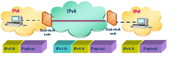
Here is a simplified picture showing connectivity model for a typical IPv6 deployment.
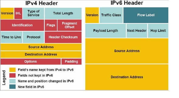
The following diagram shows a comparison of the header elements between IPv4 and IPv6.
IPv6 brings some key features to improve the limitations exposed by IPv4. The new IP standard extends IPv4 in a number of important aspects:
• 6to4 tunnel (allows IPv6 nodes to connect to outside IPv6 services over an IPv4 network)
– 6to4 Auto Tunnel
– GRE Tunnel
• IPv6 Manual Tunnel
• New, simplified IPv6 header format
• Massively large number of available IPv6 addresses
• Efficient and hierarchical addressing and routing infrastructure
• Auto address assignment to hosts and routers using Neighbor Discovery Protocol (NDP) and DHCPv6
• Stateless and stateful address configuration
• Built-in security - AH and ESP strongly recommended
• Better support for QoS - Flow label in the header
• New protocol for neighboring node interaction
• Extensibility for new features using extension headers
Dell SonicWALL IPv6 Feature Support
The following is a list of IPv6 services and features that are currently supported by Dell SonicWALL:
• Access Rules
• Address Objects
• Advanced Bandwidth Management:
– Bandwidth Management Monitor
• Anti-Spyware
• App Flow Server:
– IPv6 App Flow generating to App Flow Server
– IPv6 App Flow generating to 3rd party App Flow Server
• Application Firewall:
– App Rules
• Attack prevention:
– Land Attack
– MAC Anti-spoof
– Ping of Death
– Smurf
– SYN Flood
• Client Anti-Virus Enforcement
• Connection Cache
• Connection Monitor:
– IPv6 Address Filtering
• Content Filtering:
– ActiveX, Java, Cookies Restriction
– CFS Custom List
– CFS Exclusion List
– Content Filtering Service
– Keywords Blocking
• DHCP:
– DHCP Server
– Dynamic Lease Scope
– Generic Options
– Integrated Options (DNS/WINS Server)
– Lease Persistence
– Static Lease Scope
• Diagnostics:
– Nslookup
– Ping6
– Reverse Nslookup
– Traceroute
• DNS client
• DNS lookup and reverse name lookup
• Dual Stack IPv4 and IPv6
• EPRT
• EPSV
• FTPv6
• Flood Protection:
– TCP Sync Proxy
• Fragmentation Handling
• Gateway Anti-Virus
• Header Validation
• High Availability:
– Connection Cache
– DHCP Server
– FTP
– Monitoring IP
– NDP
– SonicPoint
– ULAv6
– VPN
• HTTP/HTTPS management over IPv6
• ICMPv6
• IDP
• IKEv2
• Interface:
– DHCP Client Mode
– IPv6 Interface
– Layer 2 Bridged Mode
– PPPoE Client Mode
– Wire Mode
• Intrusion Prevention Service
• IP Spoof Protection
• IPv4 Syslog messages, including messages with IPv6 addresses
• IPv6 Connection Limit
• ISATAP
• Layer 2 Bridge Mode
• Log:
– IPv6 Address Log Entry
• Logging IPv6 events
• Login uniqueness
• Multicast Routing with Multicast Listener Discovery
• NAT
• NAT load balancing (sticky IP only / no probe support)
• Neighbor Discovery Protocol
• NetExtender connections for users with IPv6 addresses
• NDP
• OSPFv3
• Packet Capture
• Ping
• Policy Based Routing
• QoS Mapping
• Reassemble Handling
• Remote management
• RIPng
• Routing
• Security services for IPv6 traffic with DPI
• Site-to-site IPv6 tunnel with IPSec for security
• SNMP
• SonicPoint IPv6 support
• SSL VPN
• Stateful inspection of IPv6 traffic
• Syslog:
– IPv4 syslog messages to include IPv6 address
• Tunneling
– IPv4 to IPv6 tunneling
– IPv6 to IPv4 tunneling
• Users:
– IPv6 User Login and Management
– Login Uniqueness
– User status
• Virtual Assistant
• Visualization
– App Flow Monitor
– App Flow Report
– Real-Time Monitor
– Threat Report
– User Monitor
• VLAN:
– IPv6 VLAN in Layer 2 Bridged Mode
– IPv6 VLAN Interface
– PPPoE Client Mode
• VPN policies
• Wireless
Dell SonicWALL IPv6 Features Not Currently Supported
The following is a list of IPv6 services and features that are not currently supported by Dell SonicWALL.
Note SonicOS 6.2 is a dual IP stack firmware. Features that are not supported for IPv6 are still supported for IPv4.
• Address Objects:
– DAO
– FQDN
• Anti-Spam
• Botnet Filter
• Command Line Interface
• Connect App Flow Server with IPv6 Address
• Content Filtering:
– CFS Policy per IP Address Range
– Websense Enterprice
• DHCP over VPN
• DHCP Relay
• DPI-SSL
• Dynamic Address Objects for IPv6 addresses
• Dynamic DNS
• E-CLI Configuration
• Flood Protection:
– ICMP
– UDP
• FQDN
• GeoIP Filter
• Global VPN Client (GVC)
• GMS
• VPN:
– DHCP over VPN
– Group VPN
– IKE
– IKE DPD
– L2TP Server
– Mobile IKEv2
– OCSP
– Route Based VPN
• H.323
• High Availability:
– Multicast v6
– Oracle SQL/Net
– RTSP
– VoIP
• IKEv1
• Interface:
– L2TP Client Mode
– Transparent Mode
• IP Helper
• IPv6 Syslog messages
• LDAP
• Log:
– Logs from IPNET Stack
– Log DNS Name Resolution
• MAC-IP Anti-Spoof
• Multicast Proxy
• Multicast Routing
• NAT between IPv6 and IPv4 addresses
– IPv4 to IPv6 NAT
– IPv6 to IPv4 NAT
• NetBIOS over VPN
• Network Monitor
• NTP
• QoS Mapping
• RADIUS
• RAS Multicast Forwarding
• RBL
• Route-based VPNs
• Single Sign On
• SMTP Real-Time Black List (RBL) Filtering
• SSH
• SSL Control
• Stateful Protocol:
– Oracle SQL/Net
– SIP
• Syslog:
– IPv6 syslog messages to include IPv6 address
• Users:
– Guest Service
– LDAP
– Radius
– SSO
• ViewPoint
• VLAN:
– DHCP Client Mode
– L2TP Client Mode
• VoIP
• WAN Acceleration
• WAN Load Balance
• Web proxy
This section lists the IPv6 RFCs that are supported in SonicOS 6.2.
TCP/IP stack and Network Protocols
• RFC 1886 DNS Extensions to support IP version 6 [IPAPPL dns client]
• RFC 1981 Path MTU Discovery for IPv6
• RFC 2113 IP Router Alert Option
• RFC 2373 IPv6 Addressing Architecture
• RFC 2374 An IPv6 Aggregatable Global Unicast Address Format (obsoleted by 3587)
• RFC 2375 IPv6 Multicast Address Assignments
• RFC 2460 IPv6 specification
• RFC 2461 Neighbor discovery for IPv6
• RFC 2462 IPv6 Stateless Address Autoconfiguration
• RFC 2463 ICMPv6 for IPv6 specification
• RFC 2464 Transmission of IPv6 Packets over Ethernet Networks
• RFC 2473 Generic Packet Tunneling in IPv6 Specification
• RFC 2474 Definition of the Differentiated Services Field (DS Field) in the IPv4 and IPv6 Headers
• RFC 2545 Use of BGP-4 Multiprotocol Extensions for IPv6 Inter-Domain Routing
• RFC 2553 Basic Socket Interface Extensions for IPv6
• RFC 2710 Multicast Listener Discovery (MLD) for IPv6
• RFC 2711 IPv6 Router Alert Option
• RFC 2784 Generic Routing Encapsulation
• RFC 2893 Transition Mechanisms for IPv6 Hosts and Routers
• RFC 2991 Multipath Issues in Unicast and Multicast Next-Hop Selection
• RFC 3056 Connection of IPv6 Domains via IPv4 Clouds
• RFC 3484 Default Address Selection for Internet Protocol version 6 (IPv6) (no policy hooks)
• RFC 3493 Basic Socket Interface Extensions for IPv6
• RFC 3513 Internet Protocol Version 6 (IPv6) Addressing Architecture
• RFC 3542 Advanced Sockets Application Program Interface (API) for IPv6
• RFC 3587 IPv6 Global Unicast Address Format (obsoletes 2374)
IPsec Conformance
• RFC 1826 IP Authentication Header [old AH]
• RFC 1827 IP Encapsulating Security Payload (ESP) [old ESP]
NAT Conformance
• RFC 2663 IP Network Address Translator (NAT) Terminology and Considerations.
• RFC 3022 Traditional IP Network Address Translator (Traditional NAT).
DNS Conformance
• RFC 1886 DNS Extensions to support IP version 6
This section lists the IPv6 RFCs that are currently not supported in SonicOS 6.2.
• RFC 2002 IP Mobility Support
• RFC 2766 Network Address Translation - Protocol Translation (NAT-PT)
• RFC 2472 IP Version 6 over PPP
• RFC 2452 IP Version 6 Management Information Base for the Transmission Control Protocol.
• RFC 2454 IP Version 6 Management Information Base for the User Datagram Protocol.
• RFC 2465 Management Information Base for IP Version 6: Textual Conventions and General Group.
The following sections describe how to configure IPv6:
• IPv6 Interface Configuration
• Configuring IPv6 Tunnel Interfaces
• Accessing the Dell SonicWALL User Interface Using IPv6
• IPv6 Access Rules Configuration
• IPv6 Advanced Firewall Settings
• IPv6 IPSec VPN Configuration
• SSL VPN Configuration for IPv6
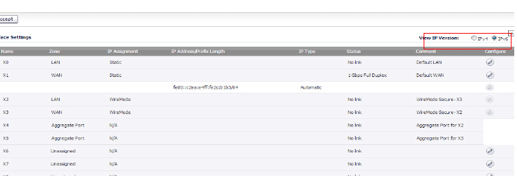
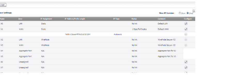
IPv6 interfaces are configured on the Network > Interfaces page by clicking the IPv6 option for the View IP Version radio button at the top right corner of the page.
By default, all IPv6 interfaces appear as routed with no IP address. Multiple IPv6 addresses can be added on the same interface. Auto IP assignment can only be configured on WAN interfaces.
Each interface can be configured to receive router advertisement or not. IPv6 can be enabled or disabled on each interface.
Note The zone assignment for an interface must be configured through the IPv4 interface page before switching to IPv6 mode.
The following sections describe IPv6 interface configuration:
• IPv6 Interface Configuration Constraints
• Configuring an Interface for IPv6 Static Mode
• Configuring an Interface for DHCPv6 Mode
• Configuring an Interface for Auto Mode
• Configuring an Interface for PPPoE
• Configuring a VLAN Sub-Interface
• Configuring an Interface for Wire Mode
IPv6 Interface Configuration Constraints
• The HA interface cannot be configured for IPv6.
• Only the parent interface of a SwitchPort group can be configured as an IPv6 interface, hence all children of a switch port group must be excluded from this list.
• Zone and Layer 2 Bridge groups are shared configurations between by IPv4 and IPv6 on an interface. Once they are configured on the IPv4 side, the IPv6 side of the interface will use the same configuration.
• Default Gateway and DNS Servers can only be configured for WAN zone interfaces.
• Wire mode is supported for IPv6, but you can not edit any settings. Instead, SonicOS uses the same configuration options set for IPv4.
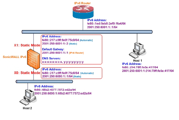
Configuring an Interface for IPv6 Static Mode
Static mode provides user a way to assign static IPv6 address as opposed to an auto-assigned address. Using static mode, the IPv6 interface can still listen for Router Advertisements and learn an autonomous address from the appropriate prefix option. Static Mode does not disturb the running of Stateless Address Autoconfiguration on IPv6 interface unless the user manually disables it.
The following diagram shows a sample topology with IPv6 configured in static mode.
Three types of IPv6 address are possible to assign under this mode:
• Automatic Address
• Autonomous Address
• Static Address
To configure an interface for a static IPv6 address, perform the following steps:
1. Navigate to the Network > Interfaces page.
2. Click on the IPv6 button at the top right corner of the page. IPv6 addresses for the appliance are displayed.
3. Click on the Configure icon for the interface you want to configure an IPv6 address for. The Edit Interface dialog boxInterface dialog box displays.
Note The zone assignment for interfaces must be configured on the IPv4 addressing page. To modify the zone assignment for an IPv6 interface, click the IPv4 button at the top right of the page, modify the zone for the interface, and then return to the IPv6 interface page.
In the IP Assignment pulldown menu, select Static.
5. Enter the IPv6 Address for the interface.
6. Enter the Prefix Length for the address.
7. If this is the primary WAN interface, enter the IPv6 address of the Default Gateway. If this is not the primary WAN interface, any Default Gateway entry will be ignored, so you can leave this as ::. (The double colon is the abbreviation for an empty address, or 0:0:0:0:0:0:0:0.)
8. If this is the primary WAN interface, enter up to three DNS Server IPv6 addresses. Again, if this is not the primary WAN interface, any DNS Server entries will be ignored.
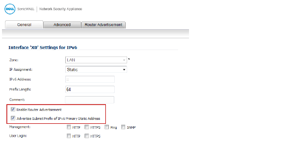
9. Select Enable Router Advertisement to make this an advertising interface that distributes network and prefix information.
10. Select Advertise Subnet Prefix of IPv6 Primary Static Address to add a default prefix into the interface advertising prefix list. This prefix is the subnet prefix of interface IPv6 primary static address. This option will help all hosts on the link stay in the same subnet.
Configuring Advanced IPv6 Interface Options and Multiple IPv6 Addresses
Perform the following steps to modify Advanced IPv6 interface options or to configure multiple static IPv6 addresses.
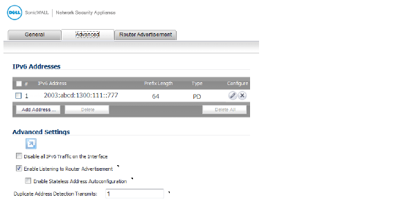
1. In the Edit Interface dialog box, click on the Advanced tab.
Click the Add Address button to configure multiple static IPv6 addresses for the interface.
Multiple IPv6 addresses can only be added for an interface that is configured for Static IPv6 address mode. Multiple IPv6 addresses cannot be configured for Auto or DHCPv6 modes.
3. Enter the IPv6 Address for the additional address for the interface.
4. Enter the Prefix Length for the address.
5. Select Advertise Subnet Prefix of IPv6 Primary Static Address to add a default prefix into the interface advertising prefix list. This prefix is the subnet prefix of interface IPv6 primary static address. This option will help all hosts on the link stay in the same subnet.
6. Click OK.
7. The following additional options can be configured on the Advanced tab under the Advanced Settings heading:
– Select Disable all IPv6 Traffic on the Interface to stop the interface from handling all IPv6 traffic. Disabling IPv6 traffic can improve firewall performance for non-IPv6 traffic. If the firewall is deployed in a pure IPv4 environment, Dell SonicWALL recommends enabling this option.
– Select Enable Listening to Router Advertisement to have the firewall receive router advertisement. If disabled, the interface filters all incoming Router Advertisement message, which can enhance security by eliminating the possibility of receiving malicious network parameters (e.g. prefix information or default gateway). This option is not visible for Auto mode. In Auto mode, it is always enabled.
– Select Enable Stateless Address Autoconfiguration to allow autonomous IPv6 addresses to be assigned to this interface. If unchecked, all assigned autonomous IPv6 address will be removed from this interface. This option is not visible for Auto mode. In Auto mode, it is always enabled.
– Enter a numeric value for Duplicate Address Detection Transmits to specify the number of consecutive Neighbor Solicitation messages sent while performing Duplicate Address Detection (DAD) before assigning a tentative address to interface. A value of 0 indicates that DAD is not performed on the interface.
– Similar with IPv4 gratuitous ARP, IPv6 node uses Neighbor Solicitation message to detect duplicate IPv6 address on the same link. DAD must be performed on any Unicast address (except Anycast address) before assigning a tentative to an IPv6 interface.
Configuring Router Advertisement Settings
Router Advertisement allows IPv6 routers to advertise DNS recursive server addresses to IPv6 hosts. Router Advertisement-based DNS configuration is a useful, optional alternative in networks where an IPv6 host's address is autoconfigured through IPv6 stateless address autoconfiguration, and where the delays in acquiring server addresses and communicating with the servers are critical. Router Advertisement allows the host to acquire the nearest server addresses on every link. Furthermore, it learns these addresses from the same RA message that provides configuration information for the link, thereby avoiding an additional protocol run. This can be beneficial in some mobile environments, such as with Mobile IPv6. Dell SonicWALL’s implementation of IPv6 is full conformable with RFC 4861 in Router and Prefix Discovery.
Note Router Advertisement can only be enabled when interface is under Static mode.
To configure Router Advertisement for an IPv6 interface, perform the following steps.
1. In the Edit Interface dialog box, click on the Router Advertisement tab.
Select the Enable Router Advertisement checkbox to have make this an advertising interface that will distribute network and prefix information.
3. Optionally, you can modify the following Router Advertisement settings:
– Router Adv Interval Range - The time interval allowed between sending unsolicited multicast Router Advertisements from the interface, in seconds.
– Link MTU - The recommended MTU for the interface link. A value of 0 means firewall will not advertise link MTU for the link.
– Reachable Time - The time that a node assumes a neighbor is reachable after having received a reachability confirmation. A value of 0 means this parameter is unspecified by this firewall.
– Retrans Time - The time between retransmitted Neighbor Solicitation messages. A value of 0 means this parameter is unspecified by this firewall.
– Current Hop Limit - The default value that should be placed in the Hop Count field of the IP header for outgoing IP packets. A value of 0 means this parameter is unspecified by this firewall.
– Router Lifetime - The lifetime when firewall is accepted as a default router. A value of 0 means that the router is not a default router.
4. Select the Managed checkbox to set the managed address configuration flag in the Router Advertisement message. If set, it indicates that IPv6 addresses are available via Dynamic Host Configuration Protocol.
5. Select the Other Configuration checkbox to set the Other configuration flag in Router Advertisement message. If set, it indicates that other configuration information is available via Dynamic Host Configuration Protocol.
Configuring Router Advertisement Prefix Settings
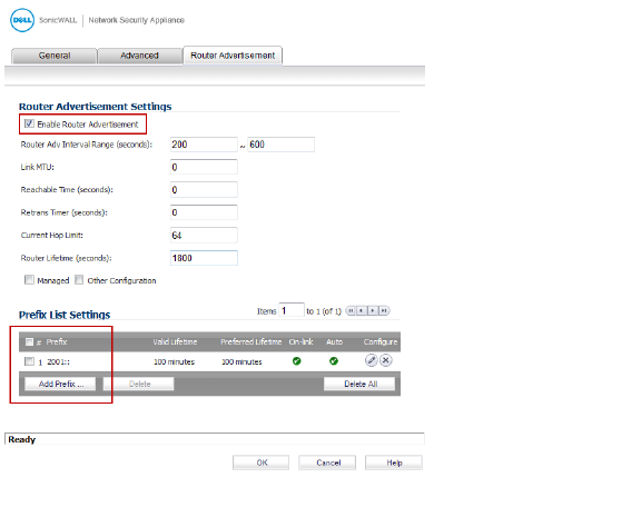
1. Click the Add Prefix button to configure an advertising prefix. Advertising prefixes are used for providing hosts with prefixes for on-link determination and Address Autoconfiguration.
Enter the Prefix that is to be advertised with the Router Advertisement message.
3. Enter the Valid Lifetime to set the length of time (in minutes) that the prefix is valid for the purpose of on-link determination. A value of “71582789” means the lifetime is infinite.
4. Enter the Preferred Lifetime to set the length of time that addresses generated from the prefix via stateless address autoconfiguration remain preferred. A value of “71582789” means the lifetime is infinite.
5. Optionally click the On-link checkbox to enable the on-link flag in Prefix Information option, which indicates that this prefix can be used for on-link determination.
6. Optionally click the Autonomous checkbox to enable the autonomous address-configuration flag in Prefix Information option, which indicates that this prefix can be used for stateless address configuration.
7. Click OK.
Configuring an Interface for DHCPv6 Mode
DHCPv6 (DHCP for IPv6) is a client/server protocol that provides stateful address configuration or stateless configuration setting for IPv6 hosts. DHCPv6 client is enabled to learn IPv6 address and network parameters when interface is configured to DHCPv6 mode.
DHCPv6 defines two different configuration modes:
• DHCPv6 stateful mode: DHCPv6 clients require IPv6 address together with other network parameters (e.g. DNS Server, Domain Name, etc.).
• DHCPv6 stateless mode: DHCPv6 client only obtains network parameters other than IPv6 address. Choosing which kind of those modes depends on Managed (M) Address Configuration and Other (O) Configuration flag in the advertised Router Advertisement message:
– M = 0, O = 0: No DHCPv6 infrastructure.
– M = 1, O = 1: IPv6 host use DHCPv6 for both IPv6 address and other network parameter settings.
– M = 0, O = 1: IPv6 host use DHCPv6 only for IPv6 address assignment.
– M = 1, O = 0: IPv6 host use DHCPv6 only for other network parameter settings, which known as DHCPv6 stateless.
The following diagram shows a sample DHCPv6 topology.
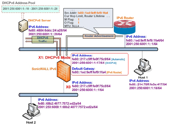
There are three types of IPv6 addresses that can be assign under DHCPv6:
• Automatic Address
• Autonomous Address
• IPv6 Address assigned through DHCPv6 client
To configure an interface for a DHCPv6 address, perform the following steps:
1. Navigate to the Network > Interfaces page.
2. Click on the IPv6 button at the top right corner of the page. IPv6 addresses for the appliance are displayed.
3. Click on the Configure icon for the interface you want to configure an IPv6 address for. The Edit Interface dialog box displays.
4. In the IP Assignment pulldown menu, select DHCPv6.
The following options can be configured for IPv6 interfaces configured for DHCPv6 mode:
– Use Rapid Commit Option - If enabled, DHCPv6 client use Rapid Commit Option to use the two message exchange for address assignment.
– Send hints for renewing previous IP on startup - If enabled, DHCPv6 client will try to renew the address assigned before when firewall startup.
6. Set the DHCPv6 Mode for the interface. As required by RFC, DHCPv6 client depends on Router Advertisement message to decide which mode (stateful or stateless) it should choose. This definition will limit user's choice if they want to determine DHCPv6 mode by itself. Dell SonicWALL’s implementation of DHCPv6 defines two different modes to balance the conformance and flexibility:
– Automatic - In this mode, IPv6 interface configures IPv6 addresses using stateless/stateful autoconfiguration in accord with the M and O settings in the most recently received router advertisement message.
– Manual - In Manual mode, DHCPv6 mode is manually configured regardless of any received Router Advertisement. The Only Request Stateless Information option will determine which DHCPv6 mode is used. If this option is unchecked, DHCPv6 client is under stateful mode; if it is checked, DHCPv6 client is under stateless mode and only obtains network parameters.
7. Optionally, select the Only Request Stateless Information checkbox to have DHCPv6 clients only requests network parameter setting from the DHCPv6 server. The IPv6 address is assigned through stateless auto-configuration.
8. Optionally, you can configure Management login or User Login.
9. Click OK to complete the configuration, or click the Advanced tab to configure Advanced options or click the Protocol tab to view DHCPv6 stateful and stateless configuration information.
Configuring Advanced Settings for an IPv6 Interface
The following options can be configured on the Advanced tab of the IPv6 Edit Interface dialog box:
• Select Disable all IPv6 Traffic on the Interface to stop the interface from handling all IPv6 traffic. Disabling IPv6 traffic can improve firewall performance for non-IPv6 traffic. If the firewall is deployed in a pure IPv4 environment, Dell SonicWALL recommends enabling this option.
• Select Enable Listening to Router Advertisement to have the firewall receive router advertisement. If disabled, the interface filters all incoming Router Advertisement message, which can enhance security by eliminating the possibility of receiving malicious network parameters (e.g. prefix information or default gateway). This option is not visible for Auto mode. In Auto mode, it is always enabled.
• Select Enable Stateless Address Autoconfiguration to allow autonomous IPv6 addresses to be assigned to this interface. If unchecked, all assigned autonomous IPv6 address will be removed from this interface. This option is not visible for Auto mode. In Auto mode, it is always enabled.
• Enter a numeric value for Duplicate Address Detection Transmits to specify the number of consecutive Neighbor Solicitation messages sent while performing Duplicate Address Detection (DAD) before assigning a tentative address to interface. A value of 0 indicates that DAD is not performed on the interface.
Similar with IPv4 gratuitous ARP, IPv6 node uses Neighbor Solicitation message to detect duplicate IPv6 address on the same link. DAD must be performed on any Unicast address (except Anycast address) before assigning a tentative to an IPv6 interface.
DHCPv6 Protocol Tab
When configuring an IPv6 interface in DHCpv6 mode, the Protocol tab displays additional DHCPv6 information.
The following information is displayed on the Protocol tab:
• DHCPv6 State: If the interface is configured for Stateless mode, the DHCPv6 State will be Stateless. If the interface is configured for Stateful mode, the DHCPv6 State will be either Enable or Disabled. When the interface is in Stateful, DHCPv6 mode, mousing over the icon to the left of the DHCPv6 State will display current Router Advertisement information for the interface.
• DHCPv6 Server: The IPv6 address of the DHCPv6 server.
• Stateful Addresses Acquired via DHCPv6: Displays information on any acquired stateful IPv6 addresses.
• DNS Servers: The IPv6 addresses of any DNS Servers.
Configuring an Interface for Auto Mode
Auto mode utilities IPv6’s Stateless Address Autoconfiguration to assign IPv6 address. This mode does not require any manual address configuration by the network administrator. The firewall listens to the network and receives prefix information from neighboring routers. The IPv6 Stateless Address Autoconfiguration feature performs all configuration details, such as IPv6 address assignment, address deleting for address conflicting or lifetime expiration, and default gateway selection based on the information collected from on-link router.
Note Auto mode can only be configured for the WAN zone. For security consideration, Auto mode is not available on LAN zone interface.
The following diagram shows a sample topology for IPv6 configured in Auto mode.
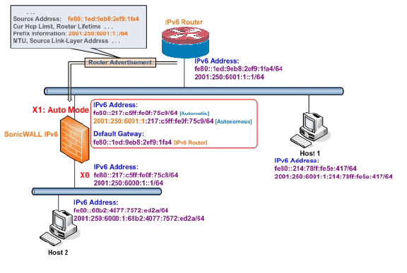
In this mode, 2 types of IPv6 address are possible to assign:
• Automatic Address - The interface default link-local address. It is never timed out and is not able to be edited or deleted.
• Autonomous Address - Assigned from Stateless Address Autoconfiguration. Users can manually delete the address if they do not want to wait for its valid lifetime expires.
To configure an IPv6 interface for Auto mode, perform the following steps:
1. Navigate to the Network > Interfaces page.
2. Click on the IPv6 button at the top right corner of the page to display IPv6 addresses.
3. Click on the Configure icon for the interface you want to configure an IPv6 address for. The Edit Interface dialog box displays.
In the IP Assignment pulldown menu, select Auto.
Optionally, you can select enter a numeric value for Duplicate Address Detection Transmits on the Advanced tab to specify the number of consecutive Neighbor Solicitation messages sent while performing Duplicate Address Detection (DAD) before assigning a tentative address to interface. A value of 0 indicates that DAD is not performed on the interface.
6. Click OK.
Configuring an Interface for PPPoE
Point-to-Point Protocol Over Ethernet (PPPoE) for IPv6 provides the ability to connect a network of hosts over a simple bridging access device to a remote Access Concentrator in the IPv6 network. Each host utilizes its own Point-to-Point Protocol stack and the user is presented with a familiar user interface. The access control, billing, and type of service can be done on a per-user basis, rather than a per-site. PPPoE for IPv4 and IPv6 use the same interface to avoid multiple PPPoE connections on the same interface, and PPPoE for IPv6 cannot be applied alone, it must be used with PPPoEv4 at the same time. This means you must configure the IPv4 assignment to PPPoE mode before configuring PPPoE for IPv6 on the interface. Once the PPPoE connection for IPv6 is established, it can also pass IPv4 traffic.and communicate beyond the local network.
To configure an interface for PPPoE with IPv6, perform the following steps:
1. Navigate to the Network > Interfaces page in the Management Interface.
2. Configure an interface in IPv4 to use PPPoE.
3. Change the View IP Version radio button to IPv6.
4. Click the Configure icon for the desired interface.
5. Configure the interface parameters in the General and Protocol tabs.
Point-to-Point Protocol NCP negotiation can only negotiate the Link Local addresses, which are used to communicate within the local network, so a global address should be obtained to communicate beyond the local network.
6. To obtain a global address, configure the PPPoE global address acquired section in the General tab.
There are three ways for obtaining a global address:
Auto
The default global address is set to Auto, which provides a link local address.
a. Select Auto from the PPPoE Address Assignment drop-down list.
b. Click the OK button.
Static
a. Select Static mode from the PPPoE Address Assignment drop-down list.
b. Click the OK button.
DHCPv6
a. Select DHCPv6 from the PPPoEv6 Address Assignment drop-down list.
b. In the Advanced tab, click the Enable Listening to Router Advertisement and Enable Stateless Address Auto-configuration checkboxes.
c. Click the OK button.
The PPPoE feature for IPv6 is now configured. To disable it, click the Disconnect button for the desired interface in the main Network > Interfaces page.
Configuring a VLAN Sub-Interface
The procedure for configuring a VLAN Sub-interface in IPv6 is identical to that in IPv4. Refer to Configuring VLAN Subinterfaces for details.
All VLAN Sub-interfaces must be configured in IPv4, before configuring them in IPv6.
Configuring an Interface for Wire Mode
The procedure for configuring a Wire Mode interface in IPv6 is identical to that in IPv4. Refer to Configuring an Interface for Wire Mode for details.
All Wire Mode interfaces must be configured in IPv4; you can not edit Wire Mode settings in IPv6. Any functionality enabled in IPv4 (for example, “Link State Propagation”) applies to IPv6.
Configuring IPv6 Tunnel Interfaces
This section describes how to tunnel IPv4 packets through IPv6 networks and IPv6 packets through IPv4 networks. For instance, in order to pass IPv6 packets through the IPv4 network, the IPv6 packet will be encapsulated into an IPv4 packet at the ingress side of a tunnel. When the encapsulated packet arrives at the egress of the tunnel, the IPv4 packet will be de-capsulated.
Tunnels can be either automatic or manually configured. A configured tunnel determines the endpoint addresses by configuration information on the encapsulating node. An automatic tunnel determines the IPv4 endpoints from the address of the embedded IPv6 datagram. IPv4 multicast tunneling determines the endpoints through Neighbor Discovery.
The following diagram depicts an IPv6 to IPv4 tunnel.
The following sections describe IPv6 Tunnel Interface configuration:
• Configuring the 6to4 Auto Tunnel
• Configuring 6to4 Relay for Non-2002 Prefix Access
• Configuring a Manual IPv6 Tunnel
• Configuring a GRE IPv6 Tunnel
• Configuring IPv6 Prefix Delegation on the Upstream Interface
• Configuring IPv6 Prefix Delegation on the Downstream Interface
• Configuring a 6rd Tunnel Interface
• Configuring an ISATAP Tunnel
Configuring the 6to4 Auto Tunnel
The 6to4 Auto Tunnel is an automatic tunnel: tunnel endpoints are extracted from the encapsulated IPv6 datagram. No manual configuration is necessary.
6to4 tunnels use a prefix of the form “2002:tunnel-IPv4-address::/48” to tunnel IPv6 traffic over IPv4. (for example, if the tunnel’s IPv4 endpoint has the address a01:203, the 6to4 tunnel prefix is “2002:a01:203::1.”) Routers advertise a prefix of the form “2002:[IPv4]:xxxx/64” to IPv6 clients. For complete information, see RFC 3056.
The following diagram shows a sample 6to4 auto tunnel topology.
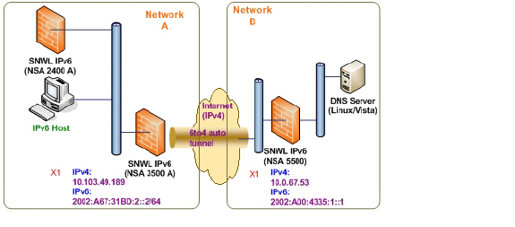
In the example, customers do not need to specify the tunnel endpoint, but only need to enable the 6to4 auto tunnel. All packets with a 2002 prefix will be routed to the tunnel, and the tunnel's IPv4 destination will be extract from the destination IPv6 address.
6to4 tunnels are easy to configure and use. Users must have a global IPv4 address and IPv6 address, which must also have a 2002 prefix. Therefore, in general, user can only access network resource with a 2002 prefix.
Note Only one 6to4 auto tunnel can be configured on the firewall.
To configure the 6to4 tunnel on the firewall, perform the following steps:
1. Navigate to the Network > Interfaces page.
2. Click the Add Interface button.
Select the Zone for the 6to4 tunnel interface. This is typically the WAN interface.
4. In the Tunnel Type pulldown menu, select 6to4 Auto Tunnel Interface.
5. By default, the interface Name is set to 6to4AutoTun.
6. Select the Enable IPv6 6to4 Tunnel checkbox.
7. Optionally, you can configure Management login or User Login over the 6to4 tunnel.
8. Click OK.
Configuring 6to4 Relay for Non-2002 Prefix Access
By default, 6to4 auto tunnel can only access the destination with a 2002 prefix. The 6to4 relay feature can be used to access non-2002 prefix destinations.
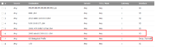
To enable 6to4 relay, go to Network > Routing. Then, click the Add button to create a Route Policy that can route all traffic destined for 2003 prefixes over the 6to4 aut tunnel interface, as shown in the following example:
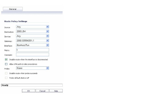
This static route can be added on the 6to4 auto tunnel interface to enable the relay feature, which makes it possible to access the IPv6 destination with non-2002: prefix through 6to4 tunnel. Note that, the gateway must be the IPv6 address with the 2002: prefix.
Configuring a Manual IPv6 Tunnel
To configure the 6to4 tunnel on the firewall, perform the following steps:
1. Navigate to the Network > Interfaces page.
2. Click the Add Interface button.
Select the Zone for the tunnel interface.
4. In the Tunnel Type pulldown menu, select IPv6 Manual Tunnel Interface.
5. Enter a Name for the tunnel interface.
6. Enter the Remote IPv4 address for the tunnel endpoint.
7. For the Remote IPv6 network select an IPv6 Address object, which can be a group, range, network, or Host.
8. Optionally, you can configure Management login or User Login over the 6to4 tunnel.
9. Click OK.
GRE can be used to tunnel IPv4 and IPv6 traffic over IPv4 or IPv6. GRE tunnels are static tunnels where both endpoints are specified manually. The following diagram shows a sample GRE IPv6 tunnel.
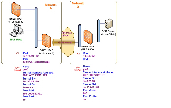
The configuration of a GRE tunnel is similar to a manual tunnel, except GRE Tunnel Interface is selected for the Tunnel Type.
IPv6 Prefix Delegation, also known as DHCPv6 Prefix Delegation (DHCPv6-PD), is an extension to DHCPv6. In DHCPv6, addresses are assigned by a DHCPv6 server to an IPv6 host. In DHCPv6-PD, complete IPv6 subnet addresses and other parameters are assigned by a DHCPv6-PD server to a DHCPv6-PD client.
When DHCPv6-PD is enabled, it is applied to all DHCPv6 interfaces attached to the WAN zone. DHCPv6-PD is an additional subnet-configuration mode that co-exists with DHCPv6.
The IPv6 address is a combination of the prefix provided by the DHCPv6-PD server and the suffix provided by the DHCPv6-PD client. The prefix length is 64 by default, but can be edited.
When the firewall starts, a default address object group called Prefixes from DHCPv6 Delegation is automatically created. Prefixes delegated from the upstream interface are members of this group.
IPv6 Prefix Delegation is configured on:
• An Upstream Interface
• One or More Downstream Interfaces
When the upstream interface learns the prefix delegation from the DHCPv6-PD server, SonicOS calculates and applies the IPv6 address prefixes to all the downstream interfaces, and the downstream interfaces advertise this information to all the hosts in their network segments.
This section contains the following configuration procedures:
• Configuring IPv6 Prefix Delegation on the Upstream Interface
• Configuring IPv6 Prefix Delegation on the Downstream Interface
Note Before you disable prefix delegation in your network, we recommend that you release the prefix delegation in the upstream interface first.
Configuring IPv6 Prefix Delegation on the Upstream Interface
To configure IPv6 Prefix Delegation on the upstream interface:
1. Go to the Network > Interfaces page.
2. At View IP Version, select IPv6.
3. Click the Edit icon in the Configure column for the Interface you want to configure as the upstream interface. The Edit Interface dialog box appears.
4. The Zone will always be WAN.
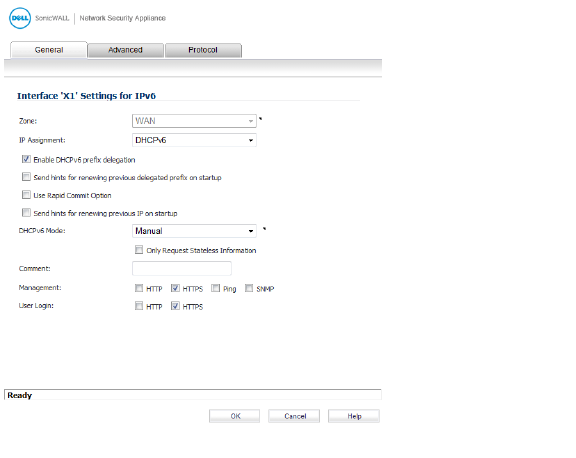
5. From the IP Assignment menu, select DHCPv6.
6. Select the Enable DHCPv6 prefix delegation option.
7. From the DHCPv6 Mode menu, select Manual.
8. To see the configured DHCPv6 information, click the Protocol tab.
In the DHCPv6 General Information panel, the DHCPv6 DUID is displayed.
In the Stateful Addresses Acquired via DHCPv6 panel, the stateful IAID is displayed.
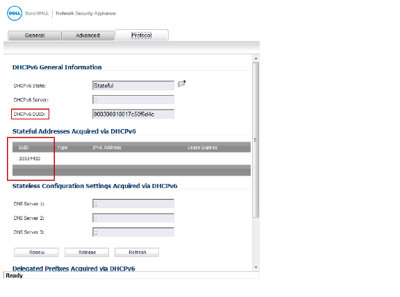
In the Delegated Prefixes Acquired via DHCPv6 panel, the delegated IAID is displayed.
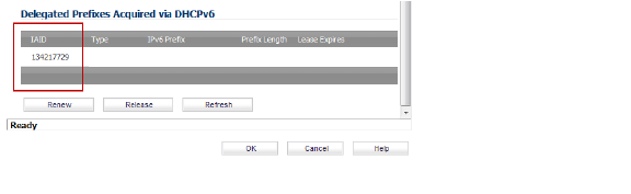
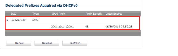
9. Click the Renew button.
The information for the other columns is displayed.
Configuring IPv6 Prefix Delegation on the Downstream Interface
To configure IPv6 Prefix Delegation on the downstream interface:
1. Go to the Network > Interfaces page.
2. Select the IPv6 option.
3. Click the Edit icon in the Configure column for the Interface you want to configure as the downstream interface. The Edit Interface dialog appears.
4. Select the Enable Router Advertisement option.
5. Click the Advanced tab. The Edit Interface dialog appears.
If the upstream prefix is obtained, it is displayed in the IPv6 Addresses panel.
6. If the upstream prefix cannot be obtained, an alternate address is displayed in the IPv6 Addresses panel.
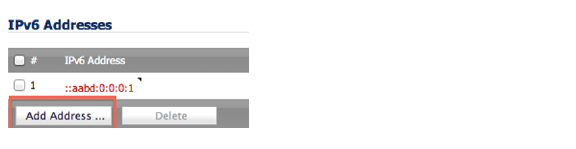
7. Click the Add Address button to display the Add IPv6 Address dialog box.
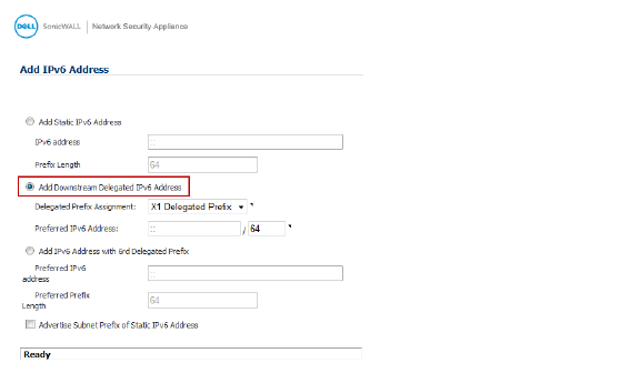
8. Select the Add Downstream Delegated IPv6 Address option.
9. (Optional) Select the Advertise Subnet Prefix of Static IPv6 Address option.
10. Click the Router Advertisement tab.
11. Select the Enable Router Advertisement option.
If you selected Advertise Subnet Prefix of Static IPv6 Address option under the General tab, the prefix will be listed in the Prefix List Settings panel.
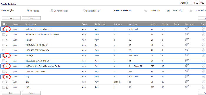
12. To see your new IPv6 PD interfaces, go to the Network > Routing page.
13. Select the IPv6 option.
The two new IPv6 interfaces with prefix delegation (upstream and downstream) are displayed.
IPv6 Rapid Deployment (6rd) enables IPv6 to be deployed across an IPv4 network quickly and easily. 6rd utilizes a Service Provider’s existing IPv6 address prefixes, ensuring that the 6rd operational domain is limited to the Service Provider’s network and is under the Service Provider’s direct control.
A 6rd tunnel interface is a virtual interface that transports 6rd encapsulated IPv6 packets in an IPv4 network.
Note A 6rd tunnel interface must be bound to a physical or a virtual interface.
When 6rd is deployed, the IPv6 service is equivalent to native IPv6. 6rd mapping of IPv6 addresses to IPv4 addresses provides automatic determination of IPv4 tunnel endpoints from IPv6 prefixes, allowing stateless operation of 6rd.
A 6rd domain consists of several 6rd customer edge (CE) routers and one or more 6rd border relay (BR) routers. IPv6 packets encapsulated by 6rd follow the IPv4 routing topology within the service provider network.
A typical 6rd implementation using customer edge routers and border relay routers requires only one 6rd tunnel interface. A border relay router servicing multiple 6rd domains may have more than one 6rd tunnel interface. However, each 6rd domain can have only one 6rd tunnel interface.
IPv6 packets traverse the border relays when they enter or exit a Service Provider’s 6rd domain. Since 6rd is stateless, packets can be sent to the border relays using the Anycast method, where packets from a single source are routed to the nearest node in a group of potential receivers, or to several nodes, all identified by the same destination address.
Service Providers may deploy 6rd in a single domain or in multiple domains. A 6rd domain can have only one 6rd prefix. Different 6rd domains must use different 6rd prefixes.
On the Network > Routing page, in the Route Policies panel, there are four default route policies for 6rd tunnel interfaces.
There are two configuration modes:
• Manual
• DHCP
The following four 6rd parameters can be set manually, or they can be set automatically by the DHCPv4 server if you select DHCP as the configuration mode.
• IPv4 Mask Length
• 6rd Prefix
• 6rd Prefix Length
• 6rd BR IPv4 Address
In DHCP mode, the 6rd parameters are received from the bound interface. In Manual mode, the 6rd parameters must be configured manually.
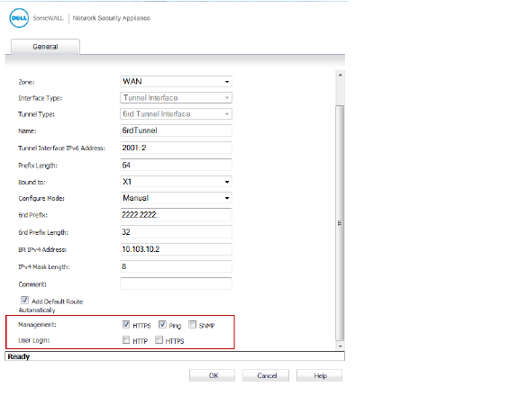
Configuring a 6rd Tunnel Interface
A 6rd tunnel interface is configured in the same way as other IPv6 tunnel interfaces. A bound interface is required to configure a 6rd tunnel interface.
To configure a 6rd tunnel interface:
1. Go to the Network > Interfaces page.
2. At View IP Version, select IPv6.
3. At the bottom of the Interface Settings panel, click the Add Interface button.
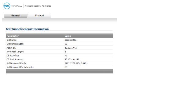
Note The Protocol tab is shown only when you select DHCP as the Configure Mode.
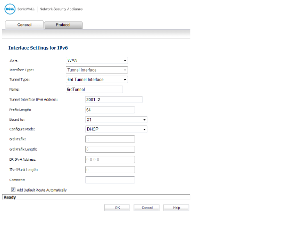
4. From the Zone menu, select WAN.
5. The Interface Type menu is disabled. It already has Tunnel Interface selected as it was selected from the Add Interface menu in Step 3.
6. From the Tunnel Type menu, select 6rd Tunnel Interface.
7. In the name box, enter a name for your tunnel interface, or example, 6rd Tunnel.
8. In the Tunnel Interface IPv6 Address box, enter the IPv6 address of the tunnel interface.
For example, 2001::2.
9. In the Prefix Length box, enter the length for the IPv6 prefix. For example, 64.
10. From the Bound to menu, select the interface that you want, such as X1.
11. From the Configure Mode menu, select the mode you want: Manual or DHCP.
Note If you select Manual as the Configure Mode, do steps 12 through 15.
If you select DHCP as the Configure Mode, skip steps 12 through 15.
12. In the 6rd Prefix box, enter the 6rd prefix, such as 2222:2222::
(Manual mode only).
13. In the 6rd Prefix Length box, enter the length for the 6rd prefix, such as 32
(Manual mode only).
14. In the IPv4 Mask Length box, enter the length of the IPv4 subnet mask
(Manual mode only).
15. In the BR IPv4 Address box, enter the IPv4 address of the 6rd border relay
(Manual mode only).
16. (Optional) In the Comment box, enter a comment to describe the tunnel interface.
17. Select the Add Default Route Automatically option.
18. Select the Management options that you want, or select the User Login options that you want.
If you selected Manual as the Configure Mode, your 6rd Tunnel Interface settings are shown under the General tab.
If you selected DHCP as the Configure Mode, your 6rd Tunnel Interface settings are shown under the Protocol tab.
ISATAP (Intra-Site Automatic Tunnel Addressing Protocol) can be used to provide IPv6 connectivity through an IPv4-only infrastructure. ISATAP is a simple tunneling mechanism that connects dual-stack (IPv6/IPv4) node to other dual-stack nodes or IPv6 nodes over IPv4 networks. The IPv4 network is viewed by ISATAP as a link layer for IPv6.
ISATAP can be used in several scenarios to provide unicast connectivity between ISATAP hosts, and ISATAP host and hosts on IPv6 networks.
Figure 1 shows the delivery of ISATAP traffic between ISATAP hosts on the same logical ISATAP subnet:
Figure 1
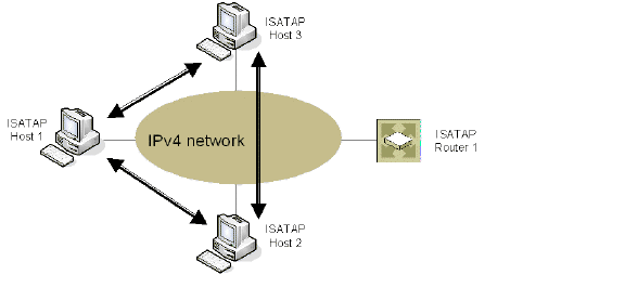
Figure 2 shows the delivery of ISATAP traffic between hosts on different ISATAP subnets:
Figure 2
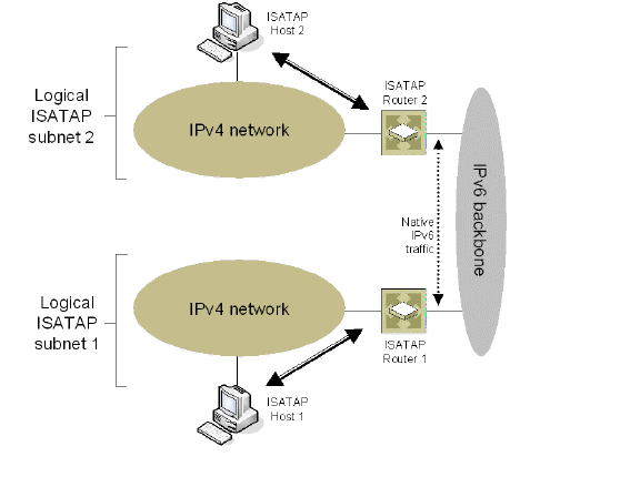
Figure 3 shows the delivery of packets between ISATAP hosts and hosts on an IPv6-capable network.
Figure 3
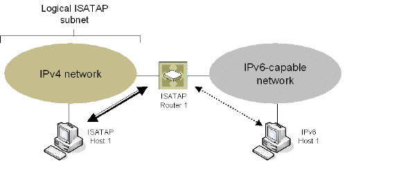
In the scenario presented in Figure 1, the ISATAP hosts can communicate directly to each other without going through the ISATAP router or IPv6 network. This allows an IPv6-capable application to leverage connectivity of an existing IPv4 infrastructure.
The other two scenarios require the ISATAP router to have an IPv6 interface connected to the IPv6 network which supports forwarding between the ISATAP interface-facing IPv4 network and the IPv6 interface.
ISATAP needs to be implemented and run in both the host and router. Dual-stack node support is enabled by default on the Windows XP and Windows 7 platforms.
ISATAP support in UTM allows the Dell SonicWALL to function as an ISATAP router on LAN- facing interfaces and forward IPv6 packets between the ISATAP tunneling interface and IPv6 interface connected to the IPv6 network.
To configure an ISATAP tunnel, perform the following tasks:
1. In the Network > Interfaces page, at View IP Version, select IPv6.
2. Click the Add Interface button.
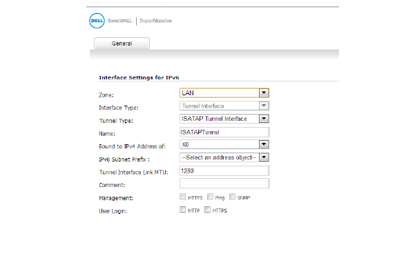
3. In the General tab, Select the Zone for the tunnel interface.
4. In the Tunnel Type drop-down list, select ISATAP Tunnel Interface.
5. Enter a Name for the tunnel interface.
6. Bound to IPv4 Address of - Select an interface from the drop-down list. The ISATAP tunnel uses the IPv4 address of the bound interface as the IPv4 end address of 6over4 tunnel.
7. IPv6 Subnet Prefix - Select an address object from the drop-down list (or select Create a new address object). The IPv6 subnet prefix is a 64 bit prefix, and is used by ISATAP hosts for ISATAP address auto configuration.
8. Tunnel Interface Link MTU - The recommended MTU for the interface link. A value of 0 means firewall will not advertise link MTU for the link.
9. Enter any optional comment text in the Comment field. This text is displayed in the Comment column of the Interface table.
10. If you want to enable remote management of the firewall from this interface, select the supported management protocol(s): HTTPS, Ping, or SNMP.
11. If you want to allow selected users with limited management rights to log in to the security appliance, select HTTP and/or HTTPS in User Login.
Additionally, you can specify how SonicOS resolves ISATAP host queries:
1. Navigate to the Firewall Settings > Advanced page.
2. Locate the IPv6 Advanced Configurations section.
– Enable NetBIOS name query response for ISATAP – Select this to if you want the security appliance to answer a NetBIOS query in order to help ISATAP hosts resolve the name into an IPv4 address.
– Resolved name ISATAP is valid for (seconds) – Enter a time period (in seconds).
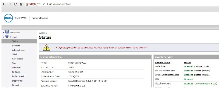
Accessing the Dell SonicWALL User Interface Using IPv6
After IPv6 addressing has been configured on the firewall, the Dell SonicWALL user interface can be accessed by entering the IPv6 of the firewall in your browser’s URL field.
• IPv6 DNS
DNS for IPv6 is configured using the same method as for IPv4. Click the IPv6 option in the View IP Version radio button at the top left of the Network > DNS page.
IPv6 address objects or address groups can be added in the same manner as IPv4 address objects. On the Network > Address Objects page, the View IP Version radio button has three options: IPv4 only, IPv6 only, or IPv4 and IPv6.
Address Objects of type Host, Range and Network are supported. Dynamic address objects for MAC and FQDN are not currently supported for IPv6 hosts.
IPv4 interfaces define a pair of a default Address Object (DAO) and an Address Object Group for each interface. The basic rule for IPv4 DAO is each IPv4 address corresponds to 2 address objects: Interface IP and Interface Subnet. There are also couples of AO groups for Zone Interface IP, Zone Subnets, All Interface IP, All Interface Management IP, etc.
IPv6 interface prepares the same DAO set for each interface. Because multiple IPv6 can be assigned to one interface, all of those address can be added, edited, and deleted dynamically. Therefore, IPv6 DAOs need to be created and deleted dynamically.
To address this, DAOs are not generated dynamically for IPv6 interfaces. Only limited interface DAO are created, which results in limitation support for other module which needs to refer interface DAO.
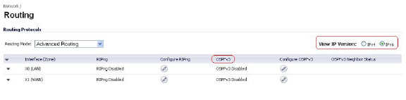
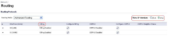
Policy Based Routing is fully supported for IPv6 by selecting IPv6 address objects and gateways for route policies on the Network > Routing page. On the Network > Routing page, the View IP Version radio button has three options: IPv4 only, IPv6 only, or IPv4 and IPv6. The OSPF feature displays two radio buttons to switch between version 2 and version 3.
Routing Information Protocol next generation (RIPng) is an information routing protocol for IPv6, which allows routers to exchange information for computing routes through an IPv6-based network.
A radio button is added to switch between RIP and RIPng:
NAT policies can be configured for IPv6 by selecting IPv6 address objects on the Network > NAT Policies page. On the Network > NAT Policies page, the View IP Version radio button has three options: IPv4 only, IPv6 only, or IPv4 and IPv6.
When configuring IPv6 NAT policies, the source and destination objects can only be IPv6 address objects.
Note IPv6 probing for NAT policies is not currently supported.
The Neighbor Discovery Protocol (NDP) is a new messaging protocol that was created as part of IPv6 to perform a number of the tasks that ICMP and ARP accomplish in IPv4. Just like ARP, Neighbor Discovery builds a cache of dynamic entries, and the administrator can configure static Neighbor Discovery entries. The following table shows the IPv6 neighbor messages and functions that are analogous to the traditional IPv4 neighbor messages.
|
The Static NDP feature allows for static mappings to be created between a Layer 3 IPv6 address and a Layer 2 MAC address.
To configure a Static NDP entry, perform the following steps:
Navigate to the Network > Neighbor Discovery page and then click the Add button.
In the IP Address field, enter the IPv6 address for the remote device.
3. In the Interface pulldown menu, select the interface on the firewall that will be used for the entry.
4. In the MAC Address field, enter the MAC address of the remote device.
5. Click OK. The static NDP entry is added.
The NDP Cache table displays all current IPv6 neighbors. The follow types of neighbors are displayed:
– REACHABLE - The neighbor is known to have been reachable within 30 seconds.
– STALE - The neighbor is no longer known to be reachable, and traffic has been sent to the neighbor within 1200 seconds.
– STATIC - The neighbor was manually configured as a static neighbor.
The Network > Multicast Routing page is used to configure multicast settings for IPv6, which are divided into the two following sections:
• Multicast Listener Discovery
Maintaining interoperability between IPv6 and IPv4 networks is one of the main challenges of implementing IPv6 in a network. While packet-based multicast translation can be used, Dell SonicWALL supports a multicast proxy solution that can be deployed at the border between IPv6 and IPv4 networks. The Dell SonicWALL receives multicast data from the IPv4 network, caches it, and then multicasts the data to the IPv6 network. (And vice versa for sending multicast data from the IPv6 to the IPv4 network.) This is accomplished without the need for packet-based translation.
To configure Multicast Proxy between IPv6 and IPv4 networks, perform the following steps:
1. Navigate to the Network > Multicast Routing page.
2. Select the Enable Multicast Proxy checkbox.
3. In the Upstream Interface pulldown menu, select the interface that is connected to the IPv6 network.
4. In the Downstream Interface pulldown menu, select the interface that is connected to the IPv4 network.
5. Click the Accept button. Multicast data will now be proxied \.
The Multicast Listener Discovery (MLD) protocol is used by IPv6 routers to discover multicast listeners that are directly connected to the firewall. MLD performs a similar function for IPv6 that IGMP is used for in IPv4. There are two versions of MLD. MLDv1 is similar to IGMPv2, and MLDv2 similar to IGMPv3.
|
MLD functionality does not require any explicit configuration. There are several variables that can be fine-tuned to modify the MLD behavior:
• Multicast Router Query Interval: Specifies the length in seconds between MLD queries. The default value is 125 seconds.
• Multicast Last Listener Query Interval: The maximum time that the router waits before deleting a nonresponsive port from the multicast group. Reducing this value will reduce the time required for the firewall to detect the departure of the last listener for a multicast address or source. The default value is 1000 milliseconds (1 second).
• Multicast Router Query Response Interval: The Maximum Response Delay that is inserted into the periodic MLD queries. By varying the Multicast Router Query Response Interval, an administrator may tune the burstiness of MLD messages on the link; larger values make the traffic less bursty, as host responses are spread out over a larger interval. The Multicast Router Query Response Interval must be less than the Query Interval.The default value is 10000 milliseconds (10 seconds).
• Multicast Router Robustness Variable: Specifies the number of queries that will be sent with no response before the target is deleted. This variable allows tuning the protocol according to the expected packet loss on a link. For lossy links (wireless connections, for example), the value of the Robustness Variable may be increased. The default value is 2. The Robustness Variable should not be configured for less than 2.
DHCPv6 server can be configured similar to IPv4 after selecting the IPv6 option in the View IP Version radio button at the top left of the Network > DNS page.
IPv6 Access Rules Configuration
IPv6 firewall access rules can be configured in the same manner as IPv4 access rules by choosing IPv6 address objects instead of IPv4 address objects. On the Firewall > Access Rules page, the View IP Version radio button has three options: IPv4 only, IPv6 only, or IPv4 and IPv6.
When adding an IPv6 access rule, the source and destination can only be IPv6 address objects.
IPv6 Advanced Firewall Settings
You can configure advanced firewall settings for IPv6, including packet limitations and traffic restrictions on the Firewall Settings > Advanced. See IPv6 Advanced Configuration for more information.
IPSec VPNs can be configured for IPv6 in a similar manner to IPv4 VPNs after selecting the IPv6 option in the View IP Version radio button at the top left of the VPN > Settings page.
There are certain VPN features that are currently not supported for IPv6, including:
• IKEv2 is supported, while IKE is currently not supported
• GroupVPN is not supported
• DHCP Over VPN is not supported.
When configuring an IPv6 VPN policy, on the General tab the gateways must be configured using IPv6 addresses. FQDN is not supported. When configuring IKE authentication, IPV6 addresses can be used for the local and peer IKE IDs.
DHCP Over VPN and L2TP Server are not supported for IPv6.
On the Network tab of the VPN policy, IPV6 address objects (or address groups that contain only IPv6 address objects) must be selected for the Local Network and Remote Network.
DHCP Over VPN is not supported, thus the DHCP options for protected network are not available.
The Any address option for Local Networks and the Tunnel All option for Remote Networks are removed. Select an all zero IPv6 Network address object could be selected for the same functionality and behavior.
On the Proposals tab, the configuration is identical for IPv6 and IPv4, except for the fact that IPv6 only support IKEv2 mode.
On the Advanced tab, only Enable Keep Alive and the IKEv2 Settings can be configured for IPv6 VPN policies.
Note Because an interface may have multiple IPv6 address, sometimes the local address of the tunnel may vary periodically. If the user needs a consistent IP address, configure the VPN policy to be bound to an interface instead of Zone, and specify the address manually. The address must be one of IPv6 addresses for that interface.
SSL VPN Configuration for IPv6
SonicOS supports NetExtender connections for users with IPv6 addresses. On the SSLVPN > Client Settings page, first configure the traditional IPv6 IP address pool, and then configure an IPv6 IP Pool. Clients will be assigned two internal addresses: one IPv4 and one IPv6.
IPv6 DNS/Wins Server are not supported
On the SSLVPN > Client Routes page, user can select a client routes from the drop-down list of all address objects including all the pre-defined IPv6 address objects.
Note IPv6 FQDN is supported.
IPv6 Visualization for the App Flow Monitor and Real-Time Monitor is an extension of the IPv4 Visualization, providing real-time monitoring of interface/application rates and visibility of sessions in the management interface.
With the new visualization dashboard monitoring improvements for IPv6, administrators are able to respond more quickly to network security vulnerabilities and network bandwidth issues. Administrators can see what websites their employees are accessing, what applications and services are being used in their networks and to what extent, in order to police content transmitted in and out of their organizations.
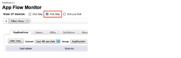
The App Flow Monitor page has two new options for the View IP Version selection. These allow you to monitor IPv6 only or IPv4 and IPv6 traffic.
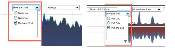
The Real-Time Monitor page has the same two new options under the Interface drop-down menu in the Applications and Bandwidth panels.
IPv6 Visualization Feature Limitations
Visualization for IPv6 has the following feature limitations:
• The IPv6 URL Rating is not supported, because CFS does not support all aspects of IPv6.
• IPv6 Country information is not supported.
• IPv6 External Reporting is not supported.
Configuring IPv6 Visualization
App Flow Monitor and Real-Time Monitor Visualization is configured the same in IPv6 and IPv4, select the View IP Version radio buttons to change the view/configuration. Refer to Visualization Dashboard for more information on general configuration on Visualization.
IPv6 High Availability Monitoring
IPv6 High Availability (HA) Monitoring is implemented as an extension of HA Monitoring in IPv4. After configuring HA Monitoring for IPv6, both the primary and backup appliances can be managed from the IPv6 monitoring address, and IPv6 Probing is capable of detecting the network status of HA pairs.
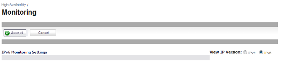
IPv6 and IPv4 radio buttons display in the High Availability > Monitoring page, toggle between the two views for easy configuration of both IP versions:
This section contains the following subsections:
• IPv6 High Availability Monitoring Feature Limitations
• IPv6 High Availability Probing
• Configuring IPv6 High Availability Monitoring
IPv6 High Availability Monitoring Feature Limitations
The IPv6 HA Monitoring feature limitations are as follows:
• Physical/Link Monitoring property cannot be changed in the IPv6 HA Monitoring configuration page. Set the property in the IPv4 HA Monitoring configuration page.
• Override Virtual MAC property cannot be changed in IPv6 HA Monitoring configuration page. Set the property in the IPv4 HA Monitoring configuration page.
• HA Probing cannot be enabled on both IPv4 and IP{v6 at the same time. That is, if IPv4 probing is enabled, then IPv6 probing must be disabled, and vice versa.
IPv6 High Availability Probing
An ICMPv6 packet is periodically sent out from the primary and backup appliances to probe the IPv6 address, and the response from the probed IPv6 address is monitored. If the active appliance cannot reach the probed IPv6 address, but the idle appliance can, the backup appliance has a better network status and failover initiates.
In IPv6 HA Probing the IPv6 addresses, ICMPv6 echo requests, and ICMPv6 echo replies are used. The logic used to judge network status of the primary and backup appliance is the same for IPv4 and IPv6.
Configuring IPv6 High Availability Monitoring
The IPv6 HA Monitoring configuration page is inherited from IPv4, so the configuration procedures are almost identical. Just select the IPv6 radio button and refer to IPv6 for configuration details.
Consider the following when configuring IPv6 HA Monitoring:
• The Physical/Link Monitoring and Virtual MAC checkboxes are greyed out because they are layer two properties. That is, the properties are used by both IPv4 and IPv6, so user has to configure them in the IPv4 monitoring page.
• The primary/backup IPv6 address must be in the same subnet of the interface, and it can not be same as the global IP and Link-Local-IP of the primary/backup appliance.
• If the primary/backup monitoring IP is set to (not ::), then they cannot be the same.
• If the Management checkbox is enabled, then primary/backup monitoring IP cannot be unspecified (i.e. ::).
• If the probe checkbox is enabled, then the probe IP cannot be unspecified.
IPv6 Diagnostics and Monitoring
SonicOS provides a full compliment of diagnostic tools for IPv6, including the following:
• IPv6 DNS Lookup and Reverse Name Lookup
Packet Capture fully supports IPv6.
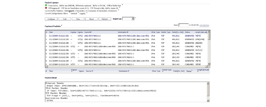
In addition, IPv6 keywords can be used to filter the packet capture.
The ping tool includes a new Prefer IPv6 networking option.
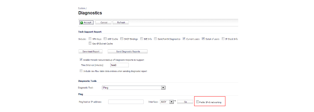
When pinging a domain name, it uses the first IP address that is returned and shows the actual pinging address. If both an IPv4 and IPv6 address are returned, by default, the firewall pings the IPv4 address.
If Prefer IPv6 networking is enabled, the firewall will ping the IPv6 address.
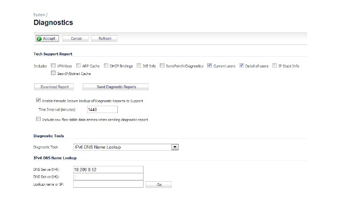
IPv6 DNS Lookup and Reverse Name Lookup
When performing IPv6 DNS Lookup or IPv6 Reverse Name Lookup, you must enter the DNS server address. Either an IPv6 or IPv4 address can be used.