Policies_Network_Interfaces_Snwls
You can configure the LAN interface in five different modes:
• Static IP—Uses a static IP address and acts as a gateway for devices on the LAN.
• Transparent Mode—Allows you to assign a single IP address to two physical interfaces, where each interface accesses an exclusive range of IP addresses in the shared subnet. Behaves as a proxy at Layer 3, intercepting ARPs and changing source MAC addresses of packets traversing the interface pair.
• Layer 2 Bridged Mode—Similar to Transparent Mode, but dynamically learns IP addresses on both interfaces so that you do not need to subdivide the subnet that is being bridged. Provides deep-packet inspection and application of policies before forwarding packets. Places the bridged interfaces into promiscuous mode and passes traffic between them with source and destination MAC addresses intact.
• Wired Mode—Adding to the broad collection of traditional modes of SonicOS interface operation, including all LAN modes (Static, NAT, Transparent Mode, L2 Bridge Mode, Portshield Switch Mode), and all WAN modes (Static, DHCP, PPPoE, PPTP, and L2TP), SonicOS 5.8 introduces Wire-Mode, which provides four new methods non-disruptive, incremental insertion into networks.
• Tap Mode—Provides the same visibility as Inspect Mode, but differs from the latter in that it ingests a mirrored packet stream via a single switch port on the SonicWALL security appliance, eliminating the need for physically intermediated insertion. Tap Mode is designed for use in environments employing network taps, smart taps, port mirrors, or SPAN ports to deliver packets to external devices for inspection or collection. Like all other forms of Wire Mode, Tap Mode can operate on multiple concurrent port instances, supporting discrete streams from multiple taps.
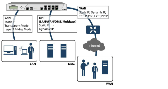
Figure 10:1 shows the basic interfaces for a SonicWALL appliance. The WAN interface can use a static or dynamic IP address and can connect to the Internet via Transmission Control Protocol (TCP), Point-to-Point Protocol over Ethernet (PPPoE), Level 2 Tunneling Protocol (L2TP), or Point-to-Point Tunneling Protocol (PPTP).
A SonicWALL appliance might have one, many, or no optional interfaces. Optional interfaces can be configured for LAN, WAN, DMZ, WLAN, or Multicast connections, or they can be disabled.
On the SonicWALL NSA Series and SonicWALL PRO 2040/3060/4060/4100/5060 security appliances, virtual Interfaces are sub-interfaces assigned to a physical interface. Virtual interfaces allow you to have more than one interface on one physical connection. Virtual interfaces provide many of the same features as physical interfaces, including Zone assignment, DHCP Server, and NAT and Access Rule controls. Selecting Layer 2 Bridged mode is not possible for a VLAN interface.
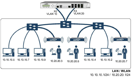
VLAN support on SonicOS Enhanced is achieved by means of sub-interfaces, which are logical interfaces nested beneath a physical interface. Every unique VLAN ID requires its own sub-interface. For reasons of security and control, SonicOS does not participate in any VLAN trunking protocols, but instead requires that each VLAN that is to be supported be configured and assigned appropriate security characteristics.
Figure 10:2 VLAN Interfaces
SonicOS Enhanced 4.0 and higher can apply bandwidth management to both egress (outbound) and ingress (inbound) traffic on the WAN interface. Outbound bandwidth management is done using Class Based Queuing. Inbound Bandwidth Management is done by implementing ACK delay algorithm that uses TCP’s intrinsic behavior to control the traffic.
Class Based Queuing (CBQ) provides guaranteed and maximum bandwidth Quality of Service (QoS) for the SonicWALL security appliance. Every packet destined to the WAN interface is queued in the corresponding priority queue. The scheduler then dequeues the packets and transmits it on the link depending on the guaranteed bandwidth for the flow and the available link bandwidth.
Configuring Network Settings in SonicOS Enhanced
The following sections describe how to configure network settings in SonicOS Enhanced:
• Configuring Interface Settings
• WAN Failover and Load Balancing
• Configuring Web Proxy Forwarding Settings
• Configuring Routing in SonicOS Enhanced
• Configuring RIP in SonicOS Enhanced
• Configuring PortShield Groups
• Configuring MAC-IP Anti-Spoof
Configuring Interface Settings
Interface settings define the networks associated with the LAN, WAN, optional (OPT), and WWAN interfaces. This includes protocols, gateways, DNS servers, Virtual LANs, and management settings.
Note Group level interface edits are only available for SonicWALL firewall appliances.
For a WWAN interface, GMS navigates directly to the Network > WWAN > Settings screen. For configuration information, refer to the Configuring WWAN Settings.
To configure the network interface general settings for one or more SonicWALL appliance, select the desired configuration from the following:
• Layer 2 Bridge Bypass Relay Control
• Configuring Link Aggregation (SonicOS 5.9 or higher)
• Port Redundancy (SonicOS 5.9 or higher)
• Configuring VLAN Sub-Interfaces
Static means that you assign a fixed IP address to the interface.
1. Click on the Configure icon ![]() in the Configure column for the Interface you want to configure. The Edit Interface window is displayed.
in the Configure column for the Interface you want to configure. The Edit Interface window is displayed.
– If you want to create a new zone, select Create new zone. The Add Zone window is displayed. See the Network > Zones page for instructions on adding a zone.
2. Select a zone to assign to the interface. You can select LAN, WAN, DMZ, WLAN, or a custom zone.
3. Select Static from the IP Assignment menu.
4. Enter the IP address and subnet mask of the zone in the IP Address and Subnet Mask fields.
Note You cannot enter an IP address that is in the same subnet as another zone.
5. Enter an IP address for a Default Gateway (optional). This feature is not supported for WLAN and VPN zones.
6. Enter any optional comment text in the Comment field. This text is displayed in the Comment column of the Interface table.
7. If you want to enable remote management of the SonicWALL appliance from this interface, select the supported management protocol(s): HTTP, HTTPS, SSH, Ping, SNMP, and/or SSH.
8. If you want to allow selected users with limited management rights to log in to the security appliance, select HTTP and/or HTTPS in User Login.
9. Click OK.
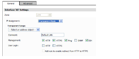
The following options are available when configuring an interface in Transparent Mode:
For LAN, DMZ, or Multicast interfaces, configure the following settings:
• For IP Assignment, select Static, Transparent Mode, or Layer 2 Bridged Mode. The display changes according to your selection. Configure the resulting field as follows:
– Static—For static IP addresses, enter the IP Address for the interface and Subnet Mask for the network.
– Transparent Mode—For transparent mode, select an address object that contains the range of IP addresses you want to have access through this interface in the Transparent Range menu.
– PortShield Switch Mode—For SonicWALL TZ 210, TZ 210W and NSA 240 appliances, you can configure interfaces for PortShield switch mode, which manually groups ports together to share a common network subnet as well as common zone settings. For more information, refer to the Configuring PortShield Groups.
Note When configuring a zone for Layer 2 Bridge Mode, the only access rule automatically added is an allow rule between the bridge pair. Other necessary access rules must be added manually.
The following options are available when configuring an interface in Layer 2 Bridge Mode:
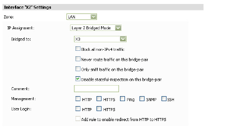
– Layer 2 Bridged Mode—On appliances running SonicOS Enhanced 3.5 and 4.0 or higher, you can select Layer 2 Bridged Mode for physical interfaces in either the LAN or the DMZ zone. On appliances running SonicOS Enhanced 5.5 or higher, you can select Layer 2 Bridge Mode for the WLAN zone.
: •: In the Bridged-to field, select a WAN, LAN, or DMZ interface with a static IP address.
: •: Select the Block all non-IPv4 traffic checkbox to allow only IPv4 traffic on this bridge-pair.
: •: Select the Never route traffic on this bridge-pair checkbox to prevent traffic from being routed to another interface.
: •: Select the Only sniff traffic on this bridge-pair checkbox to allow the bridged interface to be connected to a mirrored port on a switch in a one-arm mode to perform intrusion detection by examining traffic going through the switch.
: •: Select the Disable stateful-inspection on this bridge-pair to enable asymmetric routing on this interface.
Layer 2 Bridge Bypass Relay Control
The Engage physical bypass on malfunction option enables Layer 2 Bridge Bypass Relay Control, also known as “Fail to Wire.” The bypass relay option provides the user the choice of avoiding disruption of network traffic by bypassing the firewall in the event of a malfunction. The bypass relay will be closed for any unexpected anomaly (power failure, watchdog exception, fallback to safe-mode).
Note The Engage physical bypass on malfunction option is available only for SonicWALL E7500 appliances running SonicOS Enhanced version 5.5 or higher and only when the X0 interface is bridged to the X1 interface.
Selecting the Engage physical bypass on malfunction option automatically configures the other Layer 2 Bridge mode options as follows:
: •: Block all non-IPv4 traffic : - Disabled
: •: Never route traffic : : - Enabled
: •: Only sniff traffic : : - Disabled
: •: Disable stateful-inspection : - Not modified
: •Comment—Enter any comments regarding the interface.
• Management—Select one or more of the following management options:
– HTTP—Allows HTTP management over the interface.
– HTTPS—Allows HTTPS management over the interface.
– Ping—The interface will respond to ping requests.
– SNMP—The interface will support Simple Network Management Protocol (SNMP).
– SSH—The interface will support Secure Shell (SSH) for CLI-based administration.
• User Login—Select from the following user login options:
– HTTP—When selected, users will be able to login using HTTP.
– HTTPS—When selected, users will be able to login using HTTPS.
– Add rule to enable redirect from HTTP to HTTPS—Redirects users to HTTPS when they attempt to access the device using HTTP. This option is only applicable when HTTPS access is enabled and HTTP access is not.
Wire Mode 2.0 can be configured on any zone (except wireless zones). Wire Mode is a simplified form of Layer 2 Bridge Mode, and is configured as a pair of interfaces. In Wire Mode, the destination zone is the Paired Interface Zone. Access rules are applied to the Wire Mode pair based on the direction of traffic between the source Zone and its Paired Interface Zone. For example, if the source Zone is WAN and the Paired Interface Zone is LAN, then WAN to LAN and LAN to WAN rules are applied, depending on the direction of the traffic.
In Wire Mode, administrators can enable Link State Propagation, which propagates the link status of an interface to its paired interface. If an interface goes down, its paired interface is forced down to mirror the link status of the first interface. Both interfaces in a Wired Mode pair always have the same link status.
In Wire Mode, administrators can Disable Stateful Inspection. When Disable Stateful Inspection is selected, Stateful Packet Inspection (SPI) is turned off. When Disable Stateful Inspection is not selected, new connections can be established without enforcing a 3-way TCP handshake. Disable Stateful Inspection must be selected if asymmetrical routes are deployed.
When the Bypass when SonicOS is restarting or down option is selected, and the Wire Mode Type is set to Secure, traffic continues to flow even when the SonicWALL Security Appliance is rebooting or is down. The Bypass when SonicOS is restarting or down option is always enabled and is not editable when Disable Stateful Inspection is selected.
To configure Wire Mode 2.0:
1. On the SonicWALL Security Appliance, go to Network > Interfaces.
2. Click the Add Interface button.
or
Click the Configure button for the interface you want to configure.
3. Under the General tab, in the IP Assignment list, select Wire Mode (2-Port Wire).
4. In the Zone list, select WAN.
5. In the Paired Interface Zone list, select LAN.
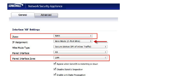
6. Select the Enable Link State Propagation option.
7. Select the Disable Stateful Inspection option.
8. Select the Bypass when SonicOS is restarting or down option.
9. Click the OK button.
To configure an interface for Tap Mode, perform the following steps:
1. On the Network > Interfaces page, click the Configure button for the interface you want to configure for Wire Mode.
2. In the Zone pulldown menu, select LAN.
3. To configure the Interface for Tap Mode, in the Mode / IP Assignment pulldown menu, select Tap Mode (1-Port Tap) and click OK.
To configure the Interface for Wire Mode, in the Mode / IP Assignment pulldown menu, select Wire Mode (2-Port Wire).
Click OK.
Perform the following steps to configure the WAN settings for the SonicWALL appliance.

1. Select how the WAN connects to the Internet from the IP Assignment list box:
• Static—Configure the following settings for static IP address interfaces:
– IP Address—Enter the IP address of the interface.
– Subnet Mask—Enter the subnet mask for the network.
– Default Gateway—IP address of the WAN gateway.
– DNS Server 1-3—IP addresses of the DNS Servers.
– Comment—Enter any comments regarding the interface.
• DHCP—Configure the following settings if the WAN IP address will use DHCP:
– Host Name—Specifies the host name of the SonicWALL device on the WAN interface.
– Comment—Enter any comments regarding the interface.
– IP Address, Subnet Mask, Gateway (Router) Address, and DNS Server 1-3—These settings are automatically filled in by DHCP.
• PPPoE—Configure the following settings if the WAN IP address will use PPPoE:
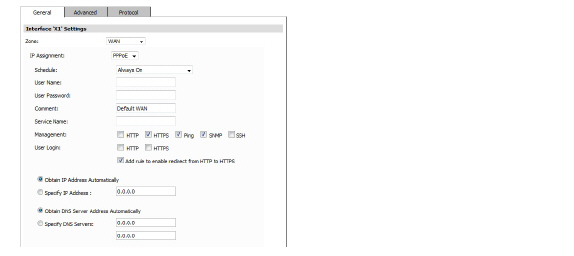
– Schedule—Select the schedule for when the interface is enabled. The default value is Always on. The available options can be customized in the System > Schedule page. The default choices are:
: •: Always on
: •: Work Hours or M-T-W-TH-F 08:00-17:00 (these two options are the same schedules)
: •: M-T-W-TH-F 00:00-08:00
: •: After Hours or M-T-W-TH-F 17:00-24:00 (these two options are the same schedules)
: •: Weekend Hours or SA-SU 00:00-24:00 (these two options are the same schedules)
– User Name—Enter username provided by the ISP.
– Password—Enter the password used to authenticate the username with the ISP. This field is case-sensitive.
– Comment—Enter any comments regarding the interface.
– Service Name—Enter the name of a service that must be supported by PPPoE servers that respond to a client connection request. The service name can be up to 50 characters. Many installations use the system name as a service name, for example “sonicwall-server” or “redback-server”. If the service name is left blank the client will connect to any service.
– Select from the following:
: •: To configure the SonicWALL appliance(s) to dynamically obtain an IP address, select Obtain an IP Address automatically.
: •: To configure the SonicWALL appliance(s) to use a fixed IP address, select Use the following IP Address and enter the IP address.
– Select from the following:
: •: To configure the SonicWALL appliance(s) to obtain the DNS server information automatically, select Obtain DNS Server Address Automatically.
: •: To specify DNS servers, select Specify DNS Servers and enter the DNS Server IP addresses.
Note For PPPoE interfaces, a Protocol tab appears that displays the acquired IP address, subnet mask, gateway address, and DNS server addresses.
– Click the Protocol tab.
– View the settings for the acquired IP address, subnet mask, gateway address, and DNS server addresses.
– Inactivity Disconnect—Specify how long (in minutes) the SonicWALL appliance waits before disconnecting from the Internet, and select the checkbox.
– Strictly use LCP echo packets for server keep-alive—This checkbox is enabled when the client recognizes that the server relies on Link Control Protocol (LCP) echo requests for keeping the PPPoE connection alive.
– Disconnect the PPPoE client if the server does not send traffic for __ minutes—Select this checkbox and enter the number of minutes to wait without traffic before the connection is ended. When enabled, the PPPoE client monitors traffic from the server on the tunnel and disconnects when no traffic is seen for the specified time period.
• PPTP—Configure the following settings if the WAN IP address will use PPTP:
– Schedule—Select the schedule for when the interface is enabled. The default value is Always on. The available options can be customized in the System > Schedules page. The default choices are:
: •: Always on
: •: Work Hours or M-T-W-TH-F 08:00-17:00 (these two options are the same schedules)
: •: M-T-W-TH-F 00:00-08:00
: •: After Hours or M-T-W-TH-F 17:00-24:00 (these two options are the same schedules)
: •: Weekend Hours or SA-SU 00:00-24:00 (these two options are the same schedules)
– User Name—Enter username provided by the ISP.
– User Password—Enter the password used to authenticate the username with the ISP. This field is case-sensitive.
– PPTP Server IP Address—this information is provided by your ISP.
– PPTP (Client) Host Name—this information is provided by your ISP.
– Comment—Enter any comments regarding the interface.
– Inactivity Disconnect—Specify how long (in minutes) the SonicWALL appliance waits before disconnecting from the Internet.
– Select from the following from the PPTP IP Assignment list box:
– To configure the SonicWALL appliance(s) to dynamically obtain an IP address, select DHCP.
– To configure the SonicWALL appliance(s) to use a fixed IP address, select Static and enter the IP address, subnet mask, and gateway IP address.
Note For PPTP interfaces, a Protocol tab appears that displays the acquired IP address, subnet mask, gateway address, and DNS server addresses.
• L2TP——Configure the following settings if the WAN IP address will use L2TP:
– Schedule—Select the schedule for when the interface is enabled. The default value is Always on. The available options can be customized in the System > Schedules page. The default choices are:
: •: Always on
: •: Work Hours or M-T-W-TH-F 08:00-17:00 (these two options are the same schedules)
: •: M-T-W-TH-F 00:00-08:00
: •: After Hours or M-T-W-TH-F 17:00-24:00 (these two options are the same schedules)
: •: Weekend Hours or SA-SU 00:00-24:00 (these two options are the same schedules)
– User Name—Enter username provided by the ISP.
– User Password—Enter the password used to authenticate the username with the ISP. This field is case-sensitive.
– L2TP Server IP Address—this information is provided by your ISP.
– L2TP (Client) Host Name—this information is provided by your ISP.
– Comment—Enter any comments regarding the interface.
– Inactivity Disconnect—Specify how long (in minutes) the SonicWALL appliance waits before disconnecting from the Internet.
– Select from the following from the L2TP IP Assignment list box:
: •: To configure the SonicWALL appliance(s) to dynamically obtain an IP address, select DHCP.
: •: To configure the SonicWALL appliance(s) to use a fixed IP address, select Static and enter the IP address, subnet mask, and gateway IP address.
Note For L2TP interfaces, a Protocol tab appears that displays the acquired IP address, subnet mask, gateway address, and DNS server addresses.
2. Select one or more of the following management options:
– HTTP—When selected, allows HTTP management from the interface.
– HTTPS—When selected, allows HTTPS management from the interface.
– Ping—When selected, the interface will respond to ping requests.
– SNMP—When selected, the interface will support Simple Network Management Protocol (SNMP).
3. User Login—Select from the following user login options:
– HTTP—When selected, users will be able to login using HTTP.
– HTTPS—When selected, users will be able to login using HTTPS.
– Add rule to enable redirect from HTTP to HTTPS—Redirects users to HTTPS when they attempt to access the device using HTTP. This option is only applicable when HTTPS access is enabled and HTTP access is not.
4. Click Update. The settings are saved. To clear any changes and start over, click Reset.
5. Click the Advanced tab and configure the following Ethernet settings:
– Link Speed—To configure the interface to automatically negotiate Ethernet settings, select Auto Negotiate. If you want to specify the forced Ethernet speed and duplex, select the appropriate setting.
– Override Default MAC Address—Select to manually enter the MAC address. Otherwise, the default MAC address is used.
– Enable Multicast Support—Select to enable multicast on the interface.
: •: Interface MTU—Specify the size of the Maximum Transmission Unit (MTU) in octets (default: 1500).
– To shutdown the port, click the Shutdown Port checkbox. A warning pop-up window displays, asking if you wish to administratively want to shut down the port.
Note This checkbox is only available for SuperMassive series appliances running SonicOS 6.1 and higher firmware images.
– To fragment packets that are larger than this MTU, select the Fragment non-VPN outbound packets larger than this Interface's MTU checkbox.
– To block notifications that this interface can receive fragmented packets, select the Do not send ICMP Fragmentation Needed for outbound packets over the Interface MTU checkbox.
Note If the maximum transmission unit (MTU) size is too large for a remote router, it may require more transmissions. If the packet size is too small, this could result in more packet header overhead and more acknowledgements that have to be processed.
– To ignore Don’t Fragment (DF) bits from routers connected to the SonicWALL appliance, select the Ignore Don't Fragment (DF) Bit check box.
Expert Mode
6. Under the Expert Mode Settings heading, select the Use Routed Mode - Add NAT Policy to prevent outbound\inbound translation checkbox to enable Routed Mode for the interface. Routed Mode provides an alternative for NAT for routing traffic between separate public IP address ranges. NAT translations will be automatically disabled for the interface, and all inbound and outbound traffic will be routed to the WAN interface
– In the Set NAT Policy's outbound\inbound interface to pull-down menu, select the WAN interface that is to be used to route traffic for the interface. The firewall then creates “no-NAT” policies for both the configured interface and the selected WAN interface. These policies override any more general M21 NAT policies that may be configured for the interfaces.
7. Click OK.
8. The firewall then creates “no-NAT” policies for both the configured interface and the selected WAN interface. These policies override any more general M21 NAT policies that may be configured for the interfaces.
The availability of Expert Mode depends on the zone and IP address assignment configuration of the interface, as follows:
• LAN & DMZ – Expert Mode is available for interfaces that are assigned a static IP address.
• WAN – Expert Mode is not available.
• WLAN - Expert Mode is available for all WLAN interfaces, regardless of IP assignment.
Bandwidth Management
SonicOS Enhanced can apply bandwidth management to both egress (outbound) and ingress (inbound) traffic on the interfaces in the WAN zone. Outbound bandwidth management is done using Class Based Queuing. Inbound Bandwidth Management is done by implementing ACK delay algorithm that uses TCP’s intrinsic behavior to control the traffic.
Class Based Queuing (CBQ) provides guaranteed and maximum bandwidth Quality of Service (QoS) for the SonicWALL security appliance. Every packet destined to the WAN interface is queued in the corresponding priority queue. The scheduler then dequeues the packets and transmits it on the link depending on the guaranteed bandwidth for the flow and the available link bandwidth.
Use the Bandwidth Management section of the Edit Interface screen to enable or disable the ingress and egress bandwidth management. Egress and Ingress available link bandwidth can be used to configure the upstream and downstream connection speeds in kilobits per second.
The Bandwidth Management settings are applied to all interfaces in the WAN zone, not just to the interface being configured.
• Enable Egress Bandwidth Management - Enables outbound bandwidth management.
– Available Interface Egress Bandwidth (Kbps) - Specifies the available bandwidth for WAN interfaces in Kbps.
• Enable Ingress Bandwidth Management - Enables inbound bandwidth management.
9. Available Interface Ingress Bandwidth (Kbps) - Specifies the available bandwidth for WAN interfaces in Kbps
10. Configure the following Bandwidth Management settings:
• To enable egress bandwidth management on this interface, select the check box and enter the bandwidth of the connection in the Available Interface Bandwidth field in kilobytes per second (Kbps).
• To enable ingress bandwidth management on this interface, select the check box and enter the bandwidth of the connection in the Available Interface Bandwidth field in kilobytes per second (Kbps).
11. Click Update. The settings are saved. To clear any changes and start over, click Reset.
Configuring Link Aggregation (SonicOS 5.9 or higher)
Link Aggregation groups up to four Ethernet interfaces together forming a single logical link to support greater throughput than a single physical interface could support, this is referred to as a Link Aggregation Group (LAG). This provides the ability to send multi-gigabit traffic between two Ethernet domains. All ports in an aggregate link must be connected to the same switch. The firewall uses a round-robin algorithm for load balancing traffic across the interfaces in a Link Aggregation Group. Link Aggregation also provides a measure of redundancy, in that if one interface in the LAG goes down, the other interfaces remain connected.
Link Aggregation is referred to using different terminology by different vendors, including Port Channel, Ether Channel, Trunk, and Port Grouping.
Link Aggregation failover
SonicWALL provides multiple methods for protecting against loss of connectivity in the case of a link failure, including High Availability (HA), Load Balancing Groups (LB Groups), and now Link Aggregation. If all three of these features are configured on a firewall, the following order of precedence is followed in the case of a link failure:
1. High Availability
2. Link Aggregation
3. Load Balancing Groups
HA takes precedence over Link Aggregation. Because each link in the LAG carries an equal share of the load, the loss of a link on the Active firewall will force a failover to the Idle firewall (if all of its links remain connected). Physical monitoring needs to be configured only on the primary aggregate port.
When Link Aggregation is used with a LB Group, Link Aggregation takes precedence. LB will take over only if all the ports in the aggregate link are down.
Link Aggregation Limitations
• Currently only static addressing is supported for Link Aggregation
• Link Aggregation is supported on Dell SonicWALL E-Class appliances only.
• The Link Aggregation Control Protocol (LACP) is currently not supported
Link Aggregation Configuration
To configure Link Aggregation, perform the following tasks:
1. On the Network > Interfaces page, click the configure icon for the interface that is to be designated the master of the Link Aggregation Group. The Edit Interface window displays.
2. In the General tab, select a zone from the Zone pull-down menu.
3. Click on the Advanced tab.

4. In the Redundant/Aggregate Ports pull-down menu, select Link Aggregation.
5. The Aggregate Port option is displayed with a checkbox for each of the currently unassigned interfaces on the firewall. Select up to three other interfaces to assign to the LAG.
6. (Wire Mode only) The Paired Interface Aggregate Port option is displayed, select up to three paired interfaces.
Note After an interface is assigned to a Link Aggregation Group, its configuration is governed by the Link Aggregation master interface and it cannot be configured independently. In the Interface Settings table, the interface's zone is displayed as "Aggregate Port" and the configuration icon is removed.
7. Set the Link Speed for the interface to Auto-Negotiate.
8. Click OK.
Note Link Aggregation requires a matching configuration on the Switch. The switch's method of load balancing will very depending on the vendor. Consult the documentation for the switch for information on configuring Link Aggregation. Remember that it may be referred to as Port Channel, Ether Channel, Trunk, or Port Grouping.
Port Redundancy (SonicOS 5.9 or higher)
Port Redundancy provides a simple method for configuring a redundant port for a physical Ethernet port. This is a valuable feature, particularly in high-end deployments, to protect against switch failures being a single point of failure.
When the primary interface is active, it processes all traffic to and from the interface. If the primary interface goes down, the secondary interface takes over all outgoing and incoming traffic. The secondary interface assumes the MAC address of the primary interface and sends the appropriate gratuitous ARP on a failover event. When the primary interface comes up again, it resumes responsibility for all traffic handling duties from the secondary interface.
In a typical Port Redundancy configuration, the primary and secondary interfaces are connected to different switches. This provides for a failover path in case the primary switch goes down. Both switches must be on the same Ethernet domain. Port Redundancy can also be configured with both interfaces connected to the same switch.
Note: Port Redundancy is supported on Dell SonicWALL E-Class appliances only.
Port Redundancy Failover
SonicWALL provides multiple methods for protecting against loss of connectivity in the case of a link failure, including High Availability (HA), Load Balancing Groups (LB Groups), and now Port Redundancy. If all three of these features are configured on a firewall, the following order of precedence is followed in the case of a link failure:
1. Port Redundancy
2. HA
3. LB Group
When Port Redundancy is used with HA, Port Redundancy takes precedence. Typically an interface failover will cause an HA failover to occur, but if a redundant port is available for that interface, then an interface failover will occur but not an HA failover. If both the primary and secondary redundant ports go down, then an HA failover will occur (assuming the secondary firewall has the corresponding port active).
When Port Redundancy is used with a LB Group, Port Redundancy again takes precedence. Any single port (primary or secondary) failures are handled by Port Redundancy just like with HA. When both the ports are down then LB kicks in and tries to find an alternate interface.
Port Redundancy Configuration
To configure Port Redundancy, perform the following tasks:
1. On the Network > Interfaces page, click the configure icon for the interface that is to be designated the master of the Link Aggregation Group. The Edit Interface window displays.
2. In the General tab, select a zone from the Zone pull-down menu.
3. Click on the Advanced tab.
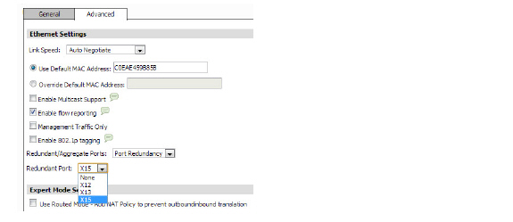
4. In the Redundant/Aggregate Ports pull-down menu, select Port Redundancy.
5. The Redundant Port pull-down menu is displayed, with all of the currently unassigned interfaces available. Select one of the interfaces.
Note After an interface is selected as a Redundant Port, its configuration is governed by the primary interface and it can not be configured independently. In the Interface Settings table, the interface's zone is displayed as "Redundant Port" and the configuration icon is removed.
6. Set the Link Speed for the interface to Auto-Negotiate.
7. Click OK.
Configuring VLAN Sub-Interfaces
When you add a VLAN sub-interface, you need to assign it to a Zone, assign it a VLAN Tag, and assign it to a physical interface. Based on your zone assignment, you configure the VLAN sub-interface the same way you configure a physical interface for the same zone.
1. At the bottom of the Network > Interfaces page, click Add VLAN Interface. The Add Interface window displays.

2. Select a Zone to assign to the interface. You can select LAN, DMZ, WLAN, or unassigned. The zone assignment does not have to be the same as the parent (physical) interface.
3. Enter a Portshield Interface Name for the sub-interface.
4. Declare the parent (physical) interface to which this sub-interface will belong. There is no per-interface limit to the number of sub-interfaces you can assign – you may assign sub-interfaces up to the system limit (in the hundreds).
5. For LAN and DMZ, select Static or Transparent for the IP Assignment. WLAN interfaces use static IP addresses:
– For static IP addresses, enter the IP Address for the interface and Subnet Mask for the network.
– For transparent mode, select an address object that contains the range of IP addresses you want to have access through this interface in the Transparent Range menu.
6. Management—Select from the following management options:
– HTTP—When selected, allows HTTP management from the interface.
– HTTPS—When selected, allows HTTPS management from the interface.
– Ping—When selected, the interface will respond to ping requests.
– SNMP—When selected, the interface will support Simple Network Management Protocol (SNMP).
7. User Login—Select from the following user login options:
– HTTP—When selected, users will be able to login using HTTP.
– HTTPS—When selected, users will be able to login using HTTPS.
– Add rule to enable redirect from HTTP to HTTPS—Redirects users to HTTPS when they attempt to access the device using HTTP. This option is only applicable when HTTPS access is enabled and HTTP access is not.
8. Check Create Default DHCP Lease Scope to indicate that the amount of time allowed for an IP address issued by DHCP will be the default.
9. Click OK.
The Virtual interface displays in the VLAN Interfaces table below the Interfaces table.
To configure the WAN connection model for a SonicWALL appliance with WWAN capability running SonicOS Enhanced 3.6 or higher, navigate to the Network > Interfaces page and select one of the following options in the WAN Connection Model pull-down menu:
• WWAN only—The WAN interface is disabled and the WWAN interface is used exclusively.
• Ethernet only—The WWAN interface is disabled and the WAN interface is used exclusively.
• Ethernet with WWAN Failover—The WAN interface is used as the primary interface and the WWAN interface is disabled. If the WAN connection fails, the WWAN interface is enabled and a WWAN connection is automatically initiated.
Note The Wan Connection Model option does not apply to TZ200 through NSA240 units running SonicOS Enhanced 5.6 and above. For these devices, any WWAN interfaces are treated as a regular WAN interface and failover to the WWAN is configured as a secondary WAN interface. See the Configuring Multiple WAN Interfaces for more information.
To initiate a WWAN connection, perform the following steps:
1. In the Interface Settings table, in the WWAN row, click Connect. The SonicWALL appliance attempts to connect to the WWAN service provider.
2. To disconnect a WWAN connection, click Disconnect.
To configure an interface for Management (MGMT) mode, perform the following:
1. Click on the Configure icon ![]() in the Configure column for the Interface you want to configure. The Edit Interface window is displayed.
in the Configure column for the Interface you want to configure. The Edit Interface window is displayed.
2. Click the Zone drop-down menu, select MGMT.
3. Select Static from the IP Assignment menu.
4. Enter the IP address and subnet mask of the zone in the IP Address and Subnet Mask fields.
Note You cannot enter an IP address that is in the same subnet as another zone.
5. Enter an IP address for a Default Gateway (optional). This feature is not supported for WLAN and VPN zones.
6. Enter any optional comment text in the Comment field. This text is displayed in the Comment column of the Interface table.
7. If you want to enable remote management of the SonicWALL appliance from this interface, select the supported management protocol(s): HTTP, HTTPS, SSH, Ping, SNMP, and/or SSH.
8. If you want to allow selected users with limited management rights to log in to the security appliance, select HTTP and/or HTTPS in User Login.
9. Click OK.