Third_Party_Gateway
Configuring the SRA Appliance with a Third-Party Gateway
Cisco PIX Configuration for SRA Appliance Deployment
• Netgear Wireless Router MR814 SSL configuration
Cisco PIX Configuration for SRA Appliance Deployment
Make sure you have a management connection to the PIX’s console port, or the ability to Telnet/SSH into one of the PIX’s interfaces. You will need to know the PIX’s global and enable-level passwords in order to access the device and issue changes to the configuration. If you do not have these, contact your network administrator before continuing.
Dell SonicWALL recommends updating the PIX’s OS to the most recent version if your PIX can support it. This document was validated on a Cisco PIX 515e running PIX OS 6.3.5 and is the recommended version for interoperation with a SRA appliance. You will need a valid Cisco SmartNET maintenance contract for your Cisco PIX and a CCO login to obtain newer versions of the PIX OS.
Note The WAN/DMZ/LAN IP addresses used in the deployment method examples below are not valid and will need to be modified to reflect your networking environment.
Management Considerations for the Cisco Pix
Both deployment methods described below use the PIX’s WAN interface IP address as the means of external connectivity to the internal SRA appliance. The PIX has the ability to be managed via HTTP/S, but cannot have their default management ports (80,443) reassigned in the recommended PIX OS version. Because of this, the HTTP/S management interface must be deactivated. To deactivate the HTTP/S management interface, issue the command ‘clear http’.
Note If you have a separate static WAN IP address to assign to the SRA appliance, you do not have to deactivate the HTTP/S management interface on the PIX.
Method One – SRA Appliance on LAN Interface
1. From a management system, log into the SRA appliance’s management interface. By default the management interface is X0 and the default IP address is 192.168.200.1.
2. Navigate to the Network > Interfaces page and click on the configure icon for the X0 interface. On the pop-up that appears, change the X0 address to 192.168.100.2 with a mask of 255.255.255.0. When done, click on the OK button to save and activate the change.
3. Navigate to the Network > Routes page and change the Default Gateway to 192.168.100.1 When done, click on the Accept button in the upper-right-hand corner to save and activate the change.
4. Navigate to the NetExtender > Client Addresses page. You will need to enter a range of IP addresses for the 192.168.100.0/24 network that are not in use on your internal LAN network; if your network has an existing DHCP server or the PIX is running a DHCP server on its internal interface, you will need to make sure not to conflict with these addresses. For example: enter 192.168.100.201 in the field next to Client Address Range Begin:, and enter 192.168.100.249 in the field next to Client Address Range End:. When done, click on the Accept button in the upper-right-hand corner to save and activate the change.
5. Navigate to the NetExtender > Client Routes page. Add a client route for 192.168.100.0. If there is an entry for 192.168.200.0, delete it.
6. Navigate to the Network > DNS page and enter your internal network’s DNS addresses, internal domain name, and WINS server addresses. These are critical for NetExtender to function correctly. When done, click on the Accept button in the upper-right-hand corner to save and activate the change.
7. Navigate to the System > Restart page and click on the Restart… button.
8. Install the SRA appliance’s X0 interface on the LAN network of the PIX. Do not hook any of the appliance’s other interfaces up.
9. Connect to the PIX’s management CLI via console port, telnet, or SSH and enter configure mode.
10. Issue the command ‘clear http’ to shut off the PIX’s HTTP/S management interface.
11. Issue the command ‘access-list sslvpn permit tcp any host x.x.x.x eq www’ (replace x.x.x.x with the WAN IP address of your PIX)
12. Issue the command ‘access-list sslvpn permit tcp any host x.x.x.x eq https’ (replace x.x.x.x with the WAN IP address of your PIX)
13. Issue the command ‘static (inside,outside) tcp x.x.x.x www 192.168.100.2 www netmask 255.255.255.255 0 0’ (replace x.x.x.x with the WAN IP address of your PIX)
14. Issue the command ‘static (inside,outside) tcp x.x.x.x https 192.168.100.2 https netmask 255.255.255.255 0 0’ (replace x.x.x.x with the WAN IP address of your PIX)
15. Issue the command ‘access-group sslvpn in interface outside’
16. Exit config mode and issue the command ‘wr mem’ to save and activate the changes.
17. From an external system, attempt to connect to the SRA appliance using both HTTP and HTTPS. If you cannot access the SRA appliance, check all steps above and test again.
Final Config Sample – Relevant Programming in Bold:
PIX Version 6.3(5)
interface ethernet0 auto
interface ethernet1 auto
interface ethernet2 auto shutdown
nameif ethernet0 outside security0
nameif ethernet1 inside security100
nameif ethernet2 dmz security4
enable password SqjOo0II7Q4T90ap encrypted
passwd SqjOo0II7Q4T90ap encrypted
hostname tenaya
domain-name vpntestlab.com
clock timezone PDT -8
clock summer-time PDT recurring
fixup protocol dns maximum-length 512
fixup protocol ftp 21
fixup protocol h323 h225 1720
fixup protocol h323 ras 1718-1719
fixup protocol http 80
fixup protocol rsh 514
fixup protocol rtsp 554
fixup protocol sip 5060
fixup protocol sip udp 5060
fixup protocol skinny 2000
fixup protocol smtp 25
fixup protocol sqlnet 1521
fixup protocol tftp 69
names
access-list sslvpn permit tcp any host 64.41.140.167 eq www
access-list sslvpn permit tcp any host 64.41.140.167 eq https
pager lines 24
logging on
logging timestamp
logging buffered warnings
logging history warnings
mtu outside 1500
mtu inside 1500
mtu dmz 1500
ip address outside 64.41.140.167 255.255.255.224
ip address inside 192.168.100.1 255.255.255.0
no ip address dmz
ip audit info action alarm
ip audit attack action alarm
pdm history enable
arp timeout 14400
global (outside) 1 interface
nat (inside) 1 192.168.100.0 255.255.255.0 0 0
static (inside,outside) tcp 64.41.140.167 www 192.168.100.2 www netmask 255.255.255.255 0 0
static (inside,outside) tcp 64.41.140.167 https 192.168.100.2 https netmask 255.255.255.255 0 0
access-group sslvpn in interface outside
route outside 0.0.0.0 0.0.0.0 64.41.140.166 1
timeout xlate 3:00:00
timeout conn 1:00:00 half-closed 0:10:00 udp 0:02:00 rpc 0:10:00 h225 1:00:00
timeout h323 0:05:00 mgcp 0:05:00 sip 0:30:00 sip_media 0:02:00
timeout sip-disconnect 0:02:00 sip-invite 0:03:00
timeout uauth 0:05:00 absolute
aaa-server TACACS+ protocol tacacs+
aaa-server TACACS+ max-failed-attempts 3
aaa-server TACACS+ deadtime 10
aaa-server RADIUS protocol radius
aaa-server RADIUS max-failed-attempts 3
aaa-server RADIUS deadtime 10
aaa-server LOCAL protocol local
ntp server 192.43.244.18 source outside prefer
no snmp-server location
no snmp-server contact
snmp-server community SF*&^SDG
no snmp-server enable traps
floodguard enable
telnet 0.0.0.0 0.0.0.0 inside
telnet timeout 15
ssh 0.0.0.0 0.0.0.0 outside
ssh 0.0.0.0 0.0.0.0 inside
ssh timeout 15
console timeout 20
dhcpd address 192.168.100.101-192.168.100.199 inside
dhcpd dns 192.168.100.10
dhcpd lease 600
dhcpd ping_timeout 750
dhcpd domain vpntestlab.com
dhcpd enable inside
terminal width 80
banner motd Restricted Access. Please log in to continue.
Cryptochecksum:422aa5f321418858125b4896d1e51b89
: end
tenaya#
Method Two – SRA Appliance on DMZ Interface
This method is optional and requires that the PIX have an unused third interface, such as a PIX 515, PIX 525, or PIX 535. We will be using the default numbering scheme of the SRA appliance.
1. From a management system, log into the SRA appliance’s management interface. By default the management interface is X0 and the default IP address is 192.168.200.1.
2. Navigate to the Network > Routes page and make sure the Default Gateway is set to 192.168.200.2 When done, click on the Accept button in the upper-right-hand corner to save and activate the change.
3. Navigate to the NetExtender > Client Addresses page. Enter 192.168.200.201 in the field next to Client Address Range Begin:, and enter 192.168.200.249 in the field next to Client Address Range End:’. When done, click on the Accept button in the upper-right-hand corner to save and activate the change.
4. Navigate to the NetExtender > Client Routes page. Add a client route for 192.168.100.0 and 192.168.200.0.
5. Navigate to the Network > DNS page and enter your internal network’s DNS addresses, internal domain name, and WINS server addresses. These are critical for NetExtender to function correctly. When done, click on the Accept button in the upper-right-hand corner to save and activate the change.
6. Navigate to the System > Restart page and click on the Restart… button.
7. Install the SRA appliance’s X0 interface on the unused DMZ network of the PIX. Do not hook any of the appliance’s other interfaces up.
8. Connect to the PIX’s management CLI via console port, telnet, or SSH and enter configure mode.
9. Issue the command ‘clear http’ to shut off the PIX’s HTTP/S management interface.
10. Issue the command ‘interface ethernet2 auto’ (or whatever interface you will be using)
11. Issue the command ‘nameif ethernet2 dmz security4’ (or whatever interface you will be using)
12. Issue the command ‘ip address dmz 192.168.200.2 255.255.255.0’
13. Issue the command ‘nat (dmz) 1 192.168.200.0 255.255.255.0 0 0’
14. Issue the command ‘access-list sslvpn permit tcp any host x.x.x.x eq www’ (replace x.x.x.x with the WAN IP address of your PIX)
15. Issue the command ‘access-list sslvpn permit tcp any host x.x.x.x eq https’ (replace x.x.x.x with the WAN IP address of your PIX)
16. Issue the command ‘access-list dmz-to-inside permit ip 192.168.200.0 255.255.255.0 192.168.100.0 255.255.255.0’
17. Issue the command ‘access-list dmz-to-inside permit ip host 192.168.200.1 any’
18. Issue the command ‘static (dmz,outside) tcp x.x.x.x www 192.168.200.1 www netmask 255.255.255.255 0 0’ (replace x.x.x.x with the WAN IP address of your PIX)
19. Issue the command ‘static (dmz,outside) tcp x.x.x.x https 192.168.200.1 https netmask 255.255.255.255 0 0’ (replace x.x.x.x with the WAN IP address of your PIX)
20. Issue the command ‘static (inside,dmz) 192.168.100.0 192.168.100.0 netmask 255.255.255.0 0 0’
21. Issue the command ‘access-group sslvpn in interface outside’
22. Issue the command ‘access-group dmz-to-inside in interface dmz’
23. Exit config mode and issue the command ‘wr mem’ to save and activate the changes.
24. From an external system, attempt to connect to the SRA appliance using both HTTP and HTTPS. If you cannot access the SRA appliance, check all steps above and test again.
Final Config Sample – Relevant Programming in Bold:
PIX Version 6.3(5)
interface ethernet0 auto
interface ethernet1 auto
interface ethernet2 auto
nameif ethernet0 outside security0
nameif ethernet1 inside security100
nameif ethernet2 dmz security4
enable password SqjOo0II7Q4T90ap encrypted
passwd SqjOo0II7Q4T90ap encrypted
hostname tenaya
domain-name vpntestlab.com
clock timezone PDT -8
clock summer-time PDT recurring
fixup protocol dns maximum-length 512
fixup protocol ftp 21
fixup protocol h323 h225 1720
fixup protocol h323 ras 1718-1719
fixup protocol http 80
fixup protocol rsh 514
fixup protocol rtsp 554
fixup protocol sip 5060
fixup protocol sip udp 5060
fixup protocol skinny 2000
fixup protocol smtp 25
fixup protocol sqlnet 1521
fixup protocol tftp 69
names
access-list sslvpn permit tcp any host 64.41.140.167 eq www
access-list sslvpn permit tcp any host 64.41.140.167 eq https
access-list dmz-to-inside permit ip 192.168.200.0 255.255.255.0 192.168.100.0 255.255.255.0
access-list dmz-to-inside permit ip host 192.168.200.1 any
pager lines 24
logging on
logging timestamp
logging buffered warnings
mtu outside 1500
mtu inside 1500
mtu dmz 1500
ip address outside 64.41.140.167 255.255.255.224
ip address inside 192.168.100.1 255.255.255.0
ip address dmz 192.168.200.2 255.255.255.0
ip audit info action alarm
ip audit attack action alarm
pdm history enable
arp timeout 14400
global (outside) 1 interface
nat (inside) 1 192.168.100.0 255.255.255.0 0 0
nat (dmz) 1 192.168.200.0 255.255.255.0 0 0
static (dmz,outside) tcp 64.41.140.167 www 192.168.200.1 www netmask 255.255.255.255 0 0
static (dmz,outside) tcp 64.41.140.167 https 192.168.200.1 https netmask 255.255.255.255 0 0
static (inside,dmz) 192.168.100.0 192.168.100.0 netmask 255.255.255.0 0 0
access-group sslvpn in interface outside
access-group dmz-to-inside in interface dmz
route outside 0.0.0.0 0.0.0.0 64.41.140.166 1
timeout xlate 3:00:00
timeout conn 1:00:00 half-closed 0:10:00 udp 0:02:00 rpc 0:10:00 h225 1:00:00
timeout h323 0:05:00 mgcp 0:05:00 sip 0:30:00 sip_media 0:02:00
timeout sip-disconnect 0:02:00 sip-invite 0:03:00
timeout uauth 0:05:00 absolute
aaa-server TACACS+ protocol tacacs+
aaa-server TACACS+ max-failed-attempts 3
aaa-server TACACS+ deadtime 10
aaa-server RADIUS protocol radius
aaa-server RADIUS max-failed-attempts 3
aaa-server RADIUS deadtime 10
aaa-server LOCAL protocol local
ntp server 192.43.244.18 source outside prefer
floodguard enable
telnet 0.0.0.0 0.0.0.0 inside
telnet timeout 15
ssh 0.0.0.0 0.0.0.0 outside
ssh timeout 15
console timeout 20
dhcpd address 192.168.100.101-192.168.100.199 inside
dhcpd dns 192.168.100.10
dhcpd lease 600
dhcpd ping_timeout 750
dhcpd domain vpntestlab.com
dhcpd enable inside
terminal width 80
banner motd Restricted Access. Please log in to continue.
Cryptochecksum:81330e717bdbfdc16a140402cb503a77
: end
The SRA appliance should be configured on the LAN switch of the Linksys wireless router. This guide assumes that your Linksys is assigned a single WAN IP, via DHCP by the cable ISP and is using the default LAN IP address scheme of 192.168.1.0/24.
Note Version 2.07.1 Firmware or newer is recommended for this setup.
To configure your Linksys for operation with the SRA appliance, you must forward the SSL (443) port to the IP address of the SRA appliance.
1. Login to the Linksys device.
2. Navigate to the Applications & Gaming tab.
3. Enter the following information:
|
4. : With the configuration complete, click the Save Settings button on the bottom of the page.
The Linksys is now ready for operations with the SRA appliance.
This guide assumes that your WatchGuard Firebox X Gateway is configured with an IP of 192.168.100.1 and your SRA appliance is configured with an IP of 192.168.100.2.
Note The steps below are similar for WatchGuard SOHO6 series firewall.
Before you get started, take note of which port the WatchGuard is using for management. If the WatchGuard is not being managed on HTTPS (443), perform the following steps. If the WatchGuard is being managed on HTTPS (443) you’ll need to first review the notes within this guide.
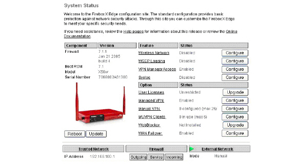
1. Open browser and enter the IP address of the WatchGuard Firebox X Edge appliance (i.e. 192.168.100.1). Once successful, you’ll be brought to the “System Status” page (below).
2. If the WatchGuard’s management interface is already configured to accept HTTPS on port 443 you will need to change the port in order to be able to manage both the Dell SonicWALL SRA and WatchGuard appliances.
3. Navigate to Administration > System Security.
Figure 1: WatchGuard Administration > System Security Dialog Box
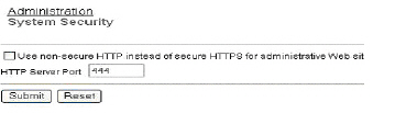
4. Clear the Use non-secure HTTP instead of secure HTTPS for administrative Web site check box.
5. Change the HTTP Server Port to 444 and click the Submit button.
The WatchGuard will now be managed from the WAN on port 444. It should be accessed as follows: https://<watchguard wan ip>:444
6. In the left-hand navigation menu, Navigate to Firewall > Incoming.
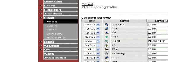
7. For the HTTPS Service, set Filter to Allow and enter the WAN IP of the SRA appliance (192.168.100.2) in the Service Host field.
8. Click the Submit button at the bottom of the page.
Your Watchguard Firebox X Edge is now ready for operations with the SRA appliance.
This guide assumes that your NetGear FVS318 Gateway is configured with an IP of 192.168.100.1 and your SRA appliance is configured with an IP of 192.168.100.2.
1. Click Remote Management from the left-hand index of your Netgear management interface.
In order for the SRA appliance to function with your Netgear gateway device, you must verify that the NetGear’s management port will not conflict with the management port used by the SRA appliance.
2. Clear the Allow Remote Management box.
3. Click the Accept button to save changes.
Note If Remote Management of the NetGear is desired, you must leave the box checked and change the default port (8080 is recommended)
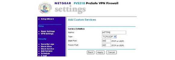
4. Navigate to Add Service in the left-hand navigation.
5. Click the Add Custom Service button.
6. To create a service definition, enter the following information:
|
7. Navigate to Ports in the left-hand navigation.
8. Click the Add button.
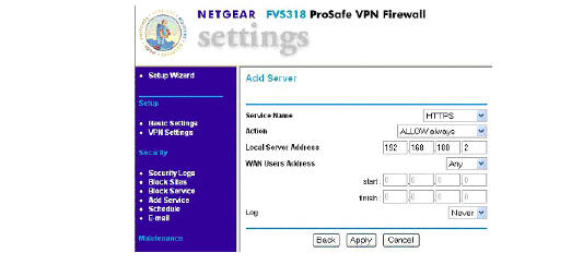
9. Select HTTPS from the Service Name drop-down list.
10. Select ALLOW always in the Action drop-down list.
11. Enter the WAN IP address of the SRA appliance (ex.192.168.100.2) in the Local Server Address field.
12. Click Accept to save changes.
Your Netgear gateway device is now ready for operations with the SRA appliance.
Netgear Wireless Router MR814 SSL configuration
This guide assumes that your NetGear Wireless Router is configured with an IP of 192.168.100.1 and your SRA appliance is configured with an IP of 192.168.100.2.
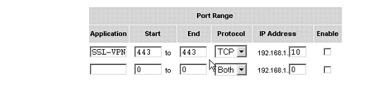
1. Navigate to Advanced > Port Management in the left-hand index of your Netgear management interface.
2. Click the Add Custom Service button in the middle of the page.
3. Enter a service name in the Service Name field (ex. SRA)
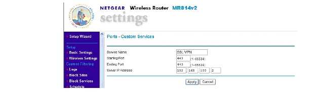
4. Enter 443 in the Starting Port field.
5. Enter 443 in the Ending Port field.
6. Enter the WAN IP address of the SRA appliance (ex.192.168.100.2) in the Local Server Address field.
7. Click the Accept button
Your Netgear wireless router is now ready for operations with the SRA appliance.
Setting up an SRA Appliance with Check Point AIR 55
The first thing necessary to do is define a host-based network object. This is done under the file menu “Manage” and “Network Objects”.
Figure B:28 Check Point Host Node Object Dialog Box
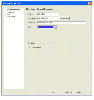
Note The object is defined as existing on the internal network. Should you decide to locate the SRA appliance on a secure segment (sometimes known as a demilitarized zone) then subsequent firewall rules will have to pass the necessary traffic from the secure segment to the internal network.
Next, select the NAT tab for the object you have created.
Figure B:29 Check Point NAT Properties Dialog Box

Here you will enter the external IP address (if it is not the existing external IP address of the firewall). The translation method to be selected is static. Clicking OK will automatically create the necessary NAT rule shown below.
Figure B:30 Check Point NAT Rule Window

Most installations of Check Point AIR55 require a static route. This route will send all traffic from the public IP address for the SRA appliance to the internal IP address.
#route add 64.41.140.167 netmask 255.255.255.255 192.168.100.2
Check Point AIR55 contains a feature called auto-ARP creation. This feature will automatically add an ARP entry for a secondary external IP address (the public IP address of the SRA appliance). If running Check Point on a Nokia security platform, Nokia recommends that users disable this feature. As a result, the ARP entry for the external IP address must be added manually within the Nokia Voyager interface.
Finally, a traffic or policy rule is required for all traffic to flow from the Internet to the SRA appliance.
Figure B:31 Check Point Policy Rule Window
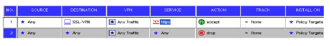
Again, should the SRA appliance be located on a secure segment of the Check Point firewall, a second rule allowing the relevant traffic to flow from the SRA appliance to the internal network will be necessary.