|
1
|
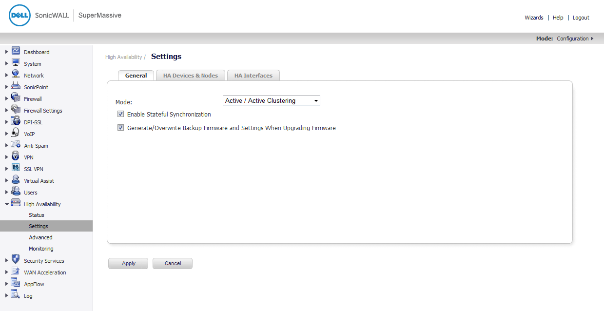
Login to the Primary unit of the Master Cluster Node and navigate to the High Availability > Settings page. The General tab is displayed.
|
|
2
|
In the Mode drop-down menu, select Active/Active Clustering.
|
|
3
|
Select the Enable Stateful Synchronization option.
|
|
4
|
Select the Generate/Overwrite Secondary Firmware and Settings When Upgrading Firmware option to automatically create a secondary of the firmware and configuration settings when you upload new firmware to the appliance. As the Master Node synchronizes new firmware to other appliances in the cluster, secondary units are created on those appliances.
|
|
5
|
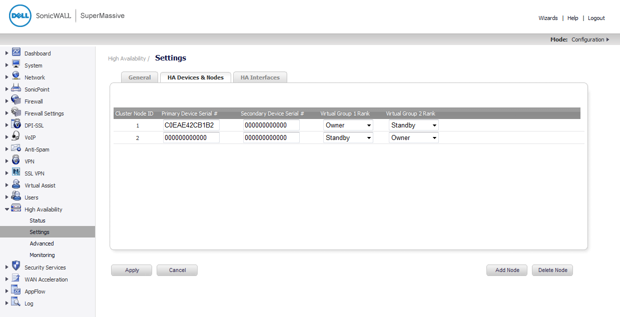
Click the HA Devices & Nodes tab to configure the Active/Active cluster information.
|
|
7
|
Enter the rank that Cluster Node 1 holds for each Virtual Group in the Virtual Group X Rank fields to the right of the serial numbers. By default, Cluster Node 1 is the Owner of Group 1, and typically is ranked as Standby for Group 2. To exclude an appliance from a cluster, select None for the Virtual Group X Rank.
|
|
8
|
In the second row, enter the rank that Cluster Node 2 holds for each Virtual Group in the Virtual Group X Rank fields to the right of the serial numbers.
|
|
9
|
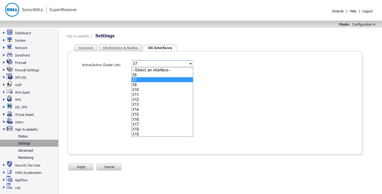
Click the HA Interfaces tab. Select the interface you want for the Active/Active Cluster Link interface. This interface will be used for transferring data between the two units during Active/Active processing. Only unassigned, available interfaces appear in the list.
|
|
10
|
When finished with all High Availability configuration, click Apply. All settings will be synchronized to the Standby unit, and the Standby unit will reboot.
|
|
11
|
Go to the High Availability > Monitoring page and follow the steps in Configuring Active/Active Clustering High Availability Monitoring .
|
|
12
|
|
13
|
Go to the Network > Interfaces page to verify that you have successfully configured the Active/Active interfaces that you want.
|
|
14
|
Go to the High Availability > Status page to verify your settings for Active/Active Clustering.
|
The configuration tasks on the High Availability > Monitoring page are performed on the Primary unit and then are automatically synchronized to the Secondary. These settings only affect the HA pair in the Cluster Node that is selected at the top of the page.

|
2
|
In the left navigation pane, navigate to High Availability > Monitoring.
|
|
3
|
At the top right side of the page, select the node to configure from the drop-down list.
|
|
4
|
Click the Configure icon for an interface on the LAN, such as X0.
|
|
5
|
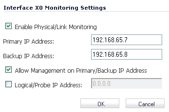
To enable link detection between the designated HA interfaces on the Primary and Secondary units, leave the Enable Physical Interface Monitoring checkbox selected.
|
|
6
|
In the Primary IP Address field, enter the unique LAN management IP address of the Primary unit.
|
|
7
|
In the Secondary IP Address field, enter the unique LAN management IP address of the Secondary unit.
|
|
8
|
Select the Allow Management on Primary/Secondary IP Address checkbox. When this option is enabled for an interface, a green icon appears in the interface’s Management column in the Monitoring Settings table on the High Availability > Monitoring page. Management is only allowed on an interface when this option is enabled.
|
|
9
|
In the Logical Probe IP Address field, enter the IP address of a downstream device on the LAN network that should be monitored for connectivity. Typically, this should be a downstream router or server. (If probing is desired on the WAN side, an upstream device should be used.) The Primary and Secondary appliances will regularly ping this probe IP address. If both can successfully ping the target, no failover occurs. If neither can successfully ping the target, no failover occurs, because it is assumed that the problem is with the target, and not the firewalls. But, if one appliance can ping the target and the other appliance cannot, failover will occur to the appliance that can ping the target.
|
The Primary IP Address and Secondary IP Address fields must be configured with independent IP addresses on a LAN interface, such as X0, (or a WAN interface, such as X1, for probing on the WAN) to allow logical probing to function correctly.
|
10
|
Click OK.
|
|
12
|
When finished with all High Availability monitoring configuration for the selected Cluster Node, click Apply. Then select a different Cluster Node and repeat the configuration steps and then click Apply.
|
For additional information on verifying the configuration, see Verifying Active/Active Clustering Configuration .
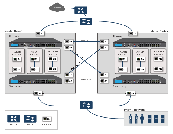
Figure 59. Active/Active DPI clustering high availability
|
1
|
Login to the Primary unit of the Master Cluster Node and navigate to the High Availability > Settings page. The General tab is displayed.
|
If you have physically connected the Active/Active DPI Interface as described in Physically Connecting Your Appliances , you are ready to configure Active/Active DPI in the SonicOS management interface.
|
2
|
|
3
|
The Enable Stateful Synchronization option is automatically enabled for Active/Active DPI Clustering.
|
|
4
|
Select the Generate/Overwrite Secondary Firmware and Settings When Upgrading Firmware checkbox to automatically create a secondary of the firmware and configuration settings when yo upload new firmware to the appliance. As the Master Node synchronizes new firmware to other appliances in the cluster, secondarys will be created on those appliances.
|
|
5
|
Click the HA Devices tab to configure the Active/Active cluster information.
|
|
6
|
For the HA Secondary option at the top of the tab, select Internal if the configured secondary appliance is part of the cluster node for this appliance. Select External if the configured secondary appliance is part of a different cluster node.
|
|
8
|
Enter the rank that Cluster Node 1 holds for each Virtual Group in the Virtual Group X Rank fields to the right of the serial numbers. By default, Cluster Node 1 is the Owner of Group 1, and typically is ranked as Standby for Group 2. To exclude an appliance from a cluster, select None for the Virtual Group X Rank.
|
|
9
|
In the second row, enter the rank that Cluster Node 2 holds for each Virtual Group in the Virtual Group X Rank fields to the right of the serial numbers.
|
|
10
|
Click the HA Interfaces tab. Select the interface for the HA Control Interface. This option is grayed out if the appliance detects that the interface is already configured.
|
|
11
|
Select the interface for the Active/Active DPI Interface.This option is grayed out if the appliance detects that the interface is already configured.
|
|
12
|
Select the Active/Active DPI Interface. This interface will be used for transferring data between the two units during Active/Active DPI processing. Only unassigned, available interfaces appear in the list.
|
|
13
|
Select the Active/Active Cluster Link interface.
|
|
14
|
When finished with all High Availability configuration, click Apply. All settings will be synchronized to the Standby unit, and the Standby unit will reboot.
|
|
15
|
Go to the High Availability > Monitoring page and follow the steps in Configuring Active/Active Clustering High Availability Monitoring .
|
|
16
|
|
17
|
Go to the Network > Interfaces page to verify that you have successfully configured the Active/Active interfaces that you want.
|
|
18
|
Go to the High Availability > Status page to verify your settings for Active/Active Clustering.
|
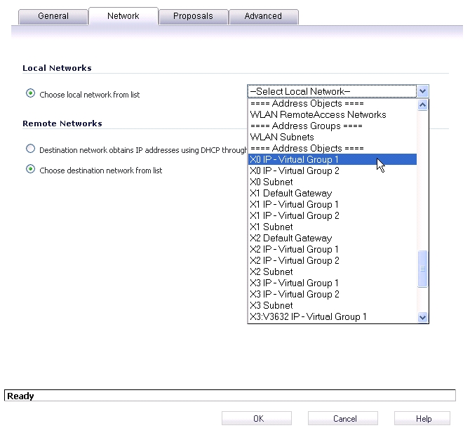
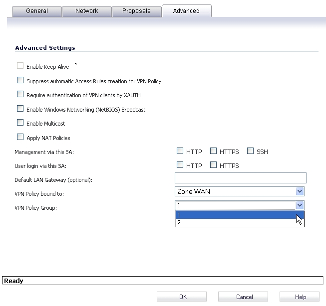
VPN policy configuration requires association with a Virtual Group when running in Active/Active Clustering mode. In the VPN Policy window, both the Network and Advanced tabs have new configuration options for creating this association.
On the Network tab, Virtual Group address objects are available for the Choose local network from list option. These Virtual Group address objects are created by SonicOS when virtual IP addresses are added, and are deleted when the virtual IP is deleted.
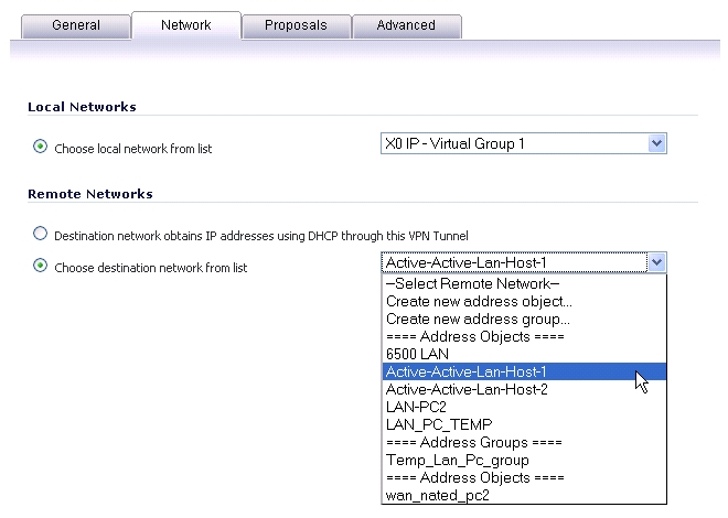
If creating a VPN Policy for a remote network, Virtual Group address objects may also be available. For example, this graphic shows one with the custom name Active-Active-Lan-Host-1.
On the Advanced tab, you can select the Virtual Group number for the VPN Policy Group setting. The default is Virtual Group 1.
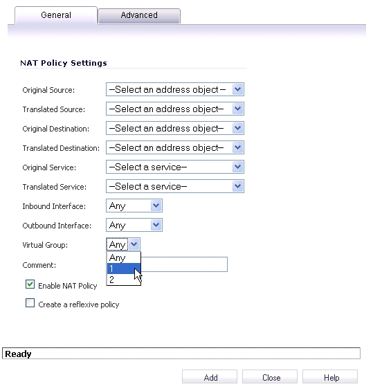
When running in Active/Active Clustering mode, NAT policy configuration includes Virtual Group settings. Default NAT policies are created by SonicOS when virtual IP addresses are added, and are deleted when the virtual IP is deleted. You can specify a Virtual Group or select Any when creating custom NAT policies. This graphic shows the NAT policy automatically created for Virtual Group 2 on interface X1.
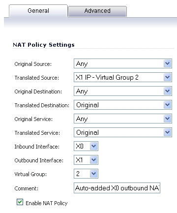
This graphic shows the selections for the Virtual Group option in the Add NAT Policy window when creating a custom NAT policy.