Network_netInterfaces
Network > Interfaces
The Network > Interfaces page includes interface objects that are directly linked to physical interfaces. The SonicOS Enhanced scheme of interface addressing works in conjunction with network zones and address objects. The interfaces displayed on the Network > Interfaces page depend on the type of SonicWALL appliance. The page pictured below is for SonicWALL TZ 100 or 200 Wireless-N appliances.
This chapter contains the following sections:
Setup Wizard
The Setup Wizard button accesses the Setup Wizard . The Setup Wizard walks you through the configuration of the SonicWALL security appliance for Internet connectivity. For Setup Wizard instructions, see “ Wizards > Setup Wizard ” .
Interface Settings
The Interface Settings table lists the following information for each interface:
|
|
|
Name - listed as X0 through X8 and W0 , depending on your SonicWALL security appliance model. |
|
|
|
The X0 and X1 gigabit interfaces are for LAN and WAN, respectively. On the TZ 210 Series, X0 and X1 are the only gigabit interfaces. X2 is the only gigabit interface for the NSA 240. |
|
|
|
Zone - LAN, DMZ, WAN, and WLAN are listed by default. As zones are configured, the names are listed in this column. |
|
|
|
IP Address - IP address assigned to the interface. |
|
|
|
Subnet Mask - the network mask assigned to the subnet. |
|
|
|
IP Assignment - the main page displays one of the following types of IP assignments, based on the zone type of the interfaces: |
|
|
|
Non-WAN : Static, Transparent, or Layer 2 Bridged Mode. |
|
|
|
WAN : Static, DHCP, PPPoE, PPTP, or L2TP. |
|
|
|
Status - the link status and speed. |
|
|
|
Comment - any user-defined comments. |
|
|
|
Configure
- click the Configure
icon |
Interface Traffic Statistics
The Interface Traffic Statistics table lists received and transmitted information for all configured interfaces.
The following information is displayed for all SonicWALL security appliance interfaces:
|
|
|
Rx Unicast Packets - indicates the number of point-to-point communications received by the interface. |
|
|
|
Rx Broadcast Packets - indicates the number of multipoint communications received by the interface. |
|
|
|
RX Bytes - indicates the volume of data, in bytes, received by the interface. |
|
|
|
Tx Unicast Packets - indicates the number of point-to-point communications transmitted by the interface. |
|
|
|
Tx Broadcast Bytes - indicates the number of mutlipoint communications transmitted by the interface. |
|
|
|
Tx Bytes - indicates the volume of data, in bytes, transmitted by the interface. |
To clear the current statistics, click the Clear Statistics button at the top right of the Network > Interfaces page.
Physical and Virtual Interfaces
|
|
|
Physical interfaces – Physical interfaces are bound to a single port |
|
|
|
Virtual interfaces – Virtual interfaces are assigned as subinterfaces to a physical interface and allow the physical interface to carry traffic assigned to multiple interfaces. |
|
|
|
PortShield interfaces – PortShield interfaces are a feature of the SonicWALL TZ series and SonicWALL NSA 240. Any number of the LAN ports on these appliances can be combined into a single PortShield interface. |
Physical Interfaces
Physical interfaces must be assigned to a zone to allow for configuration of Access Rules to govern inbound and outbound traffic. Security zones are bound to each physical interface where it acts as a conduit for inbound and outbound traffic. If there is no interface, traffic cannot access the zone or exit the zone.
For more information on zones, see “ Network > Zones ” .
Virtual Interfaces (VLAN)
Supported on SonicWALL NSA series security appliances, virtual Interfaces are subinterfaces assigned to a physical interface. Virtual interfaces allow you to have more than one interface on one physical connection.
Virtual interfaces provide many of the same features as physical interfaces, including zone assignment, DHCP Server, and NAT and Access Rule controls.
Virtual Local Area Networks (VLANs) can be described as a ‘tag-based LAN multiplexing technology’ because through the use of IP header tagging, VLANs can simulate multiple LAN’s within a single physical LAN. Just as two physically distinct, disconnected LAN’s are wholly separate from one another, so too are two different VLANs, however the two VLANs can exist on the very same wire. VLANs require VLAN aware networking devices to offer this kind of virtualization – switches, routers and firewalls that have the ability to recognize, process, remove and insert VLAN tags in accordance with the network’s design and security policies.
VLANs are useful for a number of different reasons, most of which are predicated on the VLANs ability to provide logical rather than physical broadcast domain, or LAN boundaries. This works both to segment larger physical LAN’s into smaller virtual LAN’s, as well as to bring physically disparate LAN’s together into a logically contiguous virtual LAN. The benefits of this include:
|
|
|
Increased performance – Creating smaller, logically partitioned broadcast domains decreases overall network utilization, sending broadcasts only where they need to be sent, thus leaving more available bandwidth for application traffic. |
|
|
|
Decreased costs – Historically, broadcast segmentation was performed with routers, requiring additional hardware and configuration. With VLANs, the functional role of the router is reversed – rather than being used for the purposes of inhibiting communications, it is used to facilitate communications between separate VLANs as needed. |
|
|
|
Virtual workgroups – Workgroups are logical units that commonly share information, such as a Marketing department or an Engineering department. For reasons of efficiency, broadcast domain boundaries should be created such that they align with these functional workgroups, but that is not always possible: Engineering and Marketing users might be commingled, sharing the same floor (and the same workgroup switch) in a building, or just the opposite – the Engineering team might be spread across an entire campus. Attempting to solve this with complex feats of wiring can be expensive and impossible to maintain with constant adds and moves. VLANs allow for switches to be quickly reconfigured so that logical network alignment can remain consistent with workgroup requirements. |
|
|
|
Security – Hosts on one VLAN cannot communicate with hosts on another VLAN unless some networking device facilitates communication between them. |
Subinterfaces
VLAN support on SonicOS Enhanced is achieved by means of subinterfaces, which are logical interfaces nested beneath a physical interface. Every unique VLAN ID requires its own subinterface. For reasons of security and control, SonicOS does not participate in any VLAN trunking protocols, but instead requires that each VLAN that is to be supported be configured and assigned appropriate security characteristics.
|
|
|
Dynamic VLAN Trunking protocols, such as VTP (VLAN Trunking Protocol) or GVRP (Generic VLAN Registration Protocol), should not be used on trunk links from other devices connected to the SonicWALL. |
Trunk links from VLAN capable switches are supported by declaring the relevant VLAN ID’s as a subinterface on the SonicWALL, and configuring them in much the same way that a physical interface would be configured. In other words, only those VLANs which are defined as subinterfaces will be handled by the SonicWALL, the rest will be discarded as uninteresting. This method also allows the parent physical interface on the SonicWALL to which a trunk link is connected to operate as a conventional interface, providing support for any native (untagged) VLAN traffic that might also exist on the same link. Alternatively, the parent interface may remain in an ‘unassigned’ state.
VLAN subinterfaces have most of the capabilities and characteristics of a physical interface, including zone assignability, security services, GroupVPN, DHCP server, IP Helper, routing, and full NAT policy and Access Rule controls. Features excluded from VLAN subinterfaces at this time are WAN dynamic client support and multicast support. The following table lists the maximum number of subinterfaces supported on each platform.
|
Number of Subinterfaces
Supported
|
|
SonicOS Enhanced Secure Objects
The SonicOS Enhanced scheme of interface addressing works in conjunction with network zones and address objects. This structure is based on secure objects, which are utilized by rules and policies within SonicOS Enhanced.
Secured objects include interface objects that are directly linked to physical interfaces and managed in the Network > Interfaces page. Address objects are defined in the Network > Address Objects page. Service and Scheduling objects are defined in the Firewall section of the SonicWALL security appliance Management Interface, and User objects are defined in the Users section of the SonicWALL security appliance Management Interface.
Zones are the hierarchical apex of SonicOS Enhanced’s secure objects architecture. SonicOS Enhanced includes predefined zones as well as allow you to define your own zones. Predefined zones include LAN, DMZ, WAN, WLAN, and Custom. Zones can include multiple interfaces, however, the WAN zone is restricted to a total of two interfaces. Within the WAN zone, either one or both WAN interfaces can be actively passing traffic depending on the WAN Failover and Load Balancing configuration on the Network > WAN Failover & LB page.
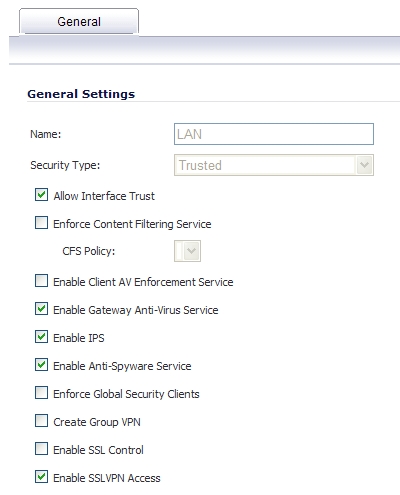
For more information on WAN Failover and Load Balancing on the SonicWALL security appliance, see “Network > Failover & Load Balancing” .
At the zone configuration level, the Allow Interface Trust setting for zones automates the processes involved in creating a permissive intra-zone Access Rule. It creates a comprehensive Address Object for the entire zone and a inclusively permissive Access Rule from zone address to zone addresses.
Transparent Mode
Transparent Mode in SonicOS Enhanced uses interfaces as the top level of the management hierarchy. Transparent Mode supports unique addressing and interface routing.
Layer 2 Bridge Mode
SonicOS Enhanced firmware versions 4.0 and higher includes L2 (Layer 2) Bridge Mode , a new method of unobtrusively integrating a SonicWALL security appliance into any Ethernet network. L2 Bridge Mode is ostensibly similar to SonicOS Enhanced’s Transparent Mode in that it enables a SonicWALL security appliance to share a common subnet across two interfaces, and to perform stateful and deep-packet inspection on all traversing IP traffic, but it is functionally more versatile.
In particular, L2 Bridge Mode employs a secure learning bridge architecture, enabling it to pass and inspect traffic types that cannot be handled by many other methods of transparent security appliance integration. Using L2 Bridge Mode, a SonicWALL security appliance can be non-disruptively added to any Ethernet network to provide in-line deep-packet inspection for all traversing IPv4 TCP and UDP traffic. In this scenario the SonicWALL UTM appliance is not used for security enforcement, but instead for bidirectional scanning, blocking viruses and spyware, and stopping intrusion attempts.
Unlike other transparent solutions, L2 Bridge Mode can pass all traffic types, including IEEE 802.1Q VLANs (on SonicWALL NSA appliances), Spanning Tree Protocol, multicast, broadcast, and IPv6, ensuring that all network communications will continue uninterrupted.
Another aspect of the versatility of L2 Bridge Mode is that you can use it to configure IPS Sniffer Mode . Supported on SonicWALL NSA series appliances, IPS Sniffer Mode uses a single interface of a Bridge-Pair to monitor network traffic from a mirrored port on a switch. IPS Sniffer Mode provides intrusion detection, but cannot block malicious traffic because the SonicWALL security appliance is not connected inline with the traffic flow. For more information about IPS Sniffer Mode, see “IPS Sniffer Mode” .
L2 Bridge Mode provides an ideal solution for networks that already have an existing firewall, and do not have immediate plans to replace their existing firewall but wish to add the security of SonicWALL Unified Threat Management (UTM) deep-packet inspection, such as Intrusion Prevention Services, Gateway Anti Virus, and Gateway Anti Spyware. If you do not have SonicWALL UTM security services subscriptions, you may sign up for free trials from the Security Service > Summary page of your SonicWALL.
You can also use L2 Bridge Mode in a High Availability deployment. This scenario is explained in the “Layer 2 Bridge Mode with High Availability” section .
Key Features of SonicOS Enhanced Layer 2 Bridge Mode
The following table outlines the benefits of each key feature of layer 2 bridge mode:
|
L2 Bridging with Deep Packet Inspection |
This method of transparent operation means that a SonicWALL security appliance can be added to any network without the need for readdressing or reconfiguration, enabling the addition of deep-packet inspection security services with no disruption to existing network designs. Developed with connectivity in mind as much as security, L2 Bridge Mode can pass all Ethernet frame types, ensuring seamless integration. |
|
True L2 behavior means that all allowed traffic flows natively through the L2 Bridge. Whereas other methods of transparent operation rely on ARP and route manipulation to achieve transparency, which frequently proves problematic, L2 Bridge Mode dynamically learns the topology of the network to determine optimal traffic paths. |
|
|
Universal Ethernet Frame-Type Support |
All Ethernet traffic can be passed across an L2 Bridge, meaning that all network communications will continue uninterrupted. While many other methods of transparent operation will only support IPv4 traffic, L2 Bridge Mode will inspect all IPv4 traffic, and will pass (or block, if desired) all other traffic, including LLC, all Ethertypes, and even proprietary frame formats. |
|
L2 Bridge Mode can concurrently provide L2 Bridging and conventional security appliance services, such as routing, NAT, VPN, and wireless operations. This means it can be used as an L2 Bridge for one segment of the network, while providing a complete set of security services to the remainder of the network. This also allows for the introduction of the SonicWALL security appliance as a pure L2 bridge, with a smooth migration path to full security services operation. |
|
|
Use a single IP subnet across multiple zone types, including LAN, WLAN, DMZ, or custom zones. This feature allows wireless and wired clients to seamlessly share the same network resources, including DHCP addresses.The Layer 2 protocol can run between paired interfaces, allowing multiple traffic types to traverse the bridge, including broadcast and non-ip packets. |
Key Concepts to Configuring L2 Bridge Mode and Transparent Mode
The following terms will be used when referring to the operation and configuration of L2 Bridge Mode:
|
|
|
L2 Bridge Mode – A method of configuring SonicWALL security appliance, which enables the SonicWALL to be inserted inline into an existing network with absolute transparency, beyond even that provided by Transparent Mode. Layer 2 Bridge Mode also refers to the IP Assignment configuration that is selected for Secondary Bridge Interfaces that are placed into a Bridge-Pair . |
|
|
|
Transparent Mode – A method of configuring a SonicWALL security appliance that allows the SonicWALL to be inserted into an existing network without the need for IP reconfiguration by spanning a single IP subnet across two or more interfaces through the use of automatically applied ARP and routing logic. |
|
|
|
IP Assignment – When configuring a Trusted (LAN) or Public (DMZ) interface, the IP Assignment for the interface can either be: |
|
|
|
Static – The IP address for the interface is manually entered. |
|
|
|
Transparent Mode – The IP address(es) for the interface is assigned using an Address Object (Host, Range, or Group) that falls within the WAN Primary IP subnet, effectively spanning the subnet from the WAN interface to the assigned interface. |
|
|
|
Layer 2 Bridge Mode – An interface placed in this mode becomes the Secondary Bridge Interface to the Primary Bridge Interface to which it is paired. The resulting Bridge-Pair will then behave like a two-port learning bridge with full L2 transparency, and all IP traffic that passes through will be subjected to full stateful failover and deep packet inspection. |
|
|
|
Bridge-Pair – The logical interface set composed of a Primary Bridge Interface and a Secondary Bridge Interface . The terms primary and secondary do not imply any inherent level of operational dominance or subordination; both interfaces continue to be treated according to their zone type, and to pass IP traffic according to their configured Access Rules. Non-IPv4 traffic across the Bridge-Pair is controlled by the Block all non-IPv4 traffic setting on the Secondary Bridge Interface . A system may support as many Bridge Pairs as it has interface pairs available. In other words, the maximum number of Bridge-Pairs is equal to ½ the number of physical interfaces on the platform. Membership in a Bridge-Pair does not preclude an interface from conventional behavior; for example, if X1 is configured as a Primary Bridge Interface paired to X3 as a Secondary Bridge Interface , X1 can simultaneously operate in its traditional role as the Primary WAN, performing NAT for Internet-bound traffic through the Auto-added X1 Default NAT Policy . |
|
|
|
Primary Bridge Interface – A designation that is assigned to an interface once a Secondary Bridge Interface has been paired to it. A Primary Bridge Interface can belong to an Untrusted (WAN), Trusted (LAN), or Public (DMZ) zone. |
|
|
|
Secondary Bridge Interface – A designation that is assigned to an interface whose IP Assignment has been configured for Layer 2 Bridge Mode . A Secondary Bridge Interface can belong to a Trusted (LAN), or Public (DMZ) zone. |
|
|
|
Bridge Management Address – The address of the Primary Bridge Interface is shared by both interfaces of the Bridge-Pair . If the Primary Bridge Interface also happens to be the Primary WAN interface, it is this address that is uses for outbound communications by the SonicWALL, such as NTP, and License Manager updates. Hosts that are connected to either segment of the Bridge-Pair may also use the Bridge Management Address as their gateway, as will be common in Mixed-Mode deployments. |
|
|
|
Bridge-Partner – The term used to refer to the ‘other’ member of a Bridge-Pair . |
|
|
|
Non-IPv4 Traffic - SonicOS Enhanced supports the following IP protocol types: ICMP (1), IGMP (2), TCP (6), UDP (17), GRE (47), ESP (50), AH (51), EIGRP (88), OSPF (89), PIM-SM (103), L2TP (115). More esoteric IP types, such as Combat Radio Transport Protocol (126), are not natively handled by the SonicWALL, nor are non-IPv4 traffic types such as IPX or (currently) IPv6. L2 Bridge Mode can be configured to either pass or drop Non-IPv4 traffic. |
|
|
|
Captive-Bridge Mode – This optional mode of L2 Bridge operation prevents traffic that has entered an L2 bridge from being forwarded to a non-Bridge-Pair interface. By default, L2 Bridge logic will forward traffic that has entered the L2 Bridge to its destination along the most optimal path as determined by ARP and routing tables. In some cases, the most optimal path might involve routing or NATing to a non-Bridge-Pair interface. Activating Captive-Bridge mode ensures that traffic which enters an L2 Bridge exits the L2 Bridge rather than taking its most logically optimal path. In general, this mode of operation is only required in complex networks with redundant paths, where strict path adherence is required. |
|
|
|
Pure L2 Bridge Topology – Refers to deployments where the SonicWALL will be used strictly in L2 Bridge Mode for the purposes of providing in-line security to a network. This means that all traffic entering one side of the Bridge-Pair will be bound for the other side, and will not be routed/NATed through a different interface. This will be common in cases where there is an existing perimeter security appliance, or where in-line security is desired along some path (for example, inter-departmentally, or on a trunked link between two switches) of an existing network. Pure L2 Bridge Topology is not a functional limitation, but rather a topological description of a common deployment in heterogeneous environments. |
|
|
|
Mixed-Mode Topology – Refers to deployments where the Bridge-Pair will not will not be the only point of ingress/egress through the SonicWALL. This means that traffic entering one side of the Bridge-Pair may be destined to be routed/NATed through a different interface. This will be common when the SonicWALL is simultaneously used to provide security to one or more Bridge-Pair while also providing: |
|
|
|
Firewall and Security services to additional segments, such as Trusted (LAN) or Public (DMZ) interface, where communications will occur between hosts on those segments and hosts on the Bridge-Pair. |
|
|
|
Wireless services with SonicPoints, where communications will occur between wireless clients and hosts on the Bridge-Pair. |
Comparing L2 Bridge Mode to Transparent Mode
This comparison of L2 Bridge Mode to Transparent Mode contains the following sections:
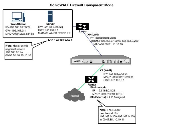
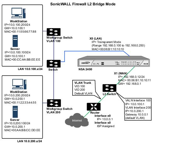
While Transparent Mode allows a security appliance running SonicOS Enhanced to be introduced into an existing network without the need for re-addressing, it presents a certain level of disruptiveness, particularly with regard to ARP, VLAN support, multiple subnets, and non-IPv4 traffic types. Consider the diagram below, in a scenario where a Transparent Mode SonicWALL appliance has just been added to the network with a goal of minimally disruptive integration, particularly:
|
|
|
No need reconfigure or otherwise modify the gateway router (as is common when the router is owned by the ISP) |
ARP in Transparent Mode
ARP – Address Resolution Protocol (the mechanism by which unique hardware addresses on network interface cards are associated to IP addresses) is proxied in Transparent Mode. If the Workstation on Server on the left had previously resolved the Router (192.168.0.1) to its MAC address 00:99:10:10:10:10, this cached ARP entry would have to be cleared before these hosts could communicate through the SonicWALL. This is because the SonicWALL proxies (or answers on behalf of) the gateway’s IP (192.168.0.1) for hosts connected to interfaces operating in Transparent Mode. So when the Workstation at the left attempts to resolve 192.168.0.1, the ARP request it sends is responded to by the SonicWALL with its own X0 MAC address (00:06:B1:10:10:10).
The SonicWALL also proxy ARPs the IP addresses specified in the Transparent Range (192.168.0.100 to 192.168.0.250) assigned to an interface in Transparent Mode for ARP requests received on the X1 (Primary WAN) interface. If the Router had previously resolved the Server (192.168.0.100) to its MAC address 00:AA:BB:CC:DD:EE, this cached ARP entry would have to be cleared before the router could communicate with the host through the SonicWALL. This typically requires a flushing of the router’s ARP cache either from its management interface or through a reboot. Once the router’s ARP cache is cleared, it can then send a new ARP request for 192.168.0.100, to which the SonicWALL will respond with its X1 MAC 00:06:B1:10:10:11.
VLAN Support in Transparent Mode
While the network depicted in the above diagram is simple, it is not uncommon for larger networks to use VLANs for segmentation of traffic. If this was such a network, where the link between the switch and the router was a VLAN trunk, a Transparent Mode SonicWALL would have been able to terminate the VLANs to subinterfaces on either side of the link, but it would have required unique addressing; that is, non-Transparent Mode operation requiring re-addressing on at least one side. This is because only the Primary WAN interface can be used as the source for Transparent Mode address space.
Multiple Subnets in Transparent Mode
It is also common for larger networks to employ multiple subnets, be they on a single wire,
on separate VLANs, multiple wires, or some combination. While Transparent Mode is capable of supporting multiple subnets through the use of Static ARP and Route entries, as the Technote
http://www.sonicwall.com/us/support/2134_3468.html
describes, it is not an effortless process.
Non-IPv4 Traffic in Transparent Mode
Transparent Mode will drop (and generally log) all non-IPv4 traffic, precluding it from passing other traffic types, such as IPX, or unhandled IP types.
L2 Bridge Mode addresses these common Transparent Mode deployment issues and is described in the following section.
Simple Transparent Mode Topology
ARP in L2 Bridge Mode
L2 Bridge Mode employs a learning bridge design where it will dynamically determine which hosts are on which interface of an L2 Bridge (referred to as a Bridge-Pair). ARP is passed through natively, meaning that a host communicating across an L2 Bridge will see the actual host MAC addresses of their peers. For example, the Workstation communicating with the Router (192.168.0.1) will see the router as 00:99:10:10:10:10, and the Router will see the Workstation (192.168.0.100) as 00:AA:BB:CC:DD:EE.
This behavior allows for a SonicWALL operating in L2 Bridge Mode to be introduced into an existing network with no disruption to most network communications other than that caused by the momentary discontinuity of the physical insertion.
Please note that stream-based TCP protocols communications (for example, an FTP session between a client and a server) will need to be re-established upon the insertion of an L2 Bridge Mode SonicWALL. This is by design so as to maintain the security afforded by stateful packet inspection (SPI); since the SPI engine can not have knowledge of the TCP connections which pre-existed it, it will drop these established packets with a log event such as TCP packet received on non-existent/closed connection; TCP packet dropped .
VLAN Support in L2 Bridge Mode
On SonicWALL NSA series appliances, L2 Bridge Mode provides fine control over 802.1Q VLAN traffic traversing an L2 Bridge. The default handling of VLANs is to allow and preserve all 802.1Q VLAN tags as they pass through an L2 Bridge, while still applying all firewall rules, and stateful and deep-packet inspection to the encapsulated traffic. It is further possible to specify white/black lists for allowed/disallowed VLAN IDs through the L2 Bridge.
This allows a SonicWALL operating in L2 Bridge Mode to be inserted, for example, inline into a VLAN trunk carrying any number of VLANs, and to provide full security services to all IPv4 traffic traversing the VLAN without the need for explicit configuration of any of the VLAN IDs or subnets. Firewall Access Rules can also, optionally, be applied to all VLAN traffic passing through the L2 Bridge Mode because of the method of handling VLAN traffic.
L2 Bridge IP Packet Path
![]()
The following sequence of events describes the above flow diagram:
|
|
802.1Q encapsulated frame enters an L2 Bridge interface (this first step, the next step, and the final step apply only to 802.1Q VLAN traffic, supported on SonicWALL NSA series appliances). |
|
|
|
If the VLAN ID is allowed, the packet is de-capsulated, the VLAN ID is stored, and the inner packet (including the IP header) is passed through the full packet handler. |
|
|
Since any number of subnets is supported by L2 Bridging, no source IP spoof checking is performed on the source IP of the packet. It is possible to configure L2 Bridges to only support a certain subnet or subnets using Firewall Access Rules. |
|
|
A destination route lookup is performed to the destination zone, so that the appropriate Firewall Access rule can be applied. Any zone is a valid destination, including the same zone as the source zone (e.g. LAN to LAN), the Untrusted zone (WAN), the Encrypted (VPN), Wireless (WLAN), Multicast, or custom zones of any type. |
|
|
|
In general, the destination for packets entering an L2 Bridge will be the Bridge-Partner interface (that is, the other side of the bridge). In these cases, no translation will be performed. |
|
|
|
In cases where the L2 Bridge Management Address is the gateway, as will sometimes be the case in Mixed-Mode topologies , then NAT will be applied as need (see the L2 Bridge Path Determination section for more details). |
|
|
Firewall Access Rules are applied to the packet. For example, on SonicWALL NSA series appliances, the following packet decode shows an ICMP packet bearing VLAN ID 10, source IP address 110.110.110.110 destined for IP address 4.2.2.1. |
![]()
It is possible to construct a Firewall Access Rule to control any IP packet , independent of its VLAN membership, by any of its IP elements, such as source IP, destination IP, or service type. If the packet is disallowed, it will be dropped and logged. If the packet is allowed, it will continue.
|
|
A connection cache entry is made for the packet, and required NAT translations (if any) are performed. |
|
|
Stateful packet inspection and transformations are performed for TCP, VoIP, FTP, MSN, Oracle, RTSP and other media streams, PPTP and L2TP. If the packet is disallowed, it will be dropped and logged. If the packet is allowed, it will continue. |
|
|
Deep packet inspection, including GAV, IPS, Anti-Spyware, CFS and email-filtering is performed. If the packet is disallowed, it will be dropped and logged. If the packet is allowed, it will continue. Client notification will be performed as configured. |
|
|
If the packet is destined for the Encrypted zone (VPN), the Untrusted zone (WAN), or some other connected interface (the last two of which might be the case in Mixed-Mode Topologies) the packet will be sent via the appropriate path. |
|
|
If the packet is not destined for the VPN/WAN/Connected interface, the stored VLAN tag will be restored, and the packet (again bearing the original VLAN tag) will be sent out the Bridge-Partner interface. |
Multiple Subnets in L2 Bridge Mode
L2 Bridge Mode is capable of handling any number of subnets across the bridge, as described above. The default behavior is to allow all subnets, but Access Rules can be applied to control traffic as needed.
Non-IPv4 Traffic in L2 Bridge Mode
Unsupported traffic will, by default, be passed from one L2 Bridge interface to the Bridge- Partner interface. This allows the SonicWALL to pass other traffic types, including LLC packets such as Spanning Tree, other EtherTypes, such as MPLS label switched packets (EtherType 0x8847), Appletalk (EtherType 0x809b), and the ever-popular Banyan Vines (EtherType 0xbad). These non-IPv4 packets will only be passed across the Bridge, they will not be inspected or controlled by the packet handler. If these traffic types are not needed or desired, the bridging behavior can be changed by enabling the Block all non-IPv4 traffic option on the Secondary Bridge Interface configuration page.
Comparison of L2 Bridge Mode to Transparent Mode
|
ARP (Address Resolution Protocol) information is unaltered. MAC addresses natively traverse the L2 bridge. Packets that are destined for SonicWALL’s MAC addresses will be processed, others will be passed, and the source and destinations will be learned and cached. |
ARP is proxied by the interfaces operating in Transparent Mode. |
|
|
Hosts on either side of a Bridge-Pair are dynamically learned. There is no need to declare interface affinities. |
The Primary WAN interface is always the master ingress/egress point for Transparent mode traffic, and for subnet space determination. Hosts transparently sharing this subnet space must be explicitly declared through the use of Address Object assignments. |
|
|
Two interfaces, a Primary Bridge Interface and a Secondary Bridge Interface. |
Two or more interfaces. The master interface is always the Primary WAN. There can be as many transparent subordinate interfaces as there are interfaces available. |
|
|
The maximum number of Bridge-Pairs allowed is limited only by available physical interfaces. This can be described as “many One-to-One pairings”. |
Transparent Mode only allows the Primary WAN subnet to be spanned to other interfaces, although it allows for multiple interfaces to simultaneously operate as transparent partners to the Primary WAN. This can be described as “a single One-to-One” or “a single One-to-Many pairing”. |
|
|
The Primary Bridge Interface can be Untrusted, Trusted, or Public. The Secondary Bridge Interface can be Trusted or Public. |
Interfaces in a Transparent Mode pair must consist of one Untrusted interface (the Primary WAN, as the master of the pair’s subnet) and one or more Trusted/Public interface (e.g. LAN or DMZ). |
|
|
Any number of subnets is supported. Firewall Access Rules can be written to control traffic to/from any of the subnets as needed. |
In its default configuration, Transparent Mode only supports a single subnet (that which is assigned to, and spanned from the Primary WAN). It is possible to manually add support for additional subnets through the use of ARP entries and routes. |
|
|
All non-IPv4 traffic, by default, is bridged from one Bridge-Pair interface to the Bridge-Partner interface, unless disabled on the Secondary Bridge Interface configuration page. This includes IPv6 traffic, STP (Spanning Tree Protocol), and unrecognized IP types. |
Non IPv4 traffic is not handled by Transparent Mode, and is dropped and logged. |
|
|
VLAN traffic is passed through the L2 Bridge, and is fully inspected by the Stateful and Deep Packet Inspection engines. |
VLAN subinterfaces can be created and can be given Transparent Mode Address Object assignments, but the VLANs will be terminated by the SonicWALL rather than passed. |
|
|
VLAN subinterfaces can be configured on Bridge-Pair interfaces, but they will be passed through the bridge to the Bridge-Partner unless the destination IP address in the VLAN frame matches the IP address of the VLAN subinterface on the SonicWALL, in which case it will be processed (e.g. as management traffic). |
VLAN subinterfaces can be assigned to physical interfaces operating in Transparent Mode, but their mode of operation will be independent of their parent. These VLAN subinterfaces can also be given Transparent Mode Address Object assignments, but in any event VLAN subinterfaces will be terminated rather than passed. |
|
|
PortShield interfaces cannot be assigned to either interface of an L2 Bridge Pair. |
PortShield interfaces may be assigned a Transparent Mode range. |
|
|
Although a Primary Bridge Interface may be assigned to the WAN zone, only static addressing is allowable for Primary Bridge Interfaces. |
Although Transparent Mode employs the Primary WAN as a master interface, only static addressing is allowable for Transparent Mode. |
|
|
VPN operation is supported with one additional route configured. See the “VPN Integration with Layer 2 Bridge Mode” section for details. |
VPN operation is supported with no special configuration requirements. |
|
|
Interfaces operating in Transparent Mode can provide DHCP services, or they can pass DHCP using IP Helper. |
||
|
Traffic will be intelligently routed in/out of the L2 Bridge-Pair from/to other paths. By default, traffic will not be NATed from one Bridge-Pair interface to the Bridge-Partner, but it can be NATed to other paths, as needed. Custom routes and NAT policies can be added as needed. |
Traffic will be intelligently routed from/to other paths. By default, traffic will not be NATed from/to the WAN to/from Transparent Mode interface, but it can be NATed to other paths, as needed. Custom routes and NAT policies can be added as needed. |
|
|
Stateful Packet Inspection |
Full stateful packet inspection will be applied to all IPv4 traffic traversing the L2 Bridge for all subnets, including VLAN traffic on SonicWALL NSA series appliances. |
Full stateful packet inspection will applied to traffic from/to the subnets defined by Transparent Mode Address Object assignment. |
|
All security services (GAV, IPS, Anti-Spy, CFS) are fully supported. All regular IP traffic, as well as all 802.1Q encapsulated VLAN traffic. |
All security services (GAV, IPS, Anti-Spy, CFS) are fully supported from/to the subnets defined by Transparent Mode Address Object assignment. |
|
|
Broadcast traffic is passed from the receiving Bridge-Pair interface to the Bridge-Partner interface. |
Broadcast traffic is dropped and logged, with the possible exception of NetBIOS which can be handled by IP Helper. |
|
|
Multicast traffic is inspected and passed across L2 Bridge-Pairs providing Multicast has been activated on the Firewall > Multicast page. It is not dependent upon IGMP messaging, nor is it necessary to enable multicast support on the individual interfaces. |
Multicast traffic, with IGMP dependency, is inspected and passed by Transparent Mode providing Multicast has been activated on the Firewall > Multicast page, and multicast support has been enabled on the relevant interfaces. |
Benefits of Transparent Mode over L2 Bridge Mode
The following are circumstances in which Transparent Mode might be preferable over L2 Bridge Mode :
|
|
|
Two interfaces are the maximum allowed in an L2 Bridge Pair. If more than two interfaces are required to operate on the same subnet, Transparent Mode should be considered. |
|
|
|
PortShield interface may not operate within an L2 Bridge Pair. If PortShield interfaces are required to operate on the same subnet, Transparent Mode should be considered. |
|
|
|
VLAN subinterfaces, supported on SonicWALL NSA series appliances, may not operate within an L2 Bridge Pair. If VLAN subinterfaces are required to operate on the same subnet, Transparent Mode should be considered. It is, however, possible to configure a VLAN subinterface on an interface that is part of a Bridge-Pair; the subinterface will simply operate independently on the Bridge-Pair in every respect. |
Comparing L2 Bridge Mode to the CSM Appliance
L2 Bridge Mode is more similar in function to the CSM than it is to Transparent Mode, but it differs from the current CSM behavior in that it handles VLANs and non-IPv4 traffic types, which the CSM does not. Future versions of the SonicOS CF Software for the CSM will likely adopt the more versatile traffic handling capabilities of L2 Bridge Mode.
L2 Bridge Path Determination
Packets received by the SonicWALL on Bridge-Pair interfaces must be forwarded along to the appropriate and optimal path toward their destination, whether that path is the Bridge-Partner, some other physical or sub interface, or a VPN tunnel. Similarly, packets arriving from other paths (physical, virtual or VPN) bound for a host on a Bridge-Pair must be sent out over the correct Bridge-Pair interface. The following summary describes, in order, the logic that is applied to path determinations for these cases:
|
|
If present, the most specific non-default route to the destination is chosen. This would cover, for example: |
|
|
A packet arriving on X3 (non-L2 Bridge LAN) destined for host 15.1.1.100 subnet, where a route to the 15.1.1.0/24 subnet exists through 192.168.0.254 via the X0 (Secondary Bridge Interface, LAN) interface. The packet would be forwarded via X0 to the destination MAC address of 192.168.0.254, with the destination IP address 15.1.1.100. |
|
|
A packet arriving on X4 (Primary Bridge Interface, LAN) destined for host 10.0.1.100, where a route to the 10.0.1.0/24 exists through 192.168.10.50 via the X5 (DMZ) interface. The packet would be forwarded via X5 to the destination MAC address of 192.168.10.50, with the destination IP address 10.0.1.100. |
|
|
If no specific route to the destination exists, an ARP cache lookup is performed for the destination IP address. A match will indicate the appropriate destination interface. This would cover, for example: |
|
|
A packet arriving on X3 (non-L2 Bridge LAN) destined for host 192.168.0.100 (residing on L2 Primary Bridge Interface X2). The packet would be forwarded via X2 to the known destination MAC and IP address of 192.168.0.100, as derived from the ARP cache. |
|
|
A packet arriving on X4 (Primary Bridge Interface, LAN) destined for host 10.0.1.10 (residing on X5 – DMZ). The packet would be forwarded via X5 to the known destination MAC and IP address of 10.0.1.10, as derived from the ARP cache. |
|
|
If the packet arrives from some other path, the SonicWALL will send an ARP request out both interfaces of the Bridge-Pair to determine on which segment the destination IP resides. |
In this last case, since the destination is unknown until after an ARP response is received, the destination zone also remains unknown until that time. This precludes the SonicWALL from being able to apply the appropriate Access Rule until after path determination is completed. Upon completion, the correct Access Rule will be applied to subsequent related traffic.
With regard to address translation (NAT) of traffic arriving on an L2 Bridge-Pair interface:
|
|
If it is determined to be bound for the Bridge-Partner interface, no IP translation (NAT) will be performed. |
|
|
If the path is another connected (local) interface, there will likely be no translation. That is, it will effectively be routed as a result of hitting the last-resort Any->Original NAT Policy. |
|
|
IIf the path is determined to be via the WAN, then the default Auto -added [interface] outbound NAT Policy for X1 WAN will apply, and the packet’s source will be translated for delivery to the Internet. This is common in the case of Mixed-Mode topologies, such as that depicted in the “Internal Security” section ). |
L2 Bridge Interface Zone Selection
Bridge-Pair interface zone assignment should be done according to your network’s traffic flow requirements. Unlike Transparent Mode, which imposes a system of “more trusted to less trusted” by requiring that the source interface be the Primary WAN, and the transparent interface be Trusted or Public, L2 Bridge mode allows for greater control of operational levels of trust. Specifically, L2 Bridge Mode allows for the Primary and Secondary Bridge Interfaces to be assigned to the same or different zones (e.g. LAN+LAN, LAN+DMZ, WAN+CustomLAN, etc.) This will affect not only the default Access Rules that are applied to the traffic, but also the manner in which Deep Packet Inspection security services are applied to the traffic traversing the bridge. Important areas to consider when choosing and configuring interfaces to use in a Bridge-Pair are Security Services, Access Rules, and WAN connectivity:
Security Services Directionality
As it will be one of the primary employments of L2 Bridge mode, understanding the application of security services is important to the proper zone selection for Bridge-Pair interfaces. Security services applicability is based on the following criteria:
|
|
|
GAV is primarily an Inbound service, inspecting inbound HTTP, FTP, IMAP, SMTP, POP3, and TCP Streams. It also has an additional Outbound element for SMTP. |
|
|
|
Anti Spyware is primarily Inbound, inspecting inbound HTTP, FTP, IMAP, SMTP, POP3 for the delivery (i.e. retrieval) of Spyware components as generally recognized by their class IDs. It also has an additional Outbound component, where Outbound is used relative to the directionality (namely, Outgoing) ascribed to it by the IPS signatures that trigger the recognition of these Spyware components. The Outgoing classifier (described in the table below) is used because these components are generally retrieved by the client (e.g. LAN host) via HTTP from a Web-server on the Internet (WAN host). Referring to the table below, that would be an Outgoing connection, and requires a signature with an Outgoing directional classification. |
|
|
|
IPS has three directions: Incoming, Outgoing, and Bidirectional. Incoming and Outgoing are described in the table below, and Bidirectional refers to all points of intersection on the table. |
|
|
|
For additional accuracy, other elements are also considered, such as the state of the connection (e.g. SYN or Established), and the source of the packet relative to the flow (i.e. initiator or responder). |
|
|
The direction of the traffic . The direction of the traffic as it pertains to IPS is primarily determined by the Source and Destination zone of the traffic flow. When a packet is received by the SonicWALL, its source zone is generally immediately known, and its destination zone is quickly determined by doing a route (or VPN) lookup. |
Based on the source and destination, the packet’s directionality is categorized as either Incoming or Outgoing, (not to be confused with Inbound and Outbound) where the following criteria is used to make the determination:
Table data is subject to change.
In addition to this categorization, packets traveling to/from zones with levels of additional trust, which are inherently afforded heightened levels of security (LAN|Wireless|Encrypted<-->LAN|Wireless|Encrypted) are given the special Trust classification. Traffic with the Trust classification has all signatures applied (Incoming, Outgoing, and Bidirectional).
|
|
The direction of the signature . This pertains primarily to IPS, where each signature is assigned a direction by SonicWALL’s signature development team. This is done as an optimization to minimize false positives. Signature directions are: |
|
|
|
Incoming – Applies to Incoming and Trust . The majority of signatures are Incoming, and they include all forms of application exploits and all enumeration and footprinting attempts. Approximately 85% of signatures are Incoming. |
|
|
|
Outgoing – Applies to Outgoing and Trust . Examples of Outgoing signatures would include IM and P2P login attempts, and responses to successfully launched exploits (e.g. Attack Responses). Approximately 10% of signatures are Outgoing. |
|
|
|
Bidirectional – Applies to all. Examples of Bidirectional signatures would include IM file transfers, various NetBIOS attacks (e.g. Sasser communications) and a variety of DoS attacks (e.g. UDP/TCP traffic destined to port 0). Approximately 5% of signatures are Bidirectional. |
|
|
Zone application . For a signature to be triggered, the desired security service must be active on at least one of the zones it traverses . For example, a host on the Internet (X1, WAN) accessing a Microsoft Terminal Server (on X3, Secondary Bridge Interface, LAN) will trigger the Incoming signature “IPS Detection Alert: MISC MS Terminal server request, SID: 436, Priority: Low” if IPS is active on the WAN , the LAN , or both. |
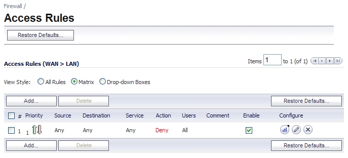
Access Rule Defaults
Default, zone-to-zone Access Rules. The default Access Rules should be considered, although they can be modified as needed. The defaults are as follows:
![]()
WAN Connectivity
Internet (WAN) connectivity is required for stack communications, such as licensing, security services signature downloads, NTP (time synchronization), and CFS (Content Filtering Services). At present, these communications can only occur through the Primary WAN interface. If you require these types of communication, the Primary WAN should have a path to the Internet. Whether or not the Primary WAN is employed as part of a Bridge-Pair will not affect its ability to provide these stack communications (for example on a PRO 4100, X0+X2 and X3+X4 could be used to create two Bridge-Pairs separate of X1).
|
|
|
If Internet connectivity is not available, licensing can be performed manually and signature updates can also be performed manually (http://www.sonicwall.com/us/support/2134_4170.html ). |
Sample Topologies
The following are sample topologies depicting common deployments. Inline Layer 2 Bridge Mode represents the addition of a SonicWALL security appliance to provide UTM services in a network where an existing firewall is in place. Perimeter Security represents the addition of a SonicWALL security appliance in pure L2 Bridge mode to an existing network, where the SonicWALL is placed near the perimeter of the network. Internal Security represents the full integration of a SonicWALL security appliance in mixed-mode , where it provides simultaneous L2 bridging, WLAN services, and NATed WAN access. Layer 2 Bridge Mode with High Availability represents the mixed-mode scenario where the SonicWALL HA pair provide high availability along with L2 bridging. Layer 2 Bridge Mode with SSL VPN represents the scenario where a SonicWALL Aventail SSL VPN or SonicWALL SSL VPN Series appliance is deployed in conjunction with L2 Bridge mode.
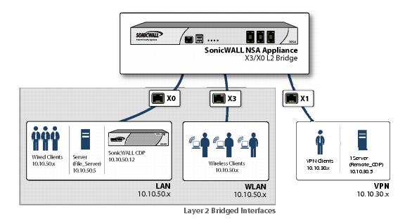
Wireless Layer 2 Bridge
In wireless mode, after bridging the wireless (WLAN) interface to a LAN or DMZ zone, the WLAN zone becomes the secondary bridged interface, allowing wireless clients to share the same subnet and DHCP pool as their wired counterparts
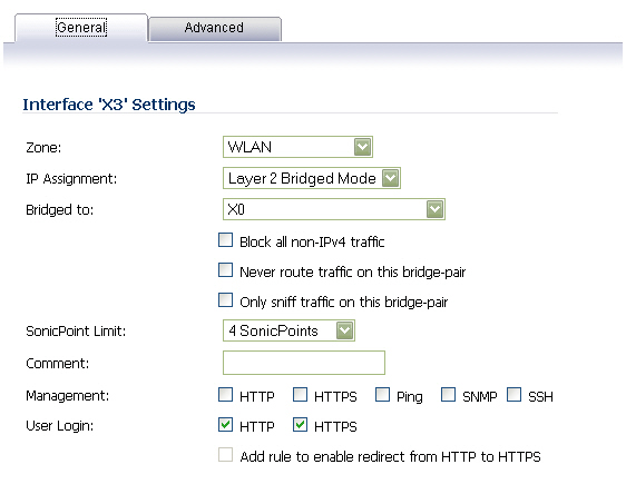
To configure a WLAN to LAN Layer 2 interface bridge:
|
|
Navigate to the Network > Interfaces page in the SonicOS management interface. |
|
|
Click the Configure icon for the wireless interface you wish to bridge. The Edit Interface window displays. |
|
|
Select Layer 2 Bridged Mode as the IP Assignment . |
|
|
|
Although a general rule is automatically created to allow traffic between the WLAN zone and your choosen bridged interface, WLAN zone type security properties still apply. Any specific rules must be manually added. |
|
|
Select the Interface which the WLAN should be Bridged To . In this instance, the X0 (default LAN zone) is chosen. |
|
|
Configure the remaining options normally. For more information on configuring WLAN interfaces, see the “Configuring Wireless Interfaces” section . |
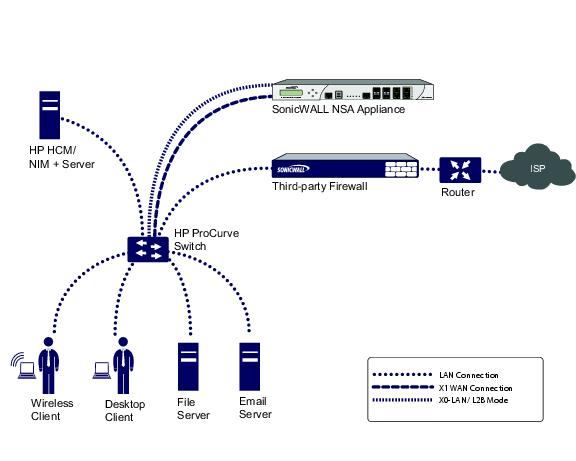
Inline Layer 2 Bridge Mode
This method is useful in networks where there is an existing firewall that will remain in place, but you wish to utilize the SonicWALL’s UTM services without making major changes to the network. By placing the SonicWALL in Layer 2 Bridge mode, the X0 and X1 interfaces become part of the same broadcast domain/network (that of the X1 WAN interface).
This example refers to a SonicWALL UTM appliance installed in a Hewlitt Packard ProCurve switching environment. SonicWALL is a member of HP’s ProCurve Alliance – more details can be found at the following location: http://www.procurve.com/alliance/members/sonicwall.htm .
HP’s ProCurve Manager Plus (PCM+) and HP Network Immunity Manager (NIM) server software packages can be used to manage the switches as well as some aspects of the SonicWALL UTM appliance.
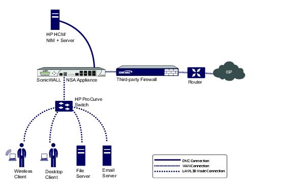
To configure the SonicWALL appliance for this scenario, navigate to the Network > Interfaces page and click on the configure icon for the X0 LAN interface. On the X0 Settings page, set the IP Assignment to ‘Layer 2 Bridged Mode’ and set the Bridged To: interface to ‘X1’. Also make sure that the interface is configured for HTTP and SNMP so it can be managed from the DMZ by PCM+/NIM. Click OK to save and activate the change.
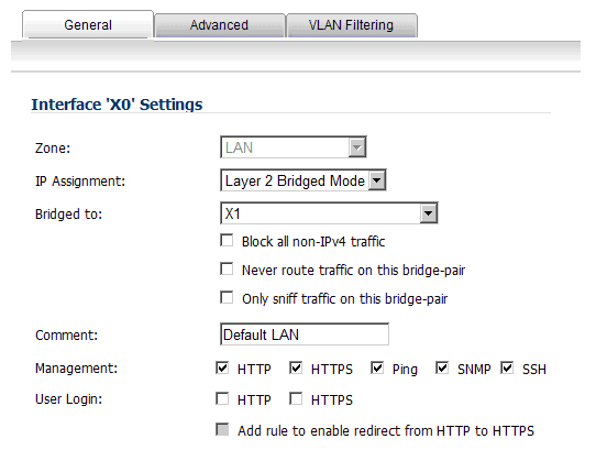
You will also need to make sure to modify the firewall access rules to allow traffic from the LAN to WAN, and from the WAN to the LAN, otherwise traffic will not pass successfully. You may also need to modify routing information on your firewall if your PCM+/NIM server is placed on the DMZ.
Perimeter Security
The following diagram depicts a network where the SonicWALL is added to the perimeter for the purpose of providing security services (the network may or may not have an existing firewall between the SonicWALL and the router).
In this scenario, everything below the SonicWALL (the Primary Bridge Interface segment) will generally be considered as having a lower level of trust than everything to the left of the SonicWALL (the Secondary Bridge Interface segment). For that reason, it would be appropriate to use X1 (Primary WAN) as the Primary Bridge Interface .
Traffic from hosts connected to the Secondary Bridge Interface (LAN) would be permitted outbound through the SonicWALL to their gateways (VLAN interfaces on the L3 switch and then through the router), while traffic from the Primary Bridge Interface (WAN) would, by default, not be permitted inbound.
If there were public servers, for example, a mail and Web server, on the Secondary Bridge Interface (LAN) segment, an Access Rule allowing WAN->LAN traffic for the appropriate IP addresses and services could be added to allow inbound traffic to those servers.
Internal Security
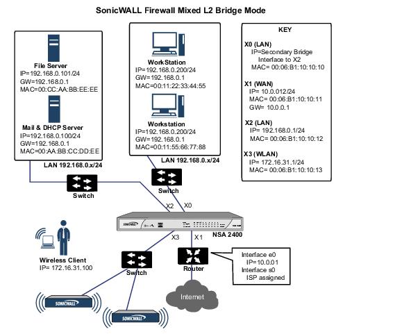
This diagram depicts a network where the SonicWALL will act as the perimeter security device and secure wireless platform. Simultaneously, it will provide L2 Bridge security between the workstation and server segments of the network without having to readdress any of the workstation or servers .
This typical inter-departmental Mixed Mode topology deployment demonstrates how the SonicWALL can simultaneously Bridge and route/NAT. Traffic to/from the Primary Bridge Interface (Server) segment from/to the Secondary Bridge Interface (Workstation) segment will pass through the L2 Bridge.
Since both interfaces of the Bridge-Pair are assigned to a Trusted (LAN) zone, the following will apply:
Consider, for the point of contrast, what would occur if the X2 (Primary Bridge Interface) was instead assigned to a Public (DMZ) zone: All the Workstations would be able to reach the Servers, but the Servers would not be able to initiate communications to the Workstations. While this would probably support the traffic flow requirements (i.e. Workstations initiating sessions to Servers), it would have two undesirable effects:
|
|
The DHCP server would be in the DMZ. DHCP requests from the Workstations would pass through the L2 Bridge to the DHCP server (192.168.0.100), but the DHCP offers from the server would be dropped by the default DMZ->LAN Deny Access Rule. An Access Rule would have to be added, or the default modified, to allow this traffic from the DMZ to the LAN. |
|
|
Security services directionality would be classified as Outgoing for traffic from the Workstations to the Server since the traffic would have a Trusted source zone and a Public destination zone. This might be sub-optimal since it would provide less scrutiny than the Incoming or (ideally) Trust classifications. |
|
|
|
Security services directionality would be classified as Trust , and all signatures (Incoming , Outgoing , and Bidirectional ) will be applied, providing the highest level of security to/from both segments. |
For detailed instructions on configuring interfaces in Layer 2 Bridge Mode, see “Configuring Layer 2 Bridge Mode”
Layer 2 Bridge Mode with High Availability
This method is appropriate in networks where both High Availability and Layer 2 Bridge Mode are desired. This example is for SonicWALL NSA series appliances, and assumes the use of switches with VLANs configured.
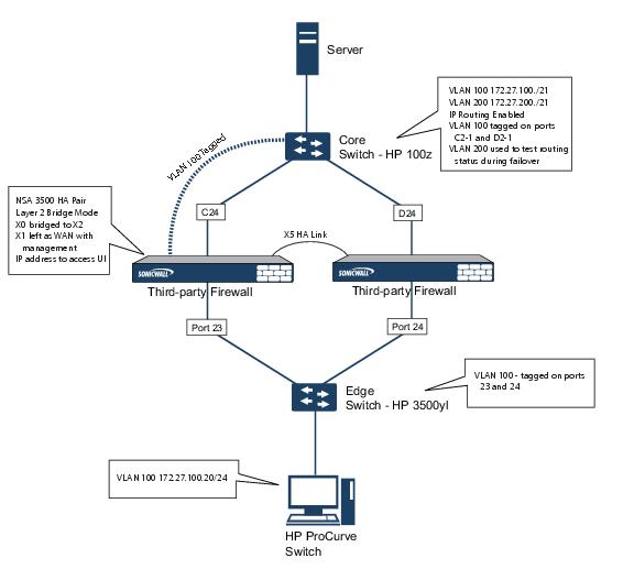
The SonicWALL HA pair consists of two SonicWALL NSA 3500 appliances, connected together on port X5, the designated HA port. Port X1 on each appliance is configured for normal WAN connectivity and is used for access to the management interface of that device. Layer 2 Bridge Mode is implemented with port X0 bridged to port X2.
When setting up this scenario, there are several things to take note of on both the SonicWALLs and the switches.
|
|
|
Do not enable the Virtual MAC option when configuring High Availability. In a Layer 2 Bridge Mode configuration, this function is not useful. |
|
|
|
Enabling Preempt Mode is not recommended in an inline environment such as this. If Preempt Mode is required, follow the recommendations in the documentation for your switches, as the trigger and failover time values play a key role here. |
|
|
|
Consider reserving an interface for the management network (this example uses X1). If it is necessary to assign IP addresses to the bridge interfaces for probe purposes or other reasons, SonicWALL recommends using the management VLAN network assigned to the switches for security and administrative purposes. Note that the IP addresses assigned for HA purposes do not directly interact with the actual traffic flow. |
|
|
|
Using multiple tag ports: As shown in the above diagram, two tag (802.1q) ports were created for VLAN 100 on both the Edge switch (ports 23 and 24) and Core switch (C24 - D24). The NSA 3500 appliances are connected inline between these two switches. In a high performance environment, it is usually recommended to have Link Aggregation/ Port Trunking, Dynamic LACP, or even a completely separate link designated for such a deployment (using OSPF), and the fault tolerance of each of the switches must be considered. Consult your switch documentation for more information. |
|
|
|
On HP ProCurve switches, when two ports are tagged in the same VLAN, the port group will automatically be placed into a failover configuration. In this case, as soon as one port fails, the other one becomes active. |
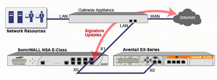
Layer 2 Bridge Mode with SSL VPN
This sample topology covers the proper installation of a SonicWALL UTM device into your existing SonicWALL EX-Series SSL VPN or SonicWALL SSL VPN networking environment. By placing the UTM appliance into Layer 2 Bridge Mode, with an internal, private connection to the SSL VPN appliance, you can scan for viruses, spyware, and intrusions in both directions. In this scenario the SonicWALL UTM appliance is not used for security enforcement, but instead for bidirectional scanning, blocking viruses and spyware, and stopping intrusion attempts. When programmed correctly, the UTM appliance will not interrupt network traffic, unless the behavior or content of the traffic is determined to be undesirable. Both one- and two-port deployments of the SonicWALL UTM appliance are covered in this section.
WAN to LAN Access Rules
Because the UTM appliance will be used in this deployment scenario only as an enforcement point for anti-virus, anti-spyware and intrusion prevention, its existing security policy must be modified to allow traffic to pass in both directions between the WAN and LAN.
On the Firewall > Access Rules page, click the Configure icon for the intersection of WAN to LAN traffic. Click the Configure icon next to the default rule that implicitly blocks uninitiated traffic from the WAN to the LAN.
In the Edit Rule window, select Allow for the Action setting, and then click OK .
Configure the Network Interfaces and Activate L2B Mode
In this scenario the WAN interface is used for the following:
|
|
|
The default route for the device and subsequently the “next hop” for the internal traffic of the SSL VPN appliance (this is why the UTM device WAN interface must be on the same IP segment as the internal interface of the SSL VPN appliance) |
The LAN interface on the UTM appliance is used to monitor the unencrypted client traffic coming from the external interface of the SSL VPN appliance. This is the reason for running in Layer 2 Bridge Mode (instead of reconfiguring the external interface of the SSL VPN appliance to see the LAN interface as the default route).
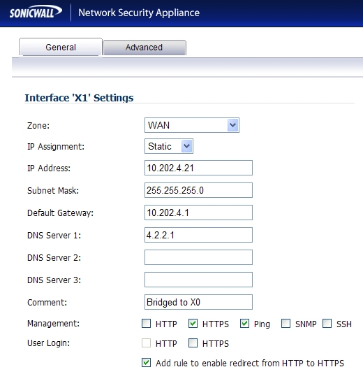
On the Network > Interfaces page of the SonicOS Enhanced management interface, click the Configure icon for the WAN interface, and then assign it an address that can access the Internet so that the appliance can obtain signature updates and communicate with NTP.
The gateway and internal/external DNS address settings will match those of your SSL VPN appliance:
|
|
|
IP address : This must match the address for the internal interface on the SSL VPN appliance. |
|
|
|
Subnet Mask , Default Gateway , and DNS Server(s) : Make these addresses match your SSL VPN appliance settings. |
For the Management setting, select the HTTPS and Ping check boxes. Click OK to save and activate the changes.
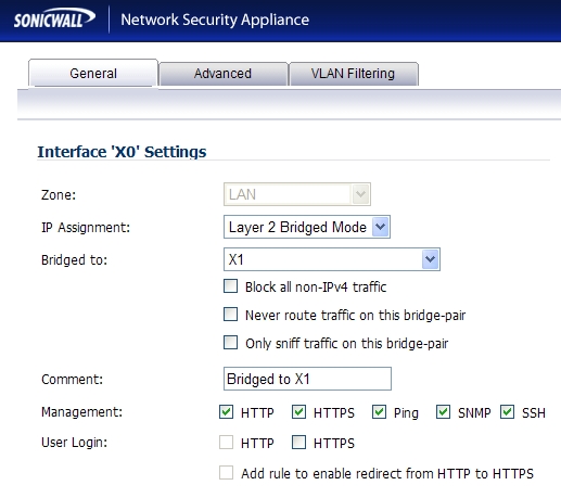
To configure the LAN interface settings, navigate to the Network > Interfaces page and click the Configure icon for the LAN interface.
For the IP Assignment setting, select Layer 2 Bridged Mode . For the Bridged to setting, select X1 .
If you also need to pass VLAN tagged traffic, supported on SonicWALL NSA series appliances, click the VLAN Filtering tab and add all of the VLANs that will need to be passed.
Click OK to save and activate the change. You may be automatically disconnected from the UTM appliance’s management interface. You can now disconnect your management laptop or desktop from the UTM appliance’s X0 interface and power the UTM appliance off before physically connecting it to your network.
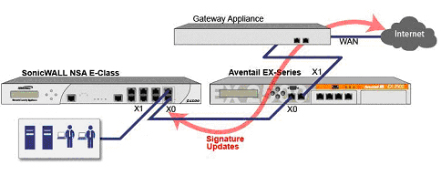
Install the SonicWALL UTM appliance between the network and SSL VPN appliance
Regardless of your deployment method (single- or dual-homed), the SonicWALL UTM appliance should be placed between the X0/LAN interface of the SSL VPN appliance and the connection to your internal network. This allows the device to connect out to SonicWALL’s licensing and signature update servers, and to scan the decrypted traffic from external clients requesting access to internal network resources.
If your SSL VPN appliance is in two-port mode behind a third-party firewall, it is dual-homed. To connect a dual-homed SSL VPN appliance, follow these steps:
|
|
Cable the X1/WAN port on the UTM appliance to the port where the SSL VPN was previously connected. |
|
|
Power on the UTM appliance. |
If your SSL VPN appliance is in one-port mode in the DMZ of a third-party firewall, it is single- homed. To connect a single-homed SSL VPN appliance, follow these steps:
|
|
Cable the X1/WAN port on the UTM appliance to the port where the SSL VPN was previously connected. |
|
|
Power on the UTM appliance. |
Configure or verify settings
From a management station inside your network, you should now be able to access the management interface on the UTM appliance using its WAN IP address.
Make sure that all security services for the SonicWALL UTM appliance are enabled. See “Licensing Services” and “Activating UTM Services on Each Zone” .
SonicWALL Content Filtering Service must be disabled before the device is deployed in conjunction with a SonicWALL Aventail SSL VPN appliance. On the Network > Zones page, click Configure next to the LAN (X0) zone, clear the Enforce Content Filtering Service check box and then click OK .
If you have not yet changed the administrative password on the SonicWALL UTM appliance, you can do so on the System > Administration page.
To test access to your network from an external client, connect to the SSL VPN appliance and log in. Once connected, attempt to access to your internal network resources. If there are any problems, review your configuration and see the “Configuring the Common Settings for L2 Bridge Mode Deployments” section .
IPS Sniffer Mode
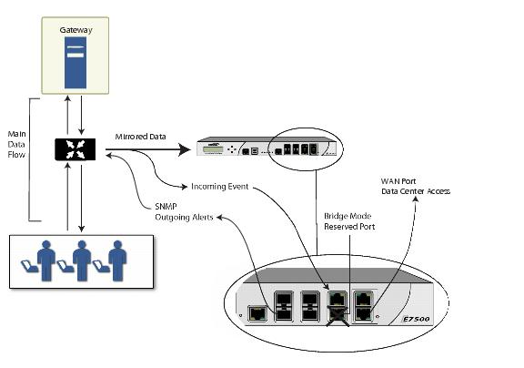
Supported on SonicWALL NSA series appliances, IPS Sniffer Mode is a variation of Layer 2 Bridge Mode that is used for intrusion detection. IPS Sniffer Mode configuration allows an interface on the SonicWALL to be connected to a mirrored port on a switch to examine network traffic. Typically, this configuration is used with a switch inside the main gateway to monitor traffic on the intranet.
In the network diagram below, traffic flows into a switch in the local network and is mirrored through a switch mirror port into a IPS Sniffer Mode interface on the SonicWALL security appliance. The SonicWALL inspects the packets according to the Unified Threat Management (UTM) settings configured on the Bridge-Pair. Alerts can trigger SNMP traps which are sent to the specified SNMP manager via another interface on the SonicWALL. The network traffic is discarded after the SonicWALL inspects it.
The WAN interface of the SonicWALL is used to connect to the SonicWALL Data Center for signature updates or other data.
In IPS Sniffer Mode, a Layer 2 Bridge is configured between two interfaces in the same zone on the SonicWALL, such as LAN-LAN or DMZ-DMZ. You can also create a custom zone to use for the Layer 2 Bridge. Only the WAN zone is not appropriate for IPS Sniffer Mode.
The reason for this is that SonicOS detects all signatures on traffic within the same zone such as LAN-LAN traffic, but some directional specific (client-side versus server-side) signatures do not apply to some LAN-WAN cases.
Either interface of the Layer 2 Bridge can be connected to the mirrored port on the switch. As network traffic traverses the switch, the traffic is also sent to the mirrored port and from there into the SonicWALL for deep packet inspection. Malicious events trigger alerts and log entries, and if SNMP is enabled, SNMP traps are sent to the configured IP address of the SNMP manager system. The traffic does not actually continue to the other interface of the Layer 2 Bridge. IPS Sniffer Mode does not place the SonicWALL appliance inline with the network traffic, it only provides a way to inspect the traffic.
The Edit Interfaces screen available from the Network > Interfaces page provides a new checkbox called Only sniff traffic on this bridge-pair for use when configuring IPS Sniffer Mode. When selected, this checkbox causes the SonicWALL to inspect all packets that arrive on the L2 Bridge from the mirrored switch port. The Never route traffic on this bridge-pair checkbox should also be selected for IPS Sniffer Mode to ensure that the traffic from the mirrored switch port is not sent back out onto the network.
For detailed instructions on configuring interfaces in IPS Sniffer Mode, see “Configuring IPS Sniffer Mode” .
Sample IPS Sniffer Mode Topology
This section provides an example topology that uses SonicWALL IPS Sniffer Mode in a Hewlitt Packard ProCurve switching environment. This scenario relies on the ability of HP’s ProCurve Manager Plus (PCM+) and HP Network Immunity Manager (NIM) server software packages to throttle or close ports from which threats are emanating.
This method is useful in networks where there is an existing firewall that will remain in place, but you wish to use the SonicWALL’s UTM services as a sensor.
In this deployment the WAN interface and zone are configured for the internal network’s addressing scheme and attached to the internal network. The X2 port is Layer 2 bridged to the LAN port – but it won’t be attached to anything. The X0 LAN port is configured to a second, specially programmed port on the HP ProCurve switch. This special port is set for mirror mode – it will forward all the internal user and server ports to the “sniff” port on the SonicWALL. This allows the SonicWALL to analyze the entire internal network’s traffic, and if any traffic triggers the UTM signatures it will immediately trap out to the PCM+/NIM server via the X1 WAN interface, which then can take action on the specific port from which the threat is emanating.
To configure this deployment, navigate to the Network > Interfaces page and click on the configure icon for the X2 interface. On the X2 Settings page, set the IP Assignment to ‘Layer 2 Bridged Mode’ and set the Bridged To: interface to ‘X0’. Select the checkbox for Only sniff traffic on the bridge-pair . Click OK to save and activate the change.
Next, go to the Network > Interfaces page and click on the configure icon for the X1 WAN interface. On the X1 Settings page, assign it a unique IP address for the internal LAN segment of your network – this may sound wrong, but this will actually be the interface from which you manage the appliance, and it is also the interface from which the appliance sends its SNMP traps as well as the interface from which it gets UTM signature updates. Click OK .
You must also modify the firewall rules to allow traffic from the LAN to WAN, and from the WAN to the LAN, otherwise traffic will not pass successfully.
Connect the span/mirror switch port to X0 on the SonicWALL, not to X2 (in fact X2 isn’t plugged in at all), and connect X1 to the internal network. Use care when programming the ports that are spanned/mirrored to X0.