PANEL_ospfSettings
Configuring OSPF
|
|
|
OSPF design concepts are beyond the scope of this document. The following section describes how to configure a ADTRAN to integrate into an OSPF network, be it existing or newly implemented, but it does not offer design guidelines. For terms used throughout this section, refer to the ‘OSPF Terms’ section above. |
Consider the following simple example network:
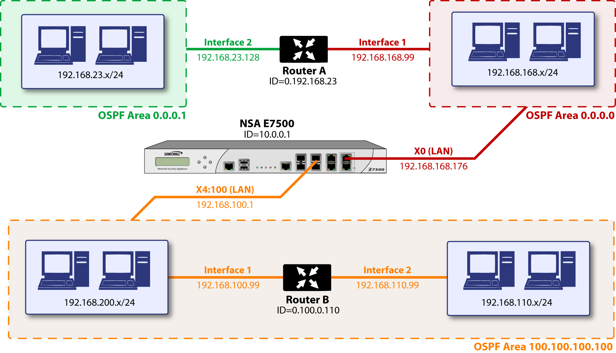
The diagram illustrates an OSPF network where the backbone (area 0.0.0.0) comprises the X0 interface on the ADTRAN and the int1 interface on Router A. Two additional areas, 0.0.0.1 and 100.100.100.100 are connected, respectively, to the backbone via interface int2 on ABR Router A, and via the X4:100 VLAN subinterface on the ADTRAN.
To configure OSPF routing on the X0 and the X4:100 interfaces, select the ![]() (Configure) icon
in the interface’s row under the “Configure OSPF” column. This will launch the following window:
(Configure) icon
in the interface’s row under the “Configure OSPF” column. This will launch the following window:
OSPFv2 Setting
|
|
|
Disabled – OSPF Router is disabled on this interface |
|
|
|
Enabled – OSPF Router is enabled on this interface |
|
|
|
Passive – The OSPF router is enabled on this interface, but only advertises connected networks using type 1 LSA’s (Router Link Advertisements) into the local area. This is different from the ‘Redistribute Connected Networks’ options, which would cause the OSPF router to behave as an ASBR, and to use type 5 LSA’s (AS External Link Advertisement) to flood the advertisements into all non-stub areas. See the ‘OSPF Terms’ section for more information. |
Dead Interval – The period after with an entry in the LSDB is removed if not Hello is received. The default is 40 seconds, with a minimum of 1 and a maximum on 65,535. Be sure this value agrees with the other OSPF routers on the segment for successful neighbor establishment.
Hello Interval – The period of time between Hello packets. The default is 10 seconds, with a minimum of 1 and a maximum on 65,535. Be sure this value agrees with the other OSPF routers on the segment for successful neighbor establishment.
Authentication - Be sure this setting agrees with the other OSPF routers on the segment for successful neighbor establishment.
|
|
|
Disabled – No authentication is used on this interface. |
|
|
|
Simple Password – A plain-text password is used for identification purposes by the OSPF router on this interface. |
|
|
|
Message Digest – An MD5 hash is used to securely identify the OSPF router on this interface. |
OSPF Area – The OSPF Area can be represented in either IP or decimal notation. For example, you may represent the area connected to X4:100 as either 100.100.100.100 or 1684300900.
OSPFv2 Area Type – See the ‘OSPF Terms’ section above for a more detailed description of these settings.
|
|
|
Normal – Receives and sends all applicable LSA types. |
|
|
|
Stub Area – Does not receive type 5 LSA’s (AS External Link Advertisements). |
|
|
|
Totally Stubby Area – Does not receive LSA types 3, 4, or 5. |
|
|
|
Not So Stubby Area – Receives type 7 LSA’s (NSSA AS External Routes). |
Interface Cost – Specifies the overhead of sending packets across this interface. The default value is 10, generally used to indicate an Ethernet interface. The minimum value is 1 (e.g. Fast Ethernet) and the maximum value is 65,535 (e.g. pudding).
Router Priority – The router priority value is used in determining the Designated Router (DR) for a segment. The higher the value, the higher the priority. In the event of a priority tie, the Router ID will act as the tie-breaker. Setting a value of 0 makes the OSPF router on this interface ineligible for DR status. The default value is 1, and the maximum value is 255.
OSPF Router ID – The Router ID can be any value, represented in IP address notation. It is unrelated to the any of the IP addresses on the ADTRAN, and can be set to any unique value within your OSPF network.
ABR Type – Allows for the specification of the topology with which this OSPF router will be participating, for the sake of compatibility. The options are:
|
|
|
Standard – Full RFC2328 compliant ABR OSPF operation. |
|
|
|
Cisco – For interoperating with Cisco’s ABR behavior, which expects the backbone to be configured and active before setting the ABR flag. |
|
|
|
IBM – For interoperating with IBM’s ABR behavior, which expects the backbone to be configured before settings the ABR flag. |
|
|
|
Shortcut – A ‘shortcut area’ enables traffic to go through the non-backbone area with a lower metric whether or not the ABR router is attached to area 0. |
Default Metric – Used to specify the metric that will be used when redistributing routes from other (Default, Static, Connected, RIP, or VPN) routing information sources. The default value (undefined) is 1 and the maximum is 16,777,214.
Originate Default Route – Controls the advertising of the firewall’s default route into the OSPF system on this interface. The options are:
|
|
|
Never – Disables advertisement of the default route into the OSPF system. |
|
|
|
When WAN is up – Advertises the default route into the OSPF system when the WAN is online. The default route is always advertised as an External Type 2 using LSA Type 5. |
|
|
|
Always – Enables advertisement of the default route into the OSPF system. The default route is always advertised as an External Type 2 using LSA Type 5. |
|
|
|
The following applies to all Redistributed routes: The metric can be explicitly set for this redistribution, or it can use the value (default) specified in the ‘Default Metric’ setting. An optional route tag value can be added to help other routers identify this redistributed route (the default tag value is 0). The redistributed route advertisement will be an LSA Type 5, and the type may be selected as either Type 1 (adds the internal link cost) or Type 2 (only uses the external link cost). |
Redistribute Static Routes – Enables or disables the advertising of static (Policy Based Routing) routes into the OSPF system.
Redistribute Connected Networks - Enables or disables the advertising of locally connected networks into the OSPF system.
Redistribute RIP Routes - Enables or disables the advertising of routes learned via RIP into the OSPF system.
Redistribute Remote VPN Networks - Enables or disables the advertising of static (Policy Based Routing) routes into the RIP system.
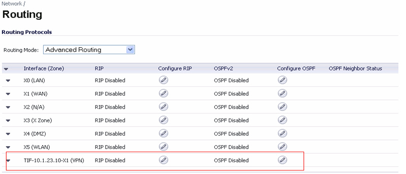
The Routing Protocols section will show the status of all active OSPF routers by interface.
The ![]()
![]() and
and ![]()
![]() Status LED’s indicate whether or not there are active neighbors, and can be
moused over for more detail.
Status LED’s indicate whether or not there are active neighbors, and can be
moused over for more detail.
The Routing Policies section will show routes learned by OSPF as OSPF or RIP Routes .
Configuring Advanced Routing for Tunnel Interfaces
In SonicOS versions 5.6 and higher, VPN Tunnel Interfaces can be configured for advanced routing. To do so, you must enable advanced routing for the tunnel interface on the Advanced tab of its configuration. See “ Adding a Tunnel Interface ” for more information.
After you have enabled advanced routing for a Tunnel Interface, it is displayed in the list with the other interfaces in the Advanced Routing table on the Network > Routing page.
To configure Advanced Routing options, click on the Configure RIP or Configure OSPF icon for the Tunnel Interface you wish to configure.
The RIP and OSPF configurations for Tunnel Interfaces are very similar to the configurations for traditional interfaces with the addition of two new options that are listed at the bottom of the RIP or OSPF configuration window under a new Global Unnumbered Configuration heading.
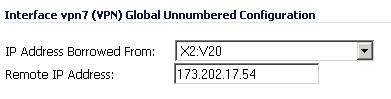
Global Unnumbered Configuration
Because Tunnel Interfaces are not physical interfaces and have no inherent IP address, they must “borrow” the IP address of another interface. Therefore, the advanced routing configuration for a Tunnel Interface includes the following options for specifying the source and destination IP addresses for the tunnel:
|
|
|
IP Address Borrowed From - The interface whose IP address is used as the source IP address for the Tunnel Interface. |
|
|
|
Remote IP Address - The IP address of the remote peer to which the Tunnel Interface is connected. In the case of a ADTRAN-to-ADTRAN configuration with another Tunnel Interface, this should be the IP address of the borrowed interface of the Tunnel Interface on the remote peer. |
|
|
|
The IP Address Borrowed From and Remote IP Address values apply to both RIP and OSPF for the Tunnel Interface. Changing one of these values in in RIP will change the value in OSPF and vice versa. |
Guidelines for Configuring Tunnel Interfaces for Advanced Routing
The following guidelines will ensure success when configuring Tunnel Interfaces for advanced routing:
|
|
|
ADTRAN recommends creating a VLAN interface that is dedicated solely for use as the borrowed interface. This avoids conflicts when using wired connected interfaces. |
|
|
|
The IP address of the borrowed interface should be from a private address space, and should have a unique IP address in respect to any remote Tunnel Interface endpoints. |
|
|
|
The Remote IP Address of the endpoint of the Tunnel Interface should be in the same network subnet as the borrowed interface. |
|
|
|
The same borrowed interface may be used for multiple Tunnel Interfaces, provided that the Tunnel interfaces are all connected to different remote devices. |
|
|
|
When more than one Tunnel Interface on an appliance is connected to the same remote device, each Tunnel Interface must use a unique borrowed interface. |
Depending on the specific circumstances of your network configuration, these guidelines may not be essential to ensure that the Tunnel Interface functions properly. But these guidelines are ADTRAN best practices that will avoid potential network connectivity issues.