PANEL_editInterface
Configuring Interfaces
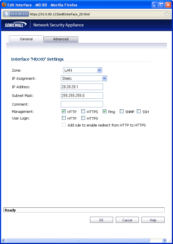
Configuring the Static Interfaces
For general information on interfaces, see Network > Interfaces .
Static means that you assign a fixed IP address to the interface.
|
|
Click on the
Configure
icon |
|
|
|
You can configure X0 through X8 , depending on the number of interfaces on your appliance. |
|
|
|
If you want to create a new zone, select Create new zone . The Add Zone window is displayed. See “Network > Zones” for instructions on adding a zone. |
|
|
Select a zone to assign to the interface. You can select LAN, WAN, DMZ, WLAN, or a custom zone. |
|
|
Select Static from the IP Assignment menu. |
|
|
Enter the IP address and subnet mask of the zone in the IP Address and Subnet Mask fields. |
|
|
Enter any optional comment text in the Comment field. This text is displayed in the Comment column of the Interface table. |
|
|
If you want to enable remote management of the SonicWALL security appliance from this interface, select the supported management protocol(s): HTTP , HTTPS , SSH , Ping , SNMP , and/or SSH . |
To allow access to the WAN interface for management from another zone on the same appliance, access rules must be created. See “Allowing WAN Primary IP Access from the LAN Zone” for more information.
|
|
If you want to allow selected users with limited management rights to log in to the security appliance, select HTTP and/or HTTPS in User Login . |
|
|
Click OK . |
|
|
|
The administrator password is required to regenerate encryption keys after changing the SonicWALL security appliance’s address. |
Configuring Advanced Settings for the Interface
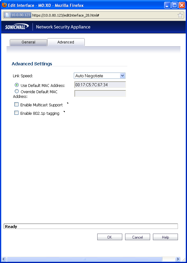
If you need to force an Ethernet speed, duplex and/or MAC address, click the Advanced tab.
The Ethernet Settings section allows you to manage the Ethernet settings of links connected to the SonicWALL. Auto Negotiate is selected by default as the Link Speed because the Ethernet links automatically negotiate the speed and duplex mode of the Ethernet connection. If you want to specify the forced Ethernet speed and duplex, select one of the following options from the Link Speed menu:
You can choose to override the Default MAC Address for the Interface by selecting Override Default MAC Address and entering the MAC address in the field.
Check Enable Multicast Support to allow multicast reception on this interface.
|
|
|
If you select a specific Ethernet speed and duplex, you must force the connection speed and duplex from the Ethernet card to the SonicWALL security appliance as well. |
Configuring Interfaces in Transparent Mode
Transparent Mode enables the SonicWALL security appliance to bridge the WAN subnet onto an internal interface. To configure an interface for transparent mode, complete the following steps:
|
|
Click on the Configure icon in the Configure column for Unassigned Interface you want to configure. The Edit Interface window is displayed. |
|
|
Select an interface. |
|
|
|
If you select a configurable interface, select LAN or DMZ for Zone . |
|
|
|
If you want to create a new zone for the configurable interface, select Create a new zone . The Add Zone window is displayed. See “Network > Zones” for instructions on adding a zone. |
|
|
Select Transparent Mode from the IP Assignment menu. |
|
|
From the Transparent Range menu, select an address object that contains the range of IP addresses you want to have access through this interface. The address range must be within the WAN zone and must not include the WAN interface IP address. If you do not have an address object configured that meets your needs: |
|
|
In the Transparent Range menu, select Create New Address Object. |
|
|
In the Add Address Object window, enter a name for the address range. |
|
|
For Zone Assignment , select WAN. |
|
|
For Type , select: |
|
|
|
Network to specify a subnet by entering the beginning value and the subnet mask. The subnet must be within the WAN address range and cannot include the WAN interface IP address. |
|
|
Enter the IP address of the host, the beginning and ending address of the range, or the IP address and subnet mask of the network. |
|
|
Click OK to create the address object and return to the Edit Interface window. |
See “Network > Address Objects” for more information.
|
|
Enter any optional comment text in the Comment field. This text is displayed in the Comment column of the Interface table. |
|
|
If you want to enable remote management of the SonicWALL security appliance from this interface, select the supported management protocol(s): HTTP , HTTPS , SSH , Ping , SNMP , and/or SSH . |
To allow access to the WAN interface for management from another zone on the same appliance, access rules must be created. See “Allowing WAN Primary IP Access from the LAN Zone” for more information.
|
|
If you want to allow selected users with limited management rights to log directly into the security appliance through this interface, select HTTP and/or HTTPS in User Login . |
|
|
Click OK . |
|
|
|
The administrator password is required to regenerate encryption keys after changing the SonicWALL security appliance’s address. |
Configuring Advanced Settings for the Interface
If you need to force an Ethernet speed, duplex and/or MAC address, click the Advanced tab. The Ethernet Settings section allows you to manage the Ethernet settings of links connected to the SonicWALL. Auto Negotiate is selected by default as the Link Speed because the Ethernet links automatically negotiate the speed and duplex mode of the Ethernet connection. If you want to specify the forced Ethernet speed and duplex, select one of the following options from the Link Speed menu:
You can choose to override the Default MAC Address for the Interface by selecting Override Default MAC Address and entering the MAC address in the field.
Check Enable Multicast Support to allow multicast reception on this interface.
|
|
|
If you select a specific Ethernet speed and duplex, you must force the connection speed and duplex from the Ethernet card to the SonicWALL security appliance as well. |
Configuring Wireless Interfaces
A Wireless interface is an interface that has been assigned to a Wireless zone and is used to support SonicWALL SonicPoint secure access points.
|
|
Click on the
Configure
icon |
|
|
In the Zone list, select WLAN or a custom Wireless zone. |
|
|
Enter the IP address and subnet mask of the zone in the IP Address and Subnet Mask fields. |
|
|
|
The upper limit of the subnet mask is determined by the number of SonicPoints you select in the SonicPoint Limit field. If you are configuring several interfaces or subinterfaces as Wireless interfaces, you may want to use a smaller subnet (higher) to limit the number of potential DHCP leases available on the interface. Otherwise, if you use a class C subnet (subnet mask of 255.255.255.0) for each Wireless interface you may exceed the limit of DHCP leases available on the security appliance. |
|
|
In the SonicPoint Limit field, select the maximum number of SonicPoints allowed on this interface. |
|
|
|
This value determines the highest subnet mask you can enter in the Subnet Mask field. The following table shows the subnet mask limit for each SonicPoint Limit selection and the number of DHCP leases available on the interface if you enter the maximum allowed subnet mask. |
|
|
|
Available Client IPs assumes 1 IP for the SonicWALL gateway interface, in addition to the presence of the maximum number of SonicPoints allowed on this interface, each consuming an IP address. |
|
Total Usable
IP addresses
|
Available
Client IPs
|
||
|
30 bits – 255.255.255.252 |
|||
|
29 bits – 255.255.255.248 |
|||
|
29 bits – 255.255.255.248 |
|||
|
28 bits – 255.255.255.240 |
|||
|
16 SonicPoints
|
27 bits – 255.255.255.224 |
||
|
32 SonicPoints
|
26 bits – 255.255.255.192 |
||
|
48 SonicPoints
|
|||
|
64 SonicPoints
|
|||
|
96 SonicPoints
|
|||
|
128 SonicPoints
|
|
|
|
The above table depicts the maximum subnet mask sizes allowed. You can still use class- full subnetting (class A, class B, or class C) or any variable length subnet mask that you wish on WLAN interfaces. You are encouraged to use a smaller subnet mask (e.g. 24-bit class C - 255.255.255.0 - 254 total usable IPs), thus allocating more IP addressing space to clients if you have the need to support larger numbers of wireless clients. |
|
|
Enter any optional comment text in the Comment field. This text is displayed in the Comment column of the Interface table. |
|
|
If you want to enable remote management of the SonicWALL security appliance from this interface, select the supported management protocol(s): HTTP , HTTPS , SSH , Ping , SNMP , and/or SSH . |
To allow access to the WAN interface for management from another zone on the same appliance, access rules must be created. See “Allowing WAN Primary IP Access from the LAN Zone” for more information.
|
|
If you want to allow selected users with limited management rights to log in to the security appliance, select HTTP and/or HTTPS in User Login . |
|
|
Click OK . |
Configuring Advanced Settings for the Interface
If you need to force an Ethernet speed, duplex and/or MAC address, click the Advanced tab.
The Ethernet Settings section allows you to manage the Ethernet settings of links connected to the SonicWALL. Auto Negotiate is selected by default as the Link Speed because the Ethernet links automatically negotiate the speed and duplex mode of the Ethernet connection. If you want to specify the forced Ethernet speed and duplex, select one of the following options from the Link Speed menu:
|
|
|
If you select a specific Ethernet speed and duplex, you must force the connection speed and duplex from the Ethernet card to the SonicWALL security appliance as well. |
You can choose to override the Default MAC Address for the Interface by selecting Override Default MAC Address and entering the MAC address in the field.
Check Enable Multicast Support to allow multicast reception on this interface.
On SonicWALL NSA series appliances, select the Enable 802.1p tagging checkbox to tag information passing through this interface with 802.1p priority information for Quality of Service (QoS) management. Packets sent through this interface are tagged with VLAN id=0 and carry 802.1p priority information. In order to make use of this priority information, devices connected to this interface should support priority frames. QoS management is controlled by access rules on the Firewall > Access Rules page. For information on QoS and bandwidth management, see “Firewall Settings > QoS Mapping” .
Configuring a WAN Interface
Configuring the WAN interface enables Internet connect connectivity. You can configure up to two WAN interfaces on the SonicWALL security appliance.
|
|
Click on the
Edit
|
|
|
If you’re configuring an Unassigned Interface, select WAN from the Zone menu. If you selected the Default WAN Interface, WAN is already selected in the Zone menu. |
|
|
Select one of the following WAN Network Addressing Mode from the IP Assignment menu. Depending on the option you choose from the IP Assignment menu, complete the corresponding fields that are displayed after selecting the option. |
|
|
|
Static - configures the SonicWALL for a network that uses static IP addresses. |
|
|
|
DHCP - configures the SonicWALL to request IP settings from a DHCP server on the Internet. NAT with DHCP Client is a typical network addressing mode for cable and DSL customers. |
|
|
|
PPPoE - uses Point to Point Protocol over Ethernet (PPPoE) to connect to the Internet. If desktop software and a username and password is required by your ISP, select NAT with PPPoE. This protocol is typically found when using a DSL modem. |
|
|
|
PPTP - uses PPTP (Point to Point Tunneling Protocol) to connect to a remote server. It supports older Microsoft Windows implementations requiring tunneling connectivity. |
|
|
|
L2TP - uses IPsec to connect a L2TP (Layer 2 Tunneling Protocol) server and encrypts all data transmitted from the client to the server. However, it does not encrypt network traffic to other destinations. |
|
|
|
For Windows clients, L2TP is supported by Windows 2000 and Windows XP. If you are running other versions of Windows, you must use PPTP as your tunneling protocol. |
|
|
If you want to enable remote management of the SonicWALL security appliance from this interface, select the supported management protocol(s): HTTP , HTTPS , SSH , Ping , SNMP , and/or SSH . You can also select HTTP for management traffic. However, bear in mind that HTTP traffic is less secure than HTTPS. |
To allow access to the WAN interface for management from another zone on the same appliance, access rules must be created. See “Allowing WAN Primary IP Access from the LAN Zone” for more information.
|
|
If you want to allow selected users with limited management rights to log directly into the security appliance from this interface, select HTTP and/or HTTPS in User Login . |
|
|
Check Add rule to enable redirect from HTTP to HTTPS , if you want an HTTP connection automatically redirected to a secure HTTPS connection to the SonicWALL security appliance management interface. |
Configuring the Advanced Settings for the WAN Interface
The Advanced tab includes settings for forcing an Ethernet speed and duplex, overriding the Default MAC address, setting up bandwidth management, and creating a default NAT policy automatically.
Ethernet Settings
If you need to force an Ethernet speed, duplex and/or MAC address, click the Advanced tab. The Ethernet Settings section allows you to manage the Ethernet settings of links connected to the SonicWALL. Auto Negotiate is selected by default as the Link Speed because the Ethernet links automatically negotiate the speed and duplex mode of the Ethernet connection. If you want to specify the forced Ethernet speed and duplex, select one of the following options from the Link Speed menu:
You can choose to override the Default MAC Address for the Interface by selecting Override Default MAC Address and entering the MAC address in the field.
|
|
If you select a specific Ethernet speed and duplex, you must force the connection speed and duplex from the Ethernet card to the SonicWALL as well. |
Check Enable Multicast Support to allow multicast reception on this interface.
On SonicWALL NSA series appliances, check Enable 802.1p tagging to tag information passing through this interface with 802.1p priority information for Quality of Service (QoS) management. Packets sent through this interface are tagged with VLAN id=0 and carry 802.1p priority information. In order to make use of this priority information, devices connected to this interface should support priority frames. QoS management is controlled by access rules on the Firewall > Access Rules page. For information on QoS and bandwidth management, see “Allowing WAN Primary IP Access from the LAN Zone” .
You can also specify any of these additional Ethernet Settings :
|
|
|
Interface MTU - Specifies the largest packet size that the interface can forward without fragmenting the packet. |
|
|
|
Fragment non-VPN outbound packets larger than this Interface’s MT U - Specifies all non-VPN outbound packets larger than this Interface’s MTU be fragmented. Specifying the fragmenting of VPN outbound packets is set in the VPN > Advanced page. |
|
|
|
Ignore Don’t Fragment (DF) Bit - Overrides DF bits in packets. |
|
|
|
Do not send ICMP Fragmentation Needed for outbound packets over the Interface MTU - blocks notification that this interface can receive fragmented packets. |
Bandwidth Management
SonicOS Enhanced can apply bandwidth management to both egress (outbound) and ingress (inbound) traffic on the interfaces in the WAN zone. Outbound bandwidth management is done using Class Based Queuing. Inbound Bandwidth Management is done by implementing ACK delay algorithm that uses TCP’s intrinsic behavior to control the traffic.
Class Based Queuing (CBQ) provides guaranteed and maximum bandwidth Quality of Service (QoS) for the SonicWALL security appliance. Every packet destined to the WAN interface is queued in the corresponding priority queue. The scheduler then dequeues the packets and transmits it on the link depending on the guaranteed bandwidth for the flow and the available link bandwidth.
Use the Bandwidth Management section of the Edit Interface screen to enable or disable the ingress and egress bandwidth management. Egress and Ingress available link bandwidth can be used to configure the upstream and downstream connection speeds in kilobits per second.
|
|
|
The Bandwidth Management settings are applied to all interfaces in the WAN zone, not just to the interface being configured. |
|
|
|
Enable Egress Bandwidth Management - Enables outbound bandwidth management. |
|
|
|
Available Interface Egress Bandwidth (Kbps) - Specifies the available bandwidth for WAN interfaces in Kbps. |
|
|
|
Enable Ingress Bandwidth Management - Enables inbound bandwidth management. |
|
|
|
Available Interface Ingress Bandwidth (Kbps) - Specifies the available bandwidth for WAN interfaces in Kbps |
Configuring Protocol Settings for the WAN Interface
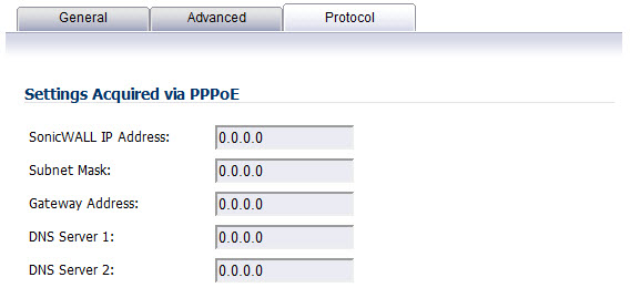
If you are configuring the WAN interface with a PPPoE, PPTP, or L2TP IP Assignment, a Protocol tab appears in the WAN interface configuration window. Depending on the protocol selected, settings acquired and client settings can be configured. Perform the steps below to configure the Protocol settings:
|
|
In the Settings Acquired section, enter your SonicWALL IP Address, Subnet Mask (PPPoE only), Gateway Address, DNS Server1, and DNS Server2. |
|
|
If you are using PPTP or L2TP, click the OK button. Your Protocol configuration is complete. |
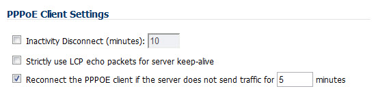
If you are using PPPoE, a Client Settings section displays in the Protocol tab:
|
|
If you want PPPoE to disconnect after a specific time period, Click the Inactivity Disconnect checkbox and enter the time period (in minutes). |
|
|
If you want to use LCP echo packets for server keep-alive, click the Strictly use LCP echo packets for server keep-alive checkbox. |
|
|
If you want the PPPoE client to reconnect to the server when traffic is not sent for a specific time period, enter the time period (in minutes) in the text field. This checkbox is selected by default. |
|
|
Click the OK button |
Configuring the NSA Expansion Pack Module Interface (NSA 2400MX and 250M only)
The SonicWALL NSA 2400MX and NSA 250M security appliances support the following optional NSA Expansion Pack modules:
These interfaces are listed in the Interface Settings table as the Mx interfaces.
|
|
|
Before attempting to insert and configure the module, you must power off the appliance. Once the appliance has been powered down, remove the rear module plate cover and insert the expansion module.Tighten the screws to secure the module, then power on the appliance. |
Log into the SonicWALL management interface. You can now begin configuring the desired expansion module. The following sections describe how to configure the
Configuring the ADSL Expansion Module
ADSL is an acronym for Asymmetric Digital Subscriber Line (or Loop). The line is asymmetric because, when connected to the ISP, the upstream and downstream speeds of transmission are different. The DSL technology allows non-voice services (data) to be provided on regular single copper wire-pair POTS connections (such as your home phone line). It allows voice calls and data to pass through simultaneously by using higher band frequencies for data transmission.
The SonicWALL ADSL module cards support only one subscriber ADSL line (one port). Two types of ADSL module cards are supported:
|
|
|
1 Port ADSL (RJ-11) Annex A – ADSL over plain old telephone service (POTS) with a downstream rate of 12.0 Mbit/s and an upstream rate of 1.3 Mbit/s. |
|
|
|
1 Port ADSL (RJ-45) Annex B – ADSL over an Integrated Services Digital Network (ISDN) with a downstream rate of 12.0 Mbit/s and an ups.tream rate of 1.8 Mbit/s. |
The following ADSL standards are supported
The ADSL module card uses 2 LEDs to indicate connectivity status. The upper green LED is the ADSL link. Its status is as follows:
The lower green LED shows the system and ADSL module activity.
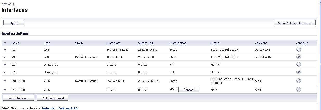
The ADSL module card is detected on boot, and assigned an interface name of M0 or M1. The interface name is based to it based on the expansion slot hosting the module card. You will see the assigned entry when you log into the Network Interfaces page.
The ADSL interface never unassigned. When plugged in, it is always present in the WAN zone and zone assignment cannot be modified by the administrator
Click on the
Configure
![]() icon to the right of the interface entry. You will see a menu with three tabs: General, Advanced, and DSL Settings. The DSL Settings tab allows you to configure ISP-specific settings for the ADSL connection.
icon to the right of the interface entry. You will see a menu with three tabs: General, Advanced, and DSL Settings. The DSL Settings tab allows you to configure ISP-specific settings for the ADSL connection.
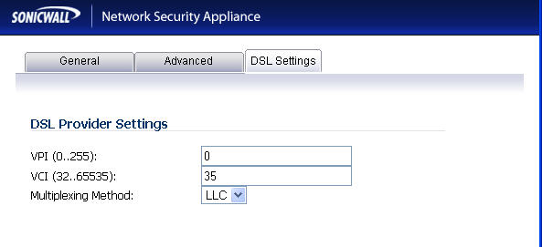
It displays the configurable DSL fields:
Virtual Channel Identifier (VCI)
Multiplexing Method (LLC or VC)
The values for these parameters should match the settings on the ISP DSLAM, and are provided by the ISP. These values vary from one ISP to another, and from country to country.
The SNWL default uses the most common values in the USA. The VPI and VCI settings are used to create the Permanent Virtual Circuit (PVC) from the NSA2400MX to the ISP DSLAM.
When finished configuring these ISP settings, click OK .
The Ethernet-specific settings on the Advanced tab, even if set, do not apply to the ADSL module. The Link Speed field in the Advanced tab has a fixed "N/A" selection, since it does not apply to ADSL. The ADSL link speed can't be customized but is predetermined by the DSL Provider.
The standard WAN ethernet settings are not affected by the presence of the ADSL module.
When the ADSL module is first plugged in, it should be added to the WAN Load Balancing
default group so that the ADSL module can be used to handle default route traffic. Go to the Failover and LB screen and click the Configure
![]() icon to edit the settings.
icon to edit the settings.
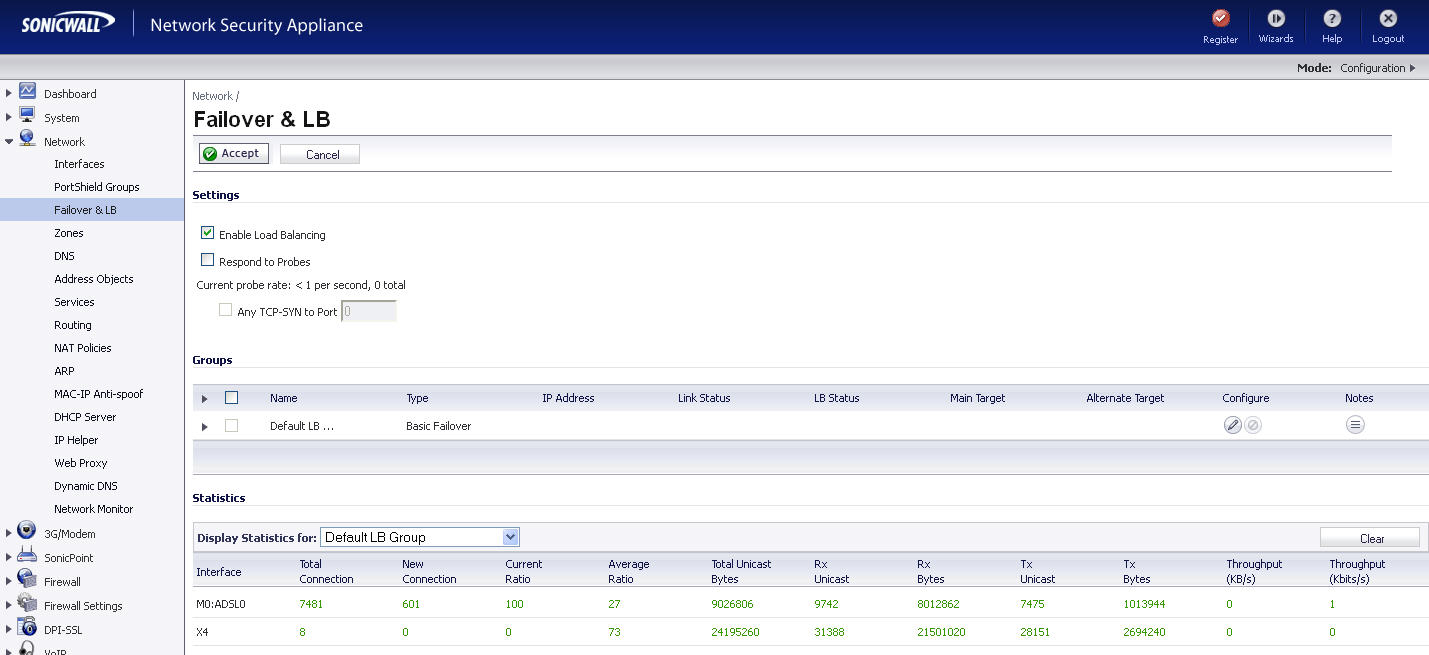
On the General menu, add the ADSL interface to the Load Balancing group. If the default primary WAN, X1, is unused or unconfigured, it can be removed for a cleaner interface configuration.
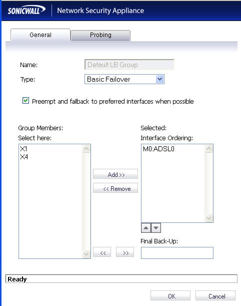
When done, click OK , and the ADSL module will be added to the group.
Configuring the T1/E1 Module
The 1-port T1/E1 Module provides the connection of a T1 or E1 (digitally multiplexed telecommunications carrier system) circuit to a SonicWALL appliance using an RJ-45 jack.
The SonicWALL T1/E1 module fully supports Point-to-Point Protocol (PPP) and Cisco HDLC encapsulation, and can connect to Cisco routers and HP ProCurve devices.
To configure the T1/E1 Module, perform the following tasks:
|
|
Click on the
Edit
|
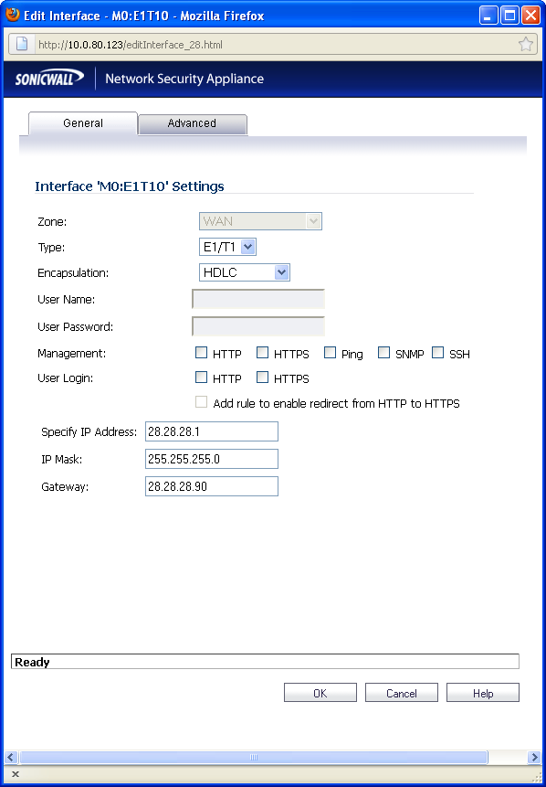
The General tab allows you to set up the type of encapsulation: PPP or HDLC, as well as the management interface type and level of user security login. The Zone setting is disabled.
|
|
Select the desired type of encapsulation: PPP, HDLC, or Cisco HDLC. If you select a type of encapsulation other than PPP, you will need to assign the IP address and netmask. |
|
|
If HDLC or Cisco HDLC is selected, assign the IP address and subnet mask for the network mask assigned to the subnet.These are auto-filled for you, but you can change them if desired. |
If you want to enable remote management of the SonicWALL security appliance from this interface, select the supported management protocol(s): HTTP , HTTPS , SSH , Ping , SNMP , and/or SSH . You can also select HTTP for management traffic. However, bear in mind that HTTP traffic is less secure than HTTPS. You can also set the level of security (HTTP or HTTPS ) at this time.
|
|
Click on the Advanced Tab. |
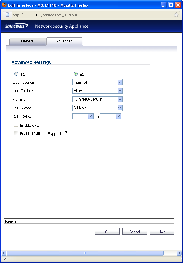
You will see two radio buttons, one for T1 and one for E1. Only one button should be selected at a time. Different Line Coding, Framing and Encapsulation configuration choices are offered, depending on the button.
|
|
Select the Clock Source: Internal or External. This selection is the same for both T1 and E1. |
If desired, you can specify the Data DSO range.
For T1, the range is 1 to 24 (default)
Each number can be individually set. For example, “5 to 15”, “1 to 1”, 1 to 20” are valid settings.
CRC is configured with an enable/disable check-box. When T1 is selected, the check-box is labeled CRC6, when E1 is selected the check-box is labeled CRC4.
You can also choose to enable multicast.
|
|
When finished with configuration, click OK . |
The T1/E1 module interface will be added to the pool of available WAN interfaces
Configuring the LAN Bypass Module
This module allows you to perform a physical bypass of the firewall when the interface is bridged to another interface with LAN bypass capability. This allows network traffic to continue flowing if an unrecoverable firewall error occurs.
|
|
Click on the
Edit
|
|
|
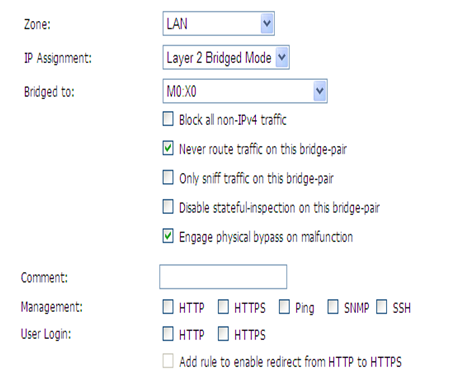
The window shows the LAN interface, and has a checkbox “ Engage Physical ByPass on Malfunction ” to enable the physical bypass feature. This is only displayed when the interface is bridged to another interface capable of performing the LAN bypass. Enabling this checkbox means that the packets between the bridged pairs will not fail, even if the firmware or NSA appliance fails. |
If the checkbox is not enabled, the ports will behave like normal Ethernet ports.
Click OK to configure the interface.
Configuring the 2 Port SFP or 4 Port Gigabit Ethernet Modules (NSA 2400MX and NSA 250M)
|
|
Click on the
Edit
|
|
|
If you’re configuring an Unassigned Interface, you can select any zone from the Zone menu. LAN is already selected in the Zone menu. |
Select one of the following LAN Network Addressing Modes from the IP Assignment menu.
|
|
|
Static - configures the interface for a network that uses static IP addresses. |
|
|
|
Transparent - configures the interface to use interfaces as the top level of the management hierarchy and span multiple interfaces. |
Depending on the option you choose from the IP Assignment menu, complete the corresponding fields that are displayed after selecting the option.
|
|
Assign the IP address and subnet mask for the network mask assigned to the subnet.These are auto-filled for you, but you can change them if desired. |
|
|
If you want to enable remote management of the SonicWALL security appliance from this interface, select the supported management protocol(s): HTTP , HTTPS , SSH , Ping , SNMP , and/or SSH . You can also select HTTP for management traffic. However, bear in mind that HTTP traffic is less secure than HTTPS. You can also use a checkbox to add a rule to redirect from HTTP to HTTPS to enforce security on the interface. |
|
|
Click OK to configure the interface. |
Configuring the Advanced Settings for the Module Interface
The Advanced tab includes settings for forcing an Ethernet speed and duplex, overriding the Default MAC address, enabling multicast support on the interface, and enabling 802.1p tagging. Packets sent out with 802.1p tagging are tagged VLAN id=0 and carry 802,1p priority information. Devices connected to this interface need to support priority frames.
Configuring Additional Interfaces
|
|
Each expansion module interface must be individually configured. These initially appear as unassigned interfaces. |
|
|
Click on the
Edit
|
For each interface, on the General tab of the Edit Interface window, select LAN from the Zone menu. Fill in the desired IP assignment. The subnet will be assigned for you. Add the desired management options and click Okay . Then configure the Advanced settings.
Configuring Link Aggregation and Port Redundancy
Both Link Aggregation and Port Redundancy are configured on the Advanced tab of the Edit Interface window in the SonicOS UI.
|
|
|
“ Link Aggregation ” - Groups multiple Ethernet interfaces together forming a single logical link to support greater throughput than a single physical interface could support. This provides the ability to send multi-gigabit traffic between two Ethernet domains. |
|
|
|
“ Port Redundancy ” - Configures a single redundant port for any physical interface that can be connected to a second switch to prevent a loss of connectivity in the event that either the primary interface or primary switch fail. |
Link Aggregation
Link Aggregation is used to increase the available bandwidth between the firewall and a switch by aggregating up to four interfaces into a single aggregate link, referred to as a Link Aggregation Group (LAG). All ports in an aggregate link must be connected to the same switch. The firewall uses a round-robin algorithm for load balancing traffic across the interfaces in a Link Aggregation Group. Link Aggregation also provides a measure of redundancy, in that if one interface in the LAG goes down, the other interfaces remain connected.
Link Aggregation is referred to using different terminology by different vendors, including Port Channel, Ether Channel, Trunk, and Port Grouping.
Link Aggregation failover
SonicWALL provides multiple methods for protecting against loss of connectivity in the case of a link failure, including High Availability (HA), Load Balancing Groups (LB Groups), and now Link Aggregation. If all three of these features are configured on a firewall, the following order of precedence is followed in the case of a link failure:
HA takes precedence over Link Aggregation. Because each link in the LAG carries an equal share of the load, the loss of a link on the Active firewall will force a failover to the Idle firewall (if all of its links remain connected). Physical monitoring needs to be configured only on the primary aggregate port.
When Link Aggregation is used with a LB Group, Link Aggregation takes precedence. LB will take over only if all the ports in the aggregate link are down.
Link Aggregation Limitations
Link Aggregation Configuration
To configure Link Aggregation, perform the following tasks:
|
|
On the Network > Interfaces page, click the configure icon for the interface that is to be designated the master of the Link Aggregation Group. The Edit Interface window displays. |
|
|
Click on the Advanced tab. |
|
|
In the Redundant/Aggregate Ports pulldown menu, select Link Aggregation . |
|
|
The Aggregate Port option is displayed with a checkbox for each of the currently unassigned interfaces on the firewall. Select up to three other interfaces to assign to the LAG. |
|
|
|
After an interface is assigned to a Link Aggregation Group, its configuration is governed by the Link Aggregation master interface and it cannot be configured independently. In the Interface Settings table, the interface's zone is displayed as "Aggregate Port" and the configuration icon is removed. |
|
|
Set the Link Speed for the interface to Auto-Negotiate . |
|
|
Click OK . |
|
|
|
Link Aggregation requires a matching configuration on the Switch. The switch's method of load balancing will very depending on the vendor. Consult the documentation for the switch for information on configuring Link Aggregation. Remember that it may be referred to as Port Channel, Ether Channel, Trunk, or Port Grouping. |
Port Redundancy
Port Redundancy provides a simple method for configuring a redundant port for a physical Ethernet port. This is a valuable feature, particularly in high-end deployments, to protect against switch failures being a single point of failure.
When the primary interface is active, it processes all traffic to and from the interface. If the primary interface goes down, the backup interface takes over all outgoing and incoming traffic. The backup interface assumes the MAC address of the primary interface and sends the appropriate gratuitous ARP on a failover event. When the primary interface comes up again, it resumes responsibility for all traffic handling duties from the backup interface.
In a typical Port Redundancy configuration, the primary and backup interfaces are connected to different switches. This provides for a failover path in case the primary switch goes down. Both switches must be on the same Ethernet domain. Port Redundancy can also be configured with both interfaces connected to the same switch.
Port Redundancy Failover
SonicWALL provides multiple methods for protecting against loss of connectivity in the case of a link failure, including High Availability (HA), Load Balancing Groups (LB Groups), and now Port Redundancy. If all three of these features are configured on a firewall, the following order of precedence is followed in the case of a link failure:
|
|
HA |
|
|
LB Group |
When Port Redundancy is used with HA, Port Redundancy takes precedence. Typically an interface failover will cause an HA failover to occur, but if a redundant port is available for that interface, then an interface failover will occur but not an HA failover. If both the primary and backup redundant ports go down, then an HA failover will occur (assuming the backup firewall has the corresponding port active).
When Port Redundancy is used with a LB Group, Port Redundancy again takes precedence. Any single port (primary or backup) failures are handled by Port Redundancy just like with HA. When both the ports are down then LB kicks in and tries to find an alternate interface.
Port Redundancy Configuration
To configure Port Redundancy, perform the following tasks:
|
|
On the Network > Interfaces page, click the configure icon for the interface that is to be designated the master of the Link Aggregation Group. The Edit Interface window displays. |
|
|
Click on the Advanced tab. |
|
|
In the Redundant/Aggregate Ports pulldown menu, select Port Redundancy . |
|
|
The Redundant Port pulldown menu is displayed, with all of the currently unassigned interfaces available. Select one of the interfaces. |
|
|
|
After an interface is selected as a Redundant Port, its configuration is governed by the primary interface and it can not be configured independently. In the Interface Settings table, the interface's zone is displayed as "Redundant Port" and the configuration icon is removed. |
|
|
Set the Link Speed for the interface to Auto-Negotiate . |
|
|
Click OK . |
Configuring Routed Mode
Routed Mode provides an alternative for NAT for routing traffic between separate public IP address ranges. Consider the following topology where the firewall is routing traffic across two public IP address ranges:
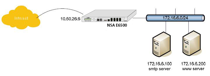
By enabling Routed Mode on the interface for the 172.16.6.0 network, all inbound and outbound traffic will be routed to the WAN interface configured for the 10.50.26.0 network.
To configure Routed Mode, perform the following steps:
|
|
Navigate to the Network > Interfaces page. |
|
|
Click on the configure icon for the appropriate interface. The Edit Interface window displays. |
|
|
Click on the Advanced tab. |
|
|
Under the Expert Mode Settings heading, select the Use Routed Mode - Add NAT Policy to prevent outbound\inbound translation checkbox to enable Routed Mode for the interface. |
|
|
In the Set NAT Policy's outbound\inbound interface to pulldown menu, select the WAN interface that is to be used to route traffic for the interface. |
|
|
Click OK . |
The firewall then creates two “No-NAT” policies for both the configured interface and the selected WAN interface. These policies override any more general Many to One NAT policies that may be configured for the interfaces.