Configuring the
U0/U1/M0 External 3G/Modem Interface
The SonicWALL security appliances with a USB port support an external 3G/mobile or analog
modem interface. Depending on your appliance, when an analog modem or 3G device is installed prior to starting the appliance, it will be listed as the U0, U1, or M0 (NSA 240 only) interface on the Network > Interfaces
page.
The U0/U1/M0 interface must be initally configured on the on the
3G
or Modem
tab in the left-side navigation bar. Once you have a created configuration profile for the interface, the configuration can be modified from the N
etwork > Interfaces
page or For additional information on 3G or analog modem external interfaces, see “3G/Modem”
.
To manually initiate a connection on the U0/U1/M0 external 3G/modem interface, perform the
following steps:
|
1.
|
On the
Network > Interfaces
page, click on the Manage
button for the U0/U1/M0 interface.
|
To configure the U0/U1/M0 interface from the
Network > Interfaces
page, perform the following steps.
|
3.
|
Select the appropriate
Management/User Login
options to enable remote management of the SonicWALL appliance over the 3G interface.
|
You can select any of the supported management protocol(s):
HTTPS
, Ping
, SNMP
, and/or SSH
. You can also select HTTP
for management traffic. However, bear in mind that HTTP traffic is less secure than HTTPS.
|
4.
|
Select
Add rule to enable redirect from HTTP to HTTPS
to have the SonicWALL automatically convert HTTP requests to HTTPS requests for added security.
|
|
1.
|
Check the
Enable Remotely Triggered Dial-Out
checkbox to enable network administrators to remotely initiate a WAN modem connection. For more information, see “Remotely Triggered Dial-Out”
.
|
|
3.
|
In the
Max Hosts
field, enter the maximum number of hosts to allow when this interface is connected. The default value is “0”, which allows an unlimited number of nodes.
|
|
4.
|
Click the
Enable Egress Bandwidth Management
checkbox to enable bandwidth management policy enforcement on outbound traffic.
|
|
5.
|
Click the
Enable Ingress Bandwidth Management
checkbox to enable bandwidth management policy enforcement on inbound traffic.
|
|
6.
|
Select a
Compression Multiplier
from the drop-down list as necessary to appropriately adjust bandwidth calculations if the dial-up device performs compression.
|
|
7.
|
Select the
Enable flow reporting
checkbox to have the data for flows on this interface reported to Flow Reporting and the
Real-Time Monitor.
|
C
onfiguring SonicWALL PortShield Interfaces
PortShield architecture enables you to configure some or all of the LAN ports into separate
security contexts, providing protection not only from the WAN and DMZ, but between devices inside your network as well. In effect, each context has its own wire-speed PortShield that enjoys the protection of a dedicated, deep packet inspection firewall.
PortShield is supported on SonicWALL TZ Series and NSA 240 appliances.
You can assign any combination of ports into a PortShield interface. All ports you do not assign
to a PortShield interface are assigned to the LAN interface.
To configure a PortShield interface, perform the following steps:
|
Step 2
|
C
lick the Configure
button for the interface you want to configure. The Edit Interface window displays.
|
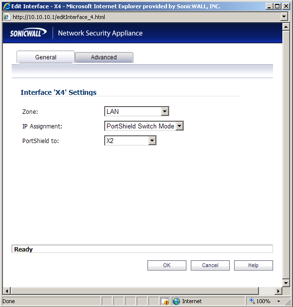
|
Step 3
|
In the
Zone
pulldown menu, select on a zone type option to which you want to map the interface.
|
|
Step 4
|
In the
IP Assignment
pulldown menu, select PortShield Switch Mode
.
|
|
Step 5
|
In the
PortShield to
pulldown menu, select the interface you want to map this port to. Only ports that match the zone you have selected are displayed.
|
VLAN subinterfaces are supported on SonicWALL NSA series appliances. When you add a
VLAN subinterface, you need to assign it to a zone, assign it a VLAN Tag, and assign it to a physical interface. Based on your zone assignment, you configure the VLAN subinterface the same way you configure a physical interface for the same zone.
Your configuration choices for the network settings of the subinterface depend on the zone
you select.
|
|
•
|
LAN
, DMZ
, or a custom zone of Trusted type: Static
or Transparent
|
|
|
•
|
WLAN
or a custom Wireless zone: static IP only (no IP Assignment list).
|
See the following sections:
The following settings need to be configured on your SonicWALL UTM appliance prior to using
it in most of the Layer 2 Bridge Mode topologies.
When the appliance is successfully registered, go to the
System > Licenses
page and click Synchronize
under Manage Security Services Online
. This will contact the SonicWALL licensing server and ensure that the appliance is properly licensed.
To check licensing status, go to the
System > Status
page and view the license status of all the UTM services (Gateway Anti-Virus, Anti-Spyware, and Intrusion Prevention).
When using a SonicWALL UTM appliance in Layer 2 Bridge Mode in a network configuration
where another device is acting as the DHCP server, you must first disable its internal DHCP engine, which is configured and running by default. On the Network > DHCP Server
page, clear the Enable DHCP Server
check box, and then click on the Accept
button at the top of the screen.
On the
System > Administration
page, make sure the checkbox next to Enable SNMP
is checked, and then click on the Accept
button at the top of the screen.
Then, click the
Configure
button. On the SNMP Settings
page, enter all the relevant information for your UTM appliance: the GET and TRAP SNMP community names that the SNMP server expects, and the IP address of the SNMP server. Click OK
to save and activate the changes.
On the
Network > Interfaces
page, enable SNMP and HTTP/HTTPS on the interface through which you will be managing the appliance.
On the
Log > Syslog
page, click on the Add
button and create an entry for the syslog server. Click OK
to save and activate the change.
On the
Network > Zones
page, for each zone you will be using, make sure that the UTM services are activated.
Then, on the
Security Services
page for each UTM service, activate and configure the settings that are most appropriate for your environment.
An example of the Gateway Anti-Virus settings is shown below:
An example of the Intrusion Prevention settings is shown below:
An example of the Anti-Spyware settings is shown below:
If you plan to manage the appliance from a different zone, or if you will be using a server such
as the HP PCM+/NIM server for management, SNMP, or syslog services, create access rules for traffic between the zones. On the Firewall > Access Rules
page, click on the icon for the intersection of the zone of the server and the zone that has users and servers (your environment may have more than one of these intersections). Create a new rule to allow the server to communicate with all devices in that zone.
On the
Log > Categories
page, set the Logging Level
to Informational
and the Alert Level
to Critical
. Click Accept
to save and activate the change.
Then, go to the
Log > Name Resolution
page and set the Name Resolution Method
to DNS
then NetBios
. Click Accept
to save and activate the change.
In the case where you are using a HP PCM+/NIM system, if it will be managing a HP ProCurve
switch on an interface assigned to a WLAN/Wireless zone, you will need to deactivate two features, otherwise you will not be able to manage the switch. Go to the Network > Zones
page and select your Wireless zone. On the Wireless
tab, clear the checkboxes next to Only allow
traffic generated by a SonicPoint
and WiFiSec Enforcement
. Click OK
to save and activate the change.
Refer to the
“L2 Bridge Interface Zone Selection” section
for choosing a topology that best suits your network. In this example, we will be using a topology that most closely resembles the Simple L2 Bridge Topology.
Choose an interface to act as the Primary Bridge Interface. Refer to the
“L2 Bridge Interface Zone Selection” section
for information in making this selection. In this example, we will use X1 (automatically assigned to the Primary WAN):
|
Step 1
|
Select the
Network
tab, Interfaces
folder from the navigation panel.
|
Choose an interface to act as the Secondary Bridge Interface. Refer to the
L2 Bridge Interface
Zone Selection
for information in making this selection. In this example, we will use X0 (automatically assigned to the LAN):
|
Step 1
|
On the
Network > Interfaces
page, click the Configure  icon in the right column of the X0 (LAN) interface. icon in the right column of the X0 (LAN) interface.
|
|
Step 2
|
In the
IP Assignment
drop-down list, select Layer 2 Bridged Mode
.
|
|
Step 3
|
In the
Bridged to
drop-down list, select the X1
interface.
|
|
|
–
|
Select
Block listed VLANs (blacklist)
from the drop-down list and add the VLANs you wish to block from the left pane to the right pane. All VLANs added to the right pane will be blocked, and all VLANs remaining in the left pane will be allowed.
|
|
|
–
|
Select
Allow listed VLANs (whitelist) from the drop-down list and add the VLANs you wish to explicitly allow from the left pane to the right pane. All VLANs added to the right pane will be allowed, and all VLANs remaining in the left pane will be blocked.
|
The
Network
> Interfaces
page displays the updated configuration:
You may now apply security services to the appropriate zones, as desired. In this example, they
should be applied to the LAN, WAN, or both zones.
VLANs are supported on SonicWALL NSA series appliances. When a packet with a VLAN tag
arrives on a physical interface, the VLAN ID is evaluated to determine if it is supported. The VLAN tag is stripped, and packet processing continues as it would for any other traffic. A simplified view of the inbound and outbound packet path includes the following potentially reiterative steps:
At this point, if the packet has been validated as acceptable traffic, it is forwarded to its
destination. The packet egress path includes:
On egress, if the route policy lookup determines that the gateway interface is a VLAN
subinterface, the packet is tagged (encapsulated) with the appropriate VLAN ID header. The creation of VLAN subinterfaces automatically updates the SonicWALL’s routing policy table:
The auto-creation of NAT policies, Access Rules with regard to VLAN subinterfaces behave
exactly the same as with physical interfaces. Customization of the rules and policies that govern the traffic between VLANs can be performed with customary SonicOS ease and efficiency.
When creating a zone (either as part of general administration, or as a step in creating a
subinterface), a checkbox will be presented on the zone creation page to control the auto-creation of a GroupVPN for that zone. By default, only newly created Wireless type zones will have ‘Create GroupVPN for this zone’ enabled, although the option can be enabled for other zone types by selecting the checkbox during creation.
Management of security services between VLAN subinterfaces is accomplished at the zone
level. All security services are configurable and applicable to zones comprising physical interfaces, VLAN subinterfaces, or combinations of physical and VLAN subinterfaces.
Gateway Anti-Virus and Intrusion Prevention Services between the different workgroups can
easily be employed with the use of VLAN segmentation, obviating the need for dedicated physical interfaces for each protected segment.
VLAN support enables organizations to offer meaningful internal security (as opposed to simple
packet filtering) between various workgroups, and between workgroups and server farms without having to use dedicated physical interfaces on the SonicWALL.
Here the ability to assign VLAN subinterfaces to the WAN zone, and to use the WAN client
mode (only Static addressing is supported on VLAN subinterfaces assigned to the WAN zone) is illustrated, along with the ability to support WAN Load Balancing and failover. Also demonstrated is the distribution of SonicPoints throughout the network by means of connecting them to access mode VLAN ports on workgroup switches. These switches are then backhauled to the core switch, which then connects all the VLANs to the appliance via a trunk link.
When configuring a VPN on an interface that is also configured for Layer 2 Bridge mode, you
must configure an additional route to ensure that incoming VPN traffic properly traverses the SonicWALL security appliance. Navigate to the Network > Routing
page, scroll to the bottom of the page, and click on the Add
button. In the Add Route Policy
window, configure the route as follows:
|
|
•
|
Destination:
custom-VPN-address-object
(This is the address object for the local VPN tunnel IP address range.)
|
To configure the SonicWALL NSA appliance for IPS Sniffer Mode, you will use two interfaces
in the same zone for the L2 Bridge-Pair. You can use any interfaces except the WAN interface. For this example, we will use X2 and X3 for the Bridge-Pair, and configure them to be in the LAN zone. The WAN interface (X1) is used by the SonicWALL appliance for access to the SonicWALL Data Center as needed. The mirrored port on the switch will connect to one of the interfaces in the Bridge-Pair.
This section contains the following topics:
|
Step 1
|
Select the
Network
tab, Interfaces
folder from the navigation panel.
|
Note that you do not need to configure settings on the Advanced or VLAN Filtering tabs.
Our example continues with X3 as the secondary bridge interface.
|
Step 1
|
Select the
Network
tab, Interfaces
folder from the navigation panel.
|
Note that you do not need to configure settings on the Advanced or VLAN Filtering tabs.
|
Step 5
|
In the
Bridged to
drop-down list, select the X2
interface.
|
|
Step 6
|
Do not enable the
Block all non-IPv4 traffic
setting if you want to monitor non-IPv4 traffic.
|
|
Step 7
|
Select
Never route traffic on this bridge-pair
to ensure that the traffic from the mirrored switch port is not sent back out onto the network. (The Never route traffic on this bridge-pair
setting is known as Captive-Bridge Mode.)
|
|
Step 8
|
Select
Only sniff traffic on this bridge-pair
to enable sniffing or monitoring of packets that arrive on the L2 Bridge from the mirrored switch port.
|
|
Step 9
|
Select
Disable stateful-inspection on this bridge-pair
to allow TCP connections to pass
through the SonicWALL even if the device has not seen a valid and complete TCP handshake
sequence. This can be used for networks employing asymmetric packet paths for incoming and
outgoing traffic in which the SonicWALL does not see all traffic of the TCP flow. Use of this setting
is not recommended as it limits the SonicWALL’s ability to enforce TCP stateful and other
protections for the secured network.
|
When SNMP is enabled, SNMP traps are automatically triggered for many events that are
generated by SonicWALL Security Services such as Intrusion Prevention and Gateway Anti-Virus.
More than 50 IPS and GAV events currently trigger SNMP traps. The
SonicOS Log Event
Reference Guide
contains a list of events that are logged by SonicOS, and includes the SNMP trap number where applicable. The guide is available online at
http://www.sonicwall.com/us/Support.html
by typing Log Event
into the Search field at the top of the page.
To determine the traps that are possible when using IPS Sniffer Mode with Intrusion Prevention
enabled, search for Intrusion
in the table found in the Index of Log Event Messages section in the SonicOS Log Event Reference Guide
. The SNMP trap number, if available for that event, is printed in the SNMP Trap Type column of the table.
To determine the possible traps with Gateway Anti-Virus enabled, search the table for
Security
Services
, and view the SNMP trap number in the SNMP Trap Type column.
To enable and configure SNMP:
|
Step 1
|
Select the
System
tab, Administration
folder from the navigation panel.
|
|
Step 3
|
Select the
Enable SNMP
checkbox. The Configure button becomes active.
|
|
Step 4
|
Click
Configure
. The SNMP Settings dialog box is displayed.
|
The settings that you enable in this section will control what type of malicious traffic you detect
in IPS Sniffer Mode. Typically you will want to enable Intrusion Prevention, but you may also want to enable other Security Services such as Gateway Anti-Virus or Anti-Spyware.
To enable Security Services, your SonicWALL must be licensed for them and the signatures
must be downloaded from the SonicWALL Data Center. For complete instructions on enabling and configuring IPS, GAV, and Anti-Spyware, see the Security Services section in this guide.
You can configure logging to record entries for attacks that are detected by the SonicWALL.
To enable logging, perform the following steps:
|
Step 1
|
Select the
Log
tab, Categories
folder from the navigation panel.
|
Use a standard Cat-5 Ethernet cable to connect the mirrored switch port to either interface in
the Bridge-Pair. Network traffic will automatically be sent from the switch to the SonicWALL where it can be inspected.
Consult the switch documentation for instructions on setting up the mirrored port.
Connect the WAN port on the SonicWALL, typically port X1, to your gateway or to a device with
access to the gateway. The SonicWALL communicates with the SonicWALL Data Center automatically. For detailed instructions on configuring the WAN interface, see “Configuring a WAN Interface”
.
Adding to the broad collection of traditional modes of SonicOS interface operation, including all
LAN modes (Static, NAT, Transparent Mode, L2 Bridge Mode, Portshield Switch Mode), and all WAN modes (Static, DHCP, PPPoE, PPTP, and L2TP), SonicOS 5.8 introduces Wire-Mode, which provides four new methods non‑disruptive, incremental insertion into networks.
Restrict analysis at resource limit
|
|
|
|
Bypass Mode
|
Bypass Mode allows for the quick and relatively non-interruptive
introduction of Wire Mode into a network. Upon selecting a point of insertion into a network (e.g. between a core switch and a perimeter firewall, in front of a VM server farm, at a transition point between data classification domains) the SonicWALL security appliance is inserted into the physical data path, requiring a very short maintenance window. One or more pairs of switch ports on the appliance are used to forward all packets across segments at full line rates. While Bypass Mode does not offer any inspection or firewalling, this mode allows the administrator to physically introduce the SonicWALL security appliance into the network with a minimum of downtime and risk, and to obtain a level of comfort with the newly inserted component of the networking and security infrastructure. The administrator can then transition from Bypass Mode to Inspect or Secure Mode instantaneously through a simple user-interface driven reconfiguration.
|
|
Inspect Mode
|
Inspect Mode extends Bypass Mode without functionally altering the
low-risk, zero-latency packet path. Packets continue to pass through the SonicWALL security appliance, but they are also mirrored to the multi-core RF-DPI engine for the purposes of passive inspection, classification, and flow reporting. This reveals the appliance’s Application Intelligence and threat detection capabilities without any actual intermediate processing.
When Inspect Mode is selected, the
Restrict analysis at resource limit
option specifies whether all traffic is inspected. When this option is enabled (which is the default), the appliance scans the maximum number of packets it can process. The remaining packets are allowed to pass without inspection. If this option is disabled, traffic will be throttled in the flow of traffic exceeds the firewalls inspection ability.
|
|
Note
|
Disabling the
Restrict analysis at resource limit
option will reduce throughput if the rate of traffic exceeds the appliance’s ability to scan all traffic.
|
|
|
Secure Mode
|
Secure Mode is the progression of Inspect Mode, actively interposing
the SonicWALL security appliance’s multi-core processors into the packet processing path. This unleashes the inspection and policy engines’ full-set of capabilities, including Application Intelligence and Control, Intrusion Prevention Services, Gateway and Cloud-based Anti-Virus, Anti-Spyware, and Content Filtering. Secure Mode affords the same level of visibility and enforcement as conventional NAT or L2 Bridge mode deployments, but without any L3/L4 transformations, and with no alterations of ARP or routing behavior. Secure Mode thus provides an incrementally attainable NGFW deployment requiring no logical and only minimal physical changes to existing network designs.
|
|
Tap Mode
|
Tap Mode provides the same visibility as Inspect Mode, but differs from
the latter in that it ingests a mirrored packet stream via a single switch port on the SonicWALL security appliance, eliminating the need for physically intermediated insertion. Tap Mode is designed for use in environments employing network taps, smart taps, port mirrors, or SPAN ports to deliver packets to external devices for inspection or collection. Like all other forms of Wire Mode, Tap Mode can operate on multiple concurrent port instances, supporting discrete streams from multiple taps.
|
To summarize the key functional differences between modes of interface configuration:
|
|
Note
|
When operating in Wire-Mode, the SonicWALL security appliance’s dedicated
“Management” interface will be used for local management. To enable remote management and dynamic security services and application intelligence updates, a WAN interface (separate from the Wire-Mode interfaces) must be configured for Internet connectivity. This is easily done given that SonicOS supports interfaces in mixed-modes of almost any combination.
|
To configure an interface for Wire Mode, perform the following steps:
|
1.
|
On the
Network > Interfaces
page, click the Configure button for the interface you want to configure for Wire Mode.
|
|
2.
|
In the
Zone
pulldown menu, select LAN
.
|
|
5.
|
In the
Wire Mode Type
pulldown menu, select the appropriate mode:
|
|
6.
|
When
Inspect Mode
is selected, the Restrict analysis at resource limit
option is displayed. It is enabled by default. When this option is enabled, the appliance scans the maximum number of packets it can process. The remaining packets are allowed to pass without inspection. If this option is disabled, traffic will be throttled in the flow of traffic exceeds the firewalls inspection ability.
|
|
|
Note
|
Disabling the
Restrict analysis at resource limit
option will reduce throughput if the rate of traffic exceeds the appliance’s ability to scan all traffic.
|
|
7.
|
In the
Paired Interface
pulldown menu, select the interface that will connect to the upstream firewall. The paired interfaces must be of the same type (two 1 GB interfaces or two 10 GB interfaces).
|