Hardware_Failover_haConfig1
The following sections describe how to configure the High Availability > Settings page:
• Active/Idle High Availability Settings
• Active/Active High Availability Settings
Note For more information on High Availability, see High Availability Overview and Active/Idle and Active/Active DPI HA Prerequisites. If your Active/Active Clustering environment will use VPN or NAT, see Configuring VPN and NAT with Active/Active Clustering after you have finished the Active/Active configuration.
Active/Idle High Availability Settings
The configuration tasks on the High Availability > Settings page are performed on the Primary unit and then are automatically synchronized to the Secondary.To configure settings for Active/Standby on the High Availability > Settings page, perform the following steps:
Step 1 Login as an administrator to the SonicOS user interface on the Primary SonicWALL.
Step 2 In the left navigation pane, navigate to High Availability > Settings. The General tab is displayed.
Step 3 In the Mode pull-down menu, select Active/Idle.
Step 4 To configure Stateful High Availability select Enable Stateful Synchronization. Fields are displayed with recommended settings for the Heartbeat Interval and Probe Interval fields. The settings shown are minimum recommended values. Lower values may cause unnecessary failovers, especially when the SonicWALL is under a heavy load. You can use higher values if your SonicWALL handles a lot of network traffic.
When Stateful High Availability is not enabled, session state is not synchronized between the Primary and Secondary SonicWALL SuperMassives. If a failover occurs, any session that had been active at the time of failover needs to be renegotiated.
Step 5 To configure the High Availability Pair so that the Primary unit takes back the Primary role once it restarts after a failure, select Enable Preempt Mode. Preempt mode is recommended to be disabled when enabling Stateful High Availability, because preempt mode can be over-aggressive about failing over to the Secondary appliance.
Step 6 Select the Enable Virtual MAC checkbox to allow the Primary and Secondary appliances to share a single MAC address. This greatly simplifies the process of updating network ARP tables and caches when a failover occurs. Only the switch to which the two appliances are connected needs to be notified. All outside devices will continue to route to the single shared MAC address.
Step 7 Click the HA Devices tab to configure the Primary and Secondary appliance serial number.
Step 8 Enter the Serial Number of the Secondary Device.
Step 9 Click the HA Interfaces tab.
Step 10 Select the interface for the HA Control Interface. This option is grayed out if the appliance detects that the interface is already configured.
Step 11 Select the interface for the Active/Active DPI Interface. This option is grayed out if the appliance detects that the interface is already configured.
Step 12 When finished with all High Availability configuration, click Apply. All settings will be synchronized to the Idle unit, and the Idle unit will reboot.
Active/Active High Availability Settings
There are three options for configuring Active/Active High Availability:
• Active/Active DPI High Availability
• Active/Active Clustering High Availability
• Active/Active DPI Clustering High Availability
Step 1 In the left navigation pane, navigate to High Availability > Settings. The General tab is displayed.
Step 2 In the Mode pull-down menu, select Active/Active DPI.
Step 3 The Enable Stateful Synchronization option is automatically enabled for Active/Active DPI, and the option is grayed out.
Step 4 Under normal conditions, the Enable Preempt Mode option should be disabled for Active/Active DPI. This option instructs the Primary unit takes back the Primary role once it restarts after a failure; thus, this option only applies to Active/Standby configurations.
Step 5 Select the Enable Virtual MAC checkbox to allow both appliances in the HA pair to share a single MAC address. This greatly simplifies the process of updating network ARP tables and caches when a failover occurs. Only the switch to which the two appliances are connected needs to be notified. All outside devices will continue to route to the single shared MAC address.
Step 6 Click the HA Devices tab to.
Step 7 Enter the Serial Number of the Secondary Device.
Step 8 Click the HA Interfaces tab.
Step 9 Select the interface for the HA Control Interface. This option is grayed out if the appliance detects that the interface is already configured.
Step 10 Select the interface number for the Active/Active DPI Interface. This option is grayed out if the appliance detects that the interface is already configured.
Step 11 Select the Active/Active DPI Interface. This interface will be used for transferring data between the two units during Active/Active DPI processing. Only unassigned, available interfaces appear in the list. The connected interfaces must be the same number on both appliances, and must initially appear as unused, unassigned interfaces in the Network > Interfaces page. For example, you could connect X5 on the Primary unit to X5 on the Secondary if X5 is an unassigned interface. After enabling Active/Active DPI, the connected interface will have a Zone assignment of HA Data-Link.
Step 12 When finished with all High Availability configuration, click Apply. All settings will be synchronized to the Idle unit, and the Idle unit will reboot.
Active/Active Clustering High Availability allows for the configuration of up to four HA cluster nodes for failover and load sharing. Each node can contain either a single appliance or an HA pair configured for standard failover, stateful HA failover, or Active/Active capabilities.
Step 13 In the left navigation pane, navigate to High Availability > Settings. The General tab is displayed.In the Mode pull-down menu, select Active/Active Clustering.
Step 14 The Enable Stateful Synchronization option is automatically enabled for Active/Active Clustering.
Step 15 Select the Generate/Overwrite Secondary Firmware and Settings When Upgrading Firmware checkbox to automatically create a secondary of the firmware and configuration settings when yo upload new firmware to the appliance. As the Master Node synchronizes new firmware to other appliances in the cluster, secondarys will be created on those appliances.
Step 16 Click the HA Devices tab to configure the Active/Active cluster information.
Step 17 In the table, enter the serial numbers of the appliances in each Cluster Node.
Step 18 Enter the rank that Cluster Node 1 holds for each Virtual Group in the Virtual Group X Rank fields to the right of the serial numbers. By default, Cluster Node 1 is the Owner of Group 1, and typically is ranked as Standby for Group 2. To exclude an appliance from a cluster, select None for the Virtual Group X Rank.
Step 19 In the second row, enter the rank that Cluster Node 2 holds for each Virtual Group in the Virtual Group X Rank fields to the right of the serial numbers.
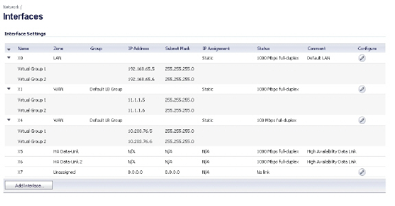
On the Network > Interfaces page, Virtual Group 1 is displayed with its corresponding virtual IP addresses. The Active/Active DPI Interface(s) are shown as members of the HA Data-Link zone.
Step 20 Click the HA Interfaces tab. Select the Active/Active Cluster Link interface. This interface will be used for transferring data between the two units during Active/Active processing. Only unassigned, available interfaces appear in the list.
Step 21 When finished with all High Availability configuration, click Apply. All settings will be synchronized to the Idle unit, and the Idle unit will reboot.
Active/Active DPI Clustering High Availability allows for the configuration of up to four HA cluster nodes for failover and load sharing, where the nodes load balance the application of DPI security services to network traffic. To configure your SonicWALL deployment to use Active/Active Clustering, perform the following steps:
Step 1 Login to the Primary unit of the Master Cluster Node and navigate to the High Availability > Settings page. The General tab is displayed.
Step 2 If you have physically connected the Active/Active DPI Interface as described in Physically Connecting Your Appliances, you are ready to configure Active/Active DPI in the SonicOS management interface. In the Mode pull-down menu, select Active/Active DPI Clustering.
Step 3 The Enable Stateful Synchronization option is automatically enabled for Active/Active DPI Clustering.
Step 4 Select the Generate/Overwrite Secondary Firmware and Settings When Upgrading Firmware checkbox to automatically create a secondary of the firmware and configuration settings when yo upload new firmware to the appliance. As the Master Node synchronizes new firmware to other appliances in the cluster, secondarys will be created on those appliances.
Step 5 Click the HA Devices tab to configure the Active/Active cluster information.
Step 6 For the HA Secondary option at the top of the tab, select Internal if the configured secondary appliance is part of the cluster node for this appliance. Select External if the configured secondary appliance is part of a different cluster node.
Step 7 In the table, enter the serial numbers of the appliances in each Cluster Node.
Step 8 Enter the rank that Cluster Node 1 holds for each Virtual Group in the Virtual Group X Rank fields to the right of the serial numbers. By default, Cluster Node 1 is the Owner of Group 1, and typically is ranked as Standby for Group 2. To exclude an appliance from a cluster, select None for the Virtual Group X Rank.
Step 9 In the second row, enter the rank that Cluster Node 2 holds for each Virtual Group in the Virtual Group X Rank fields to the right of the serial numbers.
On the Network > Interfaces page, Virtual Group 1 is displayed with its corresponding virtual IP addresses. The Active/Active DPI Interface(s) are shown as members of the HA Data-Link zone.

Step 10 Click the HA Interfaces tab. Select the interface for the HA Control Interface. This option is grayed out if the appliance detects that the interface is already configured.
Step 11 Select the interface for the Active/Active DPI Interface.This option is grayed out if the appliance detects that the interface is already configured.
Step 12 Select the Active/Active DPI Interface. This interface will be used for transferring data between the two units during Active/Active DPI processing. Only unassigned, available interfaces appear in the list.
Step 13 Select the Active/Active Cluster Link interface.
Step 14 When finished with all High Availability configuration, click Apply. All settings will be synchronized to the Idle unit, and the Idle unit will reboot.