High_Availability
This chapter provides conceptual information and describes how to configure High Availability (HA) in SonicOS. The following sections provide overviews of SonicWALL’s implementation of HA:
• Stateful Synchronization Overview
• Active/Active DPI HA Overview
• Active/Active Clustering Full-Mesh Overview
The following sections describe how to prepare, configure, and verify HA and Active/Active Clustering:
• Active/Idle and Active/Active DPI HA Prerequisites
• Configuring Active/Active Clustering and HA
• Viewing FIB routes in the GUI
• Configuring VPN and NAT with Active/Active Clustering
• Configuring Active/Active Clustering Full Mesh
HA allows two identical SonicWALL SuperMassives running SonicOS to be configured to provide a reliable, continuous connection to the public Internet.One SonicWALL device is configured as the Primary unit, and an identical SonicWALL device is configured as the Secondary unit. In the event of the failure of the Primary SonicWALL, the Secondary SonicWALL takes over to secure a reliable connection between the protected network and the Internet. Two appliances configured in this way are also known as a High Availability Pair (HA Pair).
HA provides a way to share SonicWALL licenses between two SonicWALL SuperMassives when one is acting as a high availability system for the other. To use this feature, you must register the SonicWALL appliances on MySonicWALL as Associated Products. Both appliances must be the same SonicWALL model.
Active/Idle HA provides the following benefits:
• Increased network reliability – In a High Availability configuration, the Secondary appliance assumes all network responsibilities when the Primary unit fails, ensuring a reliable connection between the protected network and the Internet.
• Cost-effectiveness – High Availability is a cost-effective option for deployments that provide high availability by using redundant SonicWALL SuperMassives. You do not need to purchase a second set of licenses for the Secondary unit in a High Availability Pair.
• Virtual MAC for reduced convergence time after failover – The Virtual MAC address setting allows the HA Pair to share the same MAC address, which dramatically reduces convergence time following a failover. Convergence time is the amount of time it takes for the devices in a network to adapt their routing tables to the changes introduced by high availability. By default, the Virtual MAC address is provided by the SonicWALL firmware and is different from the physical MAC address of either the Primary or Secondary appliances.
HA requires one SonicWALL device configured as the Primary SonicWALL, and an identical SonicWALL device configured as the Secondary SonicWALL. During normal operation, the Primary SonicWALL is in an Active state and the Secondary SonicWALL in an Idle state. If the Primary device loses connectivity, the Secondary SonicWALL transitions to Active mode and assumes the configuration and role of Primary, including the interface IP addresses of the configured interfaces. After a failover to the Secondary appliance, all the pre-existing network connections must be re-established, including the VPN tunnels that must be re-negotiated.
The failover applies to loss of functionality or network-layer connectivity on the Primary SonicWALL. The failover to the Secondary SonicWALL occurs when critical services are affected, physical (or logical) link failure is detected on monitored interfaces, or when the Primary SonicWALL loses power. The Primary and Secondary SonicWALL devices are currently only capable of performing Active/Idle High Availability or Active/Active UTM – complete Active/Active high availability is not supported at present.
For SonicWALL appliances that support PortShield, High Availability requires that PortShield is disabled on all interfaces of both the Primary and Secondary appliances prior to configuring the HA Pair. Besides disabling PortShield, SonicWALL SuperMassive configuration is performed on only the Primary SonicWALL, with no need to perform any configuration on the Secondary SonicWALL. The Secondary SonicWALL maintains a real-time mirrored configuration of the Primary SonicWALL via an Ethernet link between the designated HA ports of the appliances. If the firmware configuration becomes corrupted on the Primary SonicWALL, the Secondary SonicWALL automatically refreshes the Primary SonicWALL with the last-known-good copy of the configuration preferences.
There are two types of synchronization for all configuration settings: incremental and complete. If the timestamps are in sync and a change is made on the Active unit, an incremental synchronization is pushed to the Idle unit. If the timestamps are out of sync and the Idle unit is available, a complete synchronization is pushed to the Idle unit. When incremental synchronization fails, a complete synchronization is automatically attempted.
• Primary - Describes the principal hardware unit itself. The Primary identifier is a manual designation, and is not subject to conditional changes. Under normal operating conditions, the Primary hardware unit operates in an Active role.
• Secondary - Describes the subordinate hardware unit itself. The Secondary identifier is a relational designation, and is assumed by a unit when paired with a Primary unit. Under normal operating conditions, the Secondary unit operates in an Idle mode. Upon failure of the Primary unit, the Secondary unit will assume the Active role.
• Active - Describes the operative condition of a hardware unit. The Active identifier is a logical role that can be assumed by either a Primary or Secondary hardware unit.
• Idle - Describes the passive condition of a hardware unit. The Idle identifier is a logical role that can be assumed by either a Primary or Secondary hardware unit. The Idle unit assumes the Active role in the event of determinable failure of the Active unit.
• Failover - Describes the actual process in which the Idle unit assumes the Active role following a qualified failure of the Active unit. Qualification of failure is achieved by various configurable physical and logical monitoring facilities described throughout the Task List section.
• Preempt - Applies to a post-failover condition in which the Primary unit has failed, and the Secondary unit has assumed the Active role. Enabling Preempt will cause the Primary unit to seize the Active role from the Secondary after the Primary has been restored to a verified operational state.
Crash Detection
The HA feature has a thorough self-diagnostic mechanism for both the Primary and Secondary SonicWALL SuperMassives. The failover to the Secondary SonicWALL occurs when critical services are affected, physical (or logical) link detection is detected on monitored interfaces, or when the SonicWALL loses power.
The self-checking mechanism is managed by software diagnostics, which check the complete system integrity of the SonicWALL device. The diagnostics check internal system status, system process status, and network connectivity. There is a weighting mechanism on both sides to decide which side has better connectivity, used to avoid potential failover looping.
Critical internal system processes such as NAT, VPN, and DHCP (among others) are checked in real time. The failing service is isolated as early as possible, and the failover mechanism repairs it automatically.
The Virtual MAC address allows the High Availability pair to share the same MAC address, which dramatically reduces convergence time following a failover. Convergence time is the amount of time it takes for the devices in a network to adapt their routing tables to the changes introduced by high availability.
Without Virtual MAC enabled, the Active and Idle appliances each have their own MAC addresses. Because the appliances are using the same IP address, when a failover occurs, it breaks the mapping between the IP address and MAC address in the ARP cache of all clients and network resources. The Secondary appliance must issue an ARP request, announcing the new MAC address/IP address pair. Until this ARP request propagates through the network, traffic intended for the Primary appliance’s MAC address can be lost.
The Virtual MAC address greatly simplifies this process by using the same MAC address for both the Primary and Secondary appliances. When a failover occurs, all routes to and from the Primary appliance are still valid for the Secondary appliance. All clients and remote sites continue to use the same Virtual MAC address and IP address without interruption.
By default, this Virtual MAC address is provided by the SonicWALL firmware and is different from the physical MAC address of either the Primary or Secondary appliances. This eliminates the possibility of configuration errors and ensures the uniqueness of the Virtual MAC address, which prevents possible conflicts. Optionally, you can manually configure the Virtual MAC address on the High Availability > Monitoring page.
The Virtual MAC setting is available even if Stateful High Availability is not licensed. When Virtual MAC is enabled, it is always used even if Stateful Synchronization is not enabled.
Stateful Synchronization Overview
This section provides an introduction to the Stateful Synchronization feature. Stateful Synchronization provides dramatically improved failover performance. The Primary and Secondary appliances are continuously synchronized so that the Secondary can seamlessly assume all network responsibilities if the Primary appliance fails, with no interruptions to existing network connections.
This section contains the following subsections:
• Benefits of Stateful Synchronization
• How Does Stateful Synchronization Work?
Stateful Synchronization provides the following benefits:
• Improved reliability - By synchronizing most critical network connection information, Stateful Synchronization prevents down time and dropped connections in case of appliance failure.
• Faster failover performance - By maintaining continuous synchronization between the Primary and Secondary appliances, Stateful Synchronization enables the Secondary appliance to take over in case of a failure with virtually no down time or loss of network connections.
• Minimal impact on CPU performance - Typically less than 1% usage.
• Minimal impact on bandwidth - Transmission of synchronization data is throttled so as not interfere with other data.
Stateful Synchronization is not load-balancing. It is an active-idle configuration where the Primary appliance handles all traffic. When Stateful Synchronization is enabled, the Primary appliance actively communicates with the Secondary to update most network connection information. As the Primary appliance creates and updates network connection information (VPN tunnels, active users, connection cache entries, etc.), it immediately informs the Secondary appliance. This ensures that the Secondary appliance is always ready to transition to the Active state without dropping any connections.
The synchronization traffic is throttled to ensure that it does not interfere with regular network traffic. All configuration changes are performed on the Primary appliance and automatically propagated to the Secondary appliance. The High Availability pair uses the same LAN and WAN IP addresses—regardless of which appliance is currently Active.
When using SonicWALL Global Management System (GMS) to manage the appliances, GMS logs into the shared WAN IP address. In case of a failover, GMS administration continues seamlessly, and GMS administrators currently logged into the appliance will not be logged out, however Get and Post commands may result in a timeout with no reply returned.
The following table lists the information that is synchronized and information that is not currently synchronized by Stateful Synchronization.
|
Stateful Synchronization Example
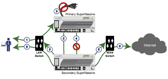
The following figure shows the sequence of events that occurs during a failover in a Stateful High Availability network.
1. A PC user connects to the network, and the Primary SonicWALL SuperMassive creates a session for the user.
2. The Primary appliance synchronizes with the Secondary appliance. The Secondary now has all of the user’s session information.
3. The power is unplugged from the Primary appliance and it goes down.
4. The Secondary unit does not receive heartbeat messages from the Primary appliance and switches from Idle to Active mode.
5. The Secondary appliance begins to send gratuitous ARP messages to the LAN and WAN switches using the same Virtual MAC address and IP address as the Primary appliance. No routing updates are necessary for downstream or upstream network devices.
6. When the PC user attempts to access a Web page, the Secondary appliance has all of the user’s session information and is able to continue the user’s session without interruption.
With Active/Active DPI enabled on a Stateful HA pair, these DPI services are processed on the idle firewall of an HA pair concurrently with the processing of firewall, NAT, and other modules on the active firewall. The following DPI services are affected:
• Intrusion Prevention Service (IPS)
• Gateway Anti-Virus (GAV)
• Gateway Anti-Spyware
• App Rules
Active/Active DPI taps into the unused CPU cycles available in the idle unit, but the traffic still arrives and leaves through the active unit. The idle unit only sees the network traffic offloaded by the active unit, and processing of all modules other than DPI services is restricted to the active unit.
Active/Idle and Active/Active DPI HA Prerequisites
This section describes the requirements for registering your SonicWALL appliance and licensing the SonicWALL High Availability features.
SonicWALL SuperMassive requires the following interface link speeds for each designated HA interface:
• HA Control Interface—Must be a 1GB interface:
X6 to X21 interfaces at 1 Gbps - Full Duplex
• HA Data Interface—Must be a 10GB interface:
X0 to X5 interfaces at 10 Gbps - Full Duplex
• Active/Active DPI Interface—Must be a 10GB interface:
X0 to X5 interfaces at 10 Gbps - Full Duplex
• Active/Active Cluster Link—Must be a 1GB interface:
X6 to X21 interfaces at 1 Gbps - Full Duplex
See the following sections:
• Configuring Active/Idle High Availability
• Configuring Active/Active DPI High Availability
• Physically Connecting Your Appliances
• Configuring Network DHCP and Interface Settings
• Registering and Associating Appliances on MySonicWALL
• Licensing High Availability Features
Configuring Active/Idle High Availability
This section provides a high level task list for getting the Active/Active Clustering and other High Availability features up and running:
1. Preform the tasks described in Active/Idle and Active/Active DPI HA Prerequisites, including registering and associating the appliances on MySonicWALL and licensing the high availability features.
2. Physically connect the designated HA ports from the Primary to the Secondary HA unit.
3. Power down all the units except the unit that is to be designated as the Primary unit
4. Login to the Primary unit, leaving other units down.
5. On the Network > DHCP Server page, disable the DHCP server and delete all DHCP server lease scopes.
6. Configure IP addresses for the desired interfaces on the Network > Interfaces page.
7. On the High Availability > Settings page, select Active/Idle.
8. Enter the serial numbers of other units in the Active/Idle HA pair.
9. Click Apply.
10.Configure Virtual Group IP addresses on the Network > Interfaces page.
Note Default NAT policies will be created automatically, so there is no need to configure NAT policies for Virtual Groups in the Network > NAT Policies page
11.Configure settings in the High Availability > Advanced page.
12.Start up the other units in the Active/Idle HA pair.
13.Configure per-unit IP addresses in the High Availability > Monitoring page.
Note Per-unit IP addresses (HA monitoring IP addresses) are required for all the units in the cluster either on Primary LAN or on Primary WAN Interfaces.
14.Login to each unit using the per-unit IP address, and click Register and synchronize licenses with the MySonicWALL Licensing server.
15.Enable Stateful Synchronization.
Configuring Active/Active DPI High Availability
This section provides a high level task list for getting the Active/Active Clustering and other High Availability features up and running:
1. Preform the tasks described in Active/Idle and Active/Active DPI HA Prerequisites, including registering and associating the appliances on MySonicWALL and licensing the high availability features.
2. Physically connect the designated HA ports from the Primary to the Secondary HA unit.
3. Physically connect an additional interface between the two appliances in each HA pair if you plan to enable Active/Active DPI. The interface must be the same number on both appliances. For example, connect X4 on the Primary unit to X4 on the Secondary.
4. Optionally, for port redundancy for Active/Active DPI ports, physically connect a second interface between the two appliances in each HA pair. This interface will take over transferring data between the two units during Active/Active DPI processing if the first Active/Active DPI Interface has a fault.
5. Physically connect the LAN and WAN ports of all units to the appropriate switches.
6. Optionally, if you plan to use redundant ports for the LAN/WAN ports, connect the redundant ports to the appropriate switches.
7. Power down all the units except the unit that is to be designated as the Primary unit in Cluster Node 1.
8. Login to the Primary unit in Cluster Node 1, leaving other units down.
9. On the Network > DHCP Server page, disable the DHCP server and delete all DHCP server lease scopes.
10.Configure IP addresses for the desired interfaces on the Network > Interfaces page.
11.Select Active/Active DPI on the High Availability > Settings page.
12.Enter the serial numbers of other units in the Active/Active cluster.
13.Enter the Cluster Node owner/standby rankings for each Virtual Group.
14.Click Apply.
15.Configure Virtual Group IP addresses on the Network > Interfaces page.
Note Default NAT policies will be created automatically, so there is no need to configure NAT policies for Virtual Groups in the Network > NAT Policies page
16.Configure settings in the High Availability > Advanced page.
17.Start up the other units in the Active/Active cluster.
18.Configure per-unit IP addresses in the High Availability > Monitoring page.
Note Per-unit IP addresses (HA monitoring IP addresses) are required for all the units in the cluster either on Primary LAN or on Primary WAN Interfaces.
19.Login to each unit using the per-unit IP address, and click Register and synchronize licenses with the MySonicWALL Licensing server.
20.Enable Stateful Synchronization.
21.Enable Active/Active DPI and configure the appropriate interface as the Active/Active DPI Interface.
22.If a second interface is physically connected, configure it as the Active/Active DPI Interface 2 for Active/Active DPI.
Active/Active Clustering Overview
This section provides an introduction to the Active/Active Clustering feature. With Active/Active Clustering, you can assign certain traffic flows to each node in the cluster, providing load sharing in addition to redundancy, and supporting a much higher throughput without a single point of failure.
A typical recommended setup includes four firewalls of the same SonicWALL model configured as two Cluster Nodes, where each node consists of one Stateful HA pair. For larger deployments, the cluster can include eight firewalls, configured as four Cluster Nodes (or HA pairs). Within each Cluster Node, Stateful HA keeps the dynamic state synchronized for seamless failover with zero loss of data on a single point of failure. Stateful HA is not required, but is highly recommended for best performance during failover.
Load sharing is accomplished by configuring different Cluster Nodes as different gateways in your network. Typically this is handled by another device downstream (closer to the LAN devices) from the Active/Active Cluster, such as a DHCP server or a router.
A Cluster Node can also be a single firewall, allowing an Active/Active cluster setup to be built using two firewalls. In case of a fault condition on one of the firewalls in this deployment, the failover is not stateful since neither firewall in the Cluster Node has an HA Secondary.
Redundancy is achieved at several levels with Active/Active Clustering:
• The cluster provides redundant Cluster Nodes, each of which can handle the traffic flows of any other Cluster Node, if a failure occurs.
• The Cluster Node consists of a Stateful HA pair, in which the Secondary firewall can assume the duties of the Primary unit in case of failure.
• Port redundancy, in which an unused port is assigned as a secondary to another port, provides protection at the interface level without requiring failover to another firewall or node.
• Active/Active DPI can be enabled, providing increased throughput within each Cluster Node.
This section contains the following subsections:
• Caveats
• Feature Support Information with Active/Active Clustering
The benefits of Active/Active Clustering include the following:
• All the firewalls in the cluster are utilized to derive maximum throughput
• Can run in conjunction with Active/Active DPI to perform concurrent processing of IPS, GAV, Anti-Spyware, and App Rules services, which are the most processor intensive, on the idle firewall in each HA pair while the active firewall performs other processing
• Load sharing is supported by allowing the assignment of particular traffic flows to each node in the cluster
• All nodes in the cluster provide redundancy for the other nodes, handling traffic as needed if other nodes go down
• Interface redundancy provides secondary for traffic flow without requiring failover
• Both Full Mesh and non-Full Mesh deployments are supported
There are several important concepts that are introduced for Active/Active Clustering. See the following sections for descriptions of these new concepts and changes to existing functionality:
• About Redundant Ports and Redundant Switches
• About High Availability Monitoring
An Active/Active Cluster is formed by a collection of Cluster Nodes. A Cluster Node can consist of a Stateful HA pair, a Stateless HA pair or a single standalone unit. Dynamic state synchronization is only available in a Cluster Node if it is a Stateful HA pair. The traditional SonicWALL High Availability protocol or Stateful HA protocol is used for communication within the Cluster Node, between the units in the HA pair.
When a Cluster Node is a Stateful HA pair, Active/Active DPI can be enabled within the Cluster Node for higher performance.
All devices in the Cluster must be of same product model and be running the same firmware version.
Within the cluster, all units are connected and communicating with each other. For physical connectivity, the designated HA ports of all the units in the cluster must be connected to the same Layer 2 network. For communication between Cluster Nodes, a new protocol called SonicWALL Virtual Router Redundancy Protocol (SVRRP) is used. Cluster Node management and monitoring state messages are sent using SVRRP.
All Cluster Nodes share the same configuration, which is synchronized by the Master Node. The Master Node is also responsible for synchronizing firmware to the other nodes in the cluster. The HA port connection is used to synchronize configuration and firmware updates.
Dynamic state is not synchronized across Cluster Nodes, but only within a Cluster Node. When a Cluster Node contains an HA pair, Stateful HA can be enabled within that Cluster Node, with the advantages of dynamic state synchronization and stateful failover as needed. In the event of the failure of an entire Cluster Node, the failover will be stateless. This means that pre-existing network connections must be rebuilt. For example, Telnet and FTP sessions must be re-established and VPN tunnels must be renegotiated. The About Failover provides more information about how failover works.
The maximum number of Cluster Nodes in a cluster is currently limited to four. If each Cluster Node is an HA pair, the cluster will include eight firewalls.
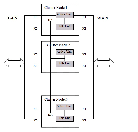
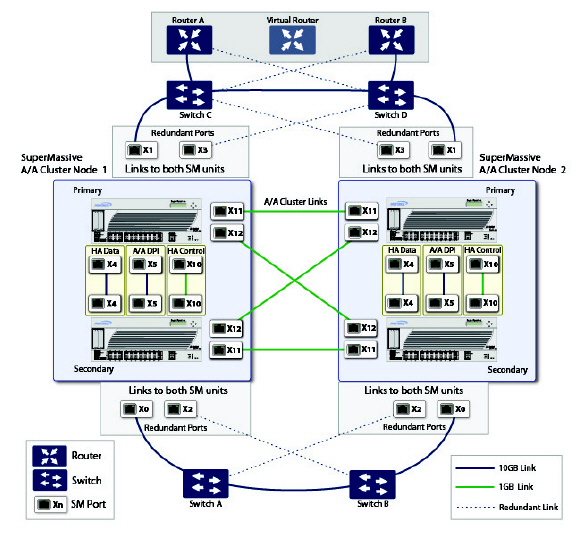
Figure 51:10 illustrates the Active/Active Clustering topology.
Figure 51:10 Active/Active Clustering Topology
Actions Allowed Within the Cluster
The types of administrative actions that are allowed differ based on the state of the firewall in the cluster. All actions are allowed for admin users with appropriate privileges on the active firewall of the Master Node, including all configuration actions. A subset of actions are allowed on the active firewall of Non-Master nodes, and even fewer actions are allowed on firewalls in the idle state. Table 4 lists the allowed actions for active firewalls of Non-Master nodes and idle firewalls in the cluster.
Table 4 Administrative Actions Allowed
|
Active/Active Clustering also introduces the concept of Virtual Groups. Currently, a maximum of four Virtual Groups are supported.
A Virtual Group is a collection of virtual IP addresses for all the configured interfaces in the cluster configuration (unused/unassigned interfaces do not have virtual IP addresses). When Active/Active Clustering is enabled for the first time, the configured IP addresses for the interfaces on that firewall are converted to virtual IP addresses for Virtual Group 1. Thus, Virtual Group 1 will include virtual IP addresses for X0, X1, and any other interfaces which are configured and assigned to a zone.
A Virtual Group can also be thought of as a logical group of traffic flows within a failover context, in that the logical group of traffic flows can failover from one node to another depending upon the fault conditions encountered. Each Virtual Group has one Cluster Node acting as the owner and one or more Cluster Nodes acting as standby. A Virtual Group is only owned by one Cluster Node at a time, and that node becomes the owner of all the virtual IP addresses associated with that Virtual Group. The owner of Virtual Group 1 is designated as the Master Node, and is responsible for synchronizing configuration and firmware to the other nodes in the cluster. If the owner node for a Virtual Group encounters a fault condition, one of the standby nodes will become the owner.
As part of the configuration for Active/Active Clustering, the serial numbers of other firewalls in the cluster are entered into the SonicOS management interface, and a ranking number for the standby order is assigned to each. When the Active/Active Clustering configuration is applied, up to three additional Virtual Groups are created, corresponding to the additional Cluster Nodes added, but virtual IP addresses are not created for these Virtual Groups. You need to configure these virtual IP addresses on the Network > Interfaces page.
There are two factors in determining Virtual Group ownership (which Cluster Node will own which Virtual Group):
• Rank of the Cluster Node – The rank is configured in the SonicOS management interface to specify the priority of each node for taking over the ownership of a Virtual Group.
• Virtual Group Link Weight of the Cluster Nodes – This is the number of interfaces in the Virtual Group that are up and have a configured virtual IP address.
When more than two Cluster Nodes are configured in a cluster, these factors determine the Cluster Node that is best able to take ownership of the Virtual Group. In a cluster with two Cluster Nodes, one of which has a fault, naturally the other will take ownership.
SVRRP is used to communicate Virtual Group link status and ownership status to all Cluster Nodes in the cluster.
The owner of Virtual Group 1 is designated as the Master Node. Configuration changes and firmware updates are only allowed on the Master Node, which uses SVRRP to synchronize the configuration and firmware to all the nodes in the cluster. On a particular interface, virtual IP addresses for Virtual Group 1 must be configured before other Virtual Groups can be configured.
Load Sharing and Multiple Gateway Support
The traffic for the Virtual Group is processed only by the owner node. A packet arriving on a Virtual Group will leave the firewall on the same Virtual Group. In a typical configuration, each Cluster Node owns a Virtual Group, and therefore processes traffic corresponding to one Virtual Group.
This Virtual Group functionality supports a multiple gateway model with redundancy. In a deployment with two Cluster Nodes, the X0 Virtual Group 1 IP address can be one gateway and the X0 Virtual Group 2 IP address can be another gateway. It is up to the network administrator to determine how the traffic is allocated to each gateway. For example, you could use a smart DHCP server which distributes the gateway allocation to the PCs on the directly connected client network, or you could use policy based routes on a downstream router.
When Active/Active Clustering is enabled, the SonicOS internal DHCP server is turned off and cannot be enabled. Networks needing a DHCP server can use an external DHCP server which is aware of the multiple gateways, so that the gateway allocation can be distributed.
Note When Active/Active Clustering is enabled, the SonicOS internal DHCP server is turned off.
Effect on Related Configuration Pages
When Active/Active Clustering is initially enabled, the existing IP addresses for all configured interfaces are automatically converted to virtual IP addresses for Virtual Group 1. When Virtual Group 1 or any Virtual Group is created, default interface objects are created for virtual IP addresses with appropriate names, such as “Virtual Group 1” or “Virtual Group 2”. The same interface can have multiple virtual IP addresses, one for each Virtual Group that is configured. You can view these virtual IP addresses in the Network > Interfaces page.
Note All Cluster Nodes in the Active/Active cluster share the same configuration
A virtual MAC address is associated with each virtual IP address on an interface and is generated automatically by Sonic OS. The virtual MAC address is created in the format 00-17-c5-6a-XX-YY, where XX is the interface number such as “03” for port X3, and YY is the internal group number such as “00” for Virtual Group 1, or “01” for Virtual Group 2.
Note The Active/Active virtual MAC address is different from the High Availability virtual MAC address. The High Availability virtual MAC address functionality is not supported when Active/Active Clustering is enabled.
NAT policies are automatically created for the affected interface objects of each Virtual Group. These NAT policies extend existing NAT policies for particular interfaces to the corresponding virtual interfaces. You can view these NAT policies in the Network > NAT Policies page. Additional NAT policies can be configured as needed and can be made specific to a Virtual Group if desired.
After Active/Active Clustering is enabled, you must select the Virtual Group number during configuration when adding a VPN policy.
For communication between Cluster Nodes in an Active/Active cluster, a new protocol called SonicWALL Virtual Router Redundancy Protocol (SVRRP) is used. Cluster Node management and monitoring state messages are sent using SVRRP over the HA port connection.
SVRRP is also used to synchronize configuration changes, firmware updates, and signature updates from the Master Node to all nodes in the cluster. In each Cluster Node, only the active unit processes the SVRRP messages.
In the case of failure of the HA port connection, SVRRP heartbeat messages are sent on the X0 interface. However, while the HA port connection is down, configuration is not synchronized. Firmware or signature updates, changes to policies, and other configuration changes cannot be synchronized to other Cluster Nodes until the HA port connection is fixed.
About Redundant Ports and Redundant Switches
Redundant ports can be used along with Active/Active Clustering. If one port should have a fault, the traffic is seamlessly handled through the redundant port without causing an HA or Active/Active failover. A Redundant Port field in the Network > Interfaces > Edit Interface page becomes available when Active/Active Clustering is enabled.
When configuring a redundant port, the interface must be unused; that is, not assigned to any zone. The two ports must be physically connected to the same switch, or preferably, to redundant switches in the network.
Note Because all Cluster Nodes shares the same configuration, each node must have the same redundant ports configured and connected to the same switch(es).
While all Cluster Nodes are up and processing traffic normally, redundant ports remain idle and are ready for use if the partner port goes down for any reason. If one Cluster Node goes down, causing an Active/Active failover, the redundant port on the remaining Cluster Node is put to use immediately to handle the traffic for the Virtual Group that was owned by the failed node. This provides load sharing.
For example, say we have a deployment in which Virtual Group 1 is owned by Cluster Node 1 and Virtual Group 2 is owned by Cluster Node 2. The Cluster Nodes are configured with redundant ports, X3 and X4. No traffic is sent on X4 while all nodes are functioning properly. If Cluster Node 2 goes down, Virtual Group 2 is now also owned by Cluster Node 1. At this point, the redundant port X4 begins to be used for load sharing. Virtual Group 1 traffic is sent on X3, while Virtual Group 2 traffic is sent on X4. In a larger deployment, if Cluster Node 1 owns three or four Virtual Groups, traffic is distributed among the redundant ports – traffic for Virtual Groups 1 & 3 is sent on X3, while traffic for Virtual Groups 2 & 4 is sent on X4.
When a redundant switch is configured, SonicWALL recommends using a redundant port to connect to it. While it is possible to connect a redundant switch without using a redundant port, this involves complex configuration using probes. A redundant switch can be deployed anywhere in the network depending on the need for high availability. For example, a redundant switch might be deployed on the WAN side if traffic passing through it is business-critical.
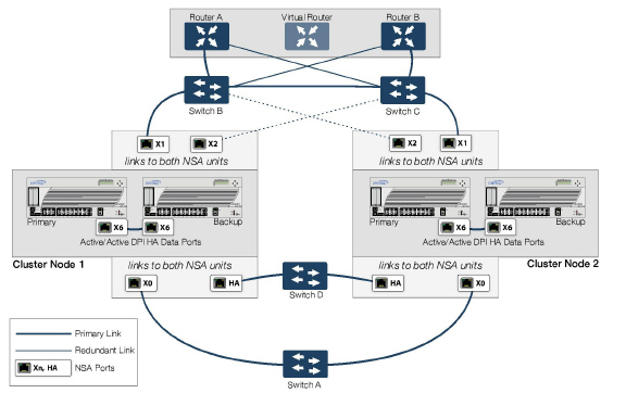
Figure 51:11 shows a diagram of a deployment that includes redundant routers, switches, and ports on the WAN side, but is not a Full Mesh deployment because the LAN side does not use redundancy. Update network diagram: SuperMassive network diagram.
Figure 51:11 WAN Side Redundancy
Full Mesh is not required when deploying redundant ports or switches, but a Full Mesh deployment includes them. A Full Mesh deployment uses redundant ports on each of the main traffic ports (LAN, WAN, etc.), and uses redundant upstream routers in addition to redundant switches.
For more information about Full Mesh deployments, see the Active/Active Clustering Full Mesh Deployment Technote.
There are two types of failover that can occur when Active/Active Clustering is enabled:
• High Availability failover – Within an HA pair, the Secondary unit takes over for the Primary. If Stateful HA is enabled for the pair, the failover occurs without interruption to network connections.
• Active/Active failover – If all the units in the owner node for a Virtual Group encounter a fault condition, then the standby node for the Virtual Group takes over the Virtual Group ownership. Active/Active failover transfers ownership of a Virtual Group from one Cluster Node to another. The Cluster Node that becomes the Virtual Group owner also becomes the owner of all the virtual IP addresses associated with the Virtual Group and starts using the corresponding virtual MAC addresses.
Active/Active failover is stateless, meaning that network connections are reset and VPN tunnels must be renegotiated. Layer 2 broadcasts inform the network devices of the change in topology as the Cluster Node which is the new owner of a Virtual Group generates ARP requests with the virtual MACs for the newly owned virtual IP addresses. This greatly simplifies the failover process as only the connected switches need to update their learning tables. All other network devices continue to use the same virtual MAC addresses and do not need to update their ARP tables, because the mapping between the virtual IP addresses and virtual MAC addresses is not broken.
When both High Availability failover and Active/Active failover are possible, HA failover is given precedence over Active/Active failover for the following reasons:
• HA failover can be stateful, whereas Active/Active failover is stateless.
• The idle firewall in an HA pair is lightly loaded and has resources available for taking over the necessary processing, although it may already be handling DPI traffic if Active/Active DPI is enabled. The alternative Cluster Node might already be processing traffic comparable in amount to the failed unit, and could become overloaded after failover.
Active/Active failover always operates in Active/Active preempt mode. Preempt mode means that, after failover between two Cluster Nodes, the original owner node for the Virtual Group will seize the active role from the standby node after the owner node has been restored to a verified operational state. The original owner will have a higher priority for a Virtual Group due to its higher ranking if all virtual IP interfaces are up and the link weight is the same between the two Cluster Nodes.
In addition to the two types of failover, the following feature provides protection against a single point of failure:
• Port Redundancy – Although technically not a failover, a redundant port provides secondary by handling all the traffic if its partner has a fault.
Active/Active Clustering can be enabled with or without enabling Active/Active DPI, just as Active/Active DPI can be enabled with or without enabling Active/Active Clustering. For increased performance in an Active/Active cluster, enabling Active/Active DPI is recommended, as it utilizes the idle firewall in the HA pair for Deep Packet Inspection (DPI) processing.
To use the Active/Active DPI feature, the administrator must configure an additional interface as the Active/Active DPI Interface. If you choose to make X5 the Active/Active DPI Interface, you must physically connect X5 on the active unit to X5 on the idle unit in the HA pair. Certain packet flows on the active unit are selected and offloaded to the idle unit on the Active/Active DPI Interface. DPI is performed on the idle unit and then the results are returned to the active unit over the same interface. The remaining processing is performed on the active unit.
After enabling Stateful Synchronization on the appliances in the HA pair and connecting and configuring the Active/Active DPI Interface(s), you can enable Active/Active DPI on the High Availability > Settings page.
About High Availability Monitoring
When Active/Active Clustering is enabled, HA monitoring configuration is supported for the HA pair in each Cluster Node. The HA monitoring features are consistent with previous versions. HA monitoring can be configured for both physical/link monitoring and logical/probe monitoring. After logging into the Master Node, monitoring configuration needs to be added on a per Node basis from the High Availability > Monitoring page.
Note The High Availability > Monitoring page applies only to the HA pair that you are logged into, not to the entire cluster.
Physical interface monitoring enables link detection for the monitored interfaces. The link is sensed at the physical layer to determine link viability.
When physical interface monitoring is enabled, with or without logical monitoring enabled, HA failover takes precedence over Active/Active failover. If a link fails or a port is disconnected on the active unit, the idle unit in the HA pair will become active.
Note For interfaces with configured virtual IP addresses, Active/Active physical monitoring is implicit and is used to calculate the Virtual Group Link Weight. Physical monitoring cannot be disabled for these interfaces. This is different from HA monitoring.
Logical monitoring involves configuring the SonicWALL to monitor a reliable device on one or more of the connected networks. Failure to periodically communicate with the device by the active unit in the HA pair will trigger a failover to the idle unit. If neither unit in the HA pair can connect to the device, the problem is assumed to be with the device and no failover will occur.
If both physical monitoring and logical monitoring are disabled, Active/Active failover will occur on link failure or port disconnect.
The Primary and Secondary IP addresses configured on the High Availability > Monitoring page can be configured on LAN or WAN interfaces, and are used for multiple purposes:
• As independent management addresses for each unit, regardless of the Active or Idle status of the unit (supported on all physical interfaces)
• To allow synchronization of licenses between the idle unit and the SonicWALL licensing server
• As the source IP addresses for the probe pings sent out during logical monitoring
Configuring monitoring IP addresses for both units in the HA pair allows you to log in to each unit independently for management purposes. Note that non-management traffic is ignored if it is sent to one of the monitoring IP addresses. The Primary and Secondary SonicWALL SuperMassive’s unique LAN IP addresses cannot act as an active gateway; all systems connected to the internal LAN will need to use a virtual LAN IP address as their gateway.
Note When HA Monitoring/Management IP addresses are configured only on WAN interfaces, they need to be configured on all the WAN interfaces for which a Virtual IP address has been configured.
The management IP address of the Secondary unit is used to allow license synchronization with the SonicWALL licensing server, which handles licensing on a per-appliance basis (not per-HA pair). Even if the idle unit was already registered on MySonicWALL before creating the HA association, you must use the link on the System > Licenses page to connect to the SonicWALL server while accessing the Secondary appliance through its management IP address. This allows synchronization of licenses (such as the Active/Active Clustering or the Stateful HA license) between the idle unit and the SonicWALL licensing server.
When using logical monitoring, the HA pair will ping the specified Logical Probe IP address target from the Primary as well as from the Secondary SonicWALL. The IP address set in the Primary IP Address or Secondary IP Address field is used as the source IP address for the ping. If both units can successfully ping the target, no failover occurs. If both cannot successfully ping the target, no failover occurs, as the SonicWALLs will assume that the problem is with the target, and not the SonicWALLs. But, if one SonicWALL can ping the target but the other SonicWALL cannot, the HA pair will failover to the SonicWALL that can ping the target.
The configuration tasks on the High Availability > Monitoring page are performed on the Primary unit and then are automatically synchronized to the Secondary.
Active/Active Clustering Full Mesh configuration is an enhancement to the Active/Active Clustering configuration option and provides the highest level of availability possible with high performance. Full Mesh deployments provide a very high level of availability for the network, because all devices have one or more redundant partners, including routers, switches, and security appliances. Every device is wired twice to the connected devices, so that no single point of failure exists in the entire network. For example, every SonicWALL firewall uses redundant ports to connect twice to each networking device.
Note Full Mesh deployments require that Port Redundancy is enabled and implemented.
Figure 51:12 shows a diagram of a Four-unit Full Mesh deployment.
Figure 51:12 Four-Unit Full Mesh Deployment
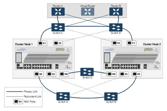
You can also configure a Full Mesh deployment using only two firewalls, one per Cluster Node. Figure 51:13 shows a 2-unit Full Mesh deployment diagram.
Figure 51:13 Two-Unit Full Mesh Deployment
For more information about Full Mesh deployments, see the Active/Active Clustering Full Mesh Deployment Technote, available on http://www.sonicwall.com/us/Support.html
The following sections provides feature support information about Active/Active Clustering:
• WAN Load Balancing Compatibility
• Routing Topology and Protocol Compatibility
When Active/Active Clustering is enabled, only static IP addresses can be used on the WAN.
The following features are not supported when Active/Active Clustering is enabled:
• DHCP Server
• L3 Transparent Mode
• L2 Bridging / L2 Transparent Mode
• Dynamic DNS
• Wire Mode
The following features are only supported on Virtual Group 1:
• SonicWALL GVC
• SonicOS SSL VPN
• IP Helper
The Active/Active Clustering feature is not backward compatible. When upgrading to SonicOS from a previous release that did not support Active/Active Clustering, it is highly recommended that you disable High Availability before exporting the preferences from an HA pair running a previous version of SonicOS. The preferences can then be imported without potential conflicts after upgrading.
There are two points to consider when using SonicWALL SonicPoints together with Active/Active Clustering:
1. SonicPoints only communicate with the Master node for downloading firmware and other aspects of operation.
2. SonicPoints need access to an independent DCHP server. SonicPoints require a DHCP server to provide IP addresses to wireless clients, but the embedded SonicOS DHCP server is automatically disabled when Active/Active Clustering is enabled.
WAN Load Balancing Compatibility
When WAN Load Balancing (WLB) is enabled in an Active/Active Cluster, the same WLB interface configuration is used for all nodes in the cluster.
A WAN interface failure can trigger either a WLB failover, an HA pair failover, or an Active/Active failover to another Cluster Node, depending on the following:
• WAN goes down logically due to WLB probe failure – WLB failover
• Physical WAN goes down while Physical Monitoring is enabled – HA pair failover
• Physical WAN goes down while Physical Monitoring is not enabled – Active/Active failover
Routing Topology and Protocol Compatibility
This section describes the current limitations and special requirements for Active/Active Clustering configurations with regard to routing topology and routing protocols.
Layer-2 Bridge Support
Layer-2 Bridged interfaces are not supported in a cluster configuration.
OSPF Support
OSPF is supported with Active/Active Clustering. When enabled, OSPF runs on the OSPF-enabled interfaces of each active Cluster Node. From a routing perspective, all Cluster Nodes appear as parallel routers, each with the virtual IP address of the Cluster Node's interface. In general, any network advertised by one node will be advertised by all other nodes.
The OSPF router-ID of each Cluster Node must be unique and will be derived from the router-ID configured on the Master node as follows:
• If the user enters 0 or 0.0.0.0 for the router-ID in the OSPF configuration, each node’s router-ID will be assigned the node’s X0 virtual IP address.
• If the user enters any value other than 0 or 0.0.0.0 for the router-ID, each node will be assigned a router-ID with consecutive values incremented by one for each node. For example, in a 4-node cluster, if the router-ID 10.0.0.1 was configured on the Master node, the router-ID’s assigned would be as follows:
– Node 1: 10.0.0.1
– Node 2: 10.0.0.2
– Node 3: 10.0.0.3
– Node 4: 10.0.0.4
RIP Support
RIP is supported, and like OSPF, will run on the RIP-enabled interfaces of each Cluster Node. From a routing perspective, all Cluster Nodes will appear as parallel routers with the virtual IP address of the Cluster Node’s interface. In general, any network advertised by one node will be advertised by all other nodes.
BGP Support
BGP is supported in clusters, and will also appear as parallel BGP routers using the virtual IP address of the Cluster Node’s interface. As with OSPF and RIP, configuration changes made on the Master node will be applied to all other Cluster Nodes. In the case of BGP, where configuration may only be applied through the CLI, the configuration is distributed when the running configuration is saved with the write file CLI command.
Asymmetric Routing Issues In Cluster Configurations
Any network appliance that performs deep packet inspection or stateful firewall activity must “see” all packets associated with a packet flow. This is in contrast to traditional IP routing in which each packet in a flow may technically be forwarded along a different path as long as it arrives at it’s intended destination – the intervening routers do not have to see every packet. Today’s routers do attempt to forward packets with a consistent next-hop for each packet flow, but this applies only to packets forwarded in one direction. Routers make no attempt to direct return traffic to the originating router. This IP routing behavior presents problems for a firewall cluster because the set of Cluster Nodes all provide a path to the same networks. Routers forwarding packets to networks through the cluster may choose any of the Cluster Nodes as the next-hop. The result is asymmetric routing, in which the flow of packets in one direction go through a node different than that used for the return path. This will cause traffic to be dropped by one or both Cluster Nodes since neither is “seeing” all of the traffic from the flow.
There are two ways to avoid asymmetric routing paths:
1. Engineer all networks and routers connected to the cluster such that packet forwarding will always result in symmetric paths in respect to the virtual IP addresses used in the cluster.
2. Create a full mesh configuration of NAT rules in the cluster so every interface-pair has a NAT rule which replaces the source IP address in the packet with the virtual IP of the egress interface. These rules should be the same as the default rules created between trusted and non-trusted zoned interfaces. When the full mesh NAT rules are in place, the forward and reverse paths of flows transiting the cluster will always flow through the same Cluster Node (or the current owner of the Cluster Node’s primary virtual IP addresses).
Configuring Active/Active Clustering and HA
Note Before performing the procedures described in this section, ensure that you have completed the prerequisites described in Active/Idle and Active/Active DPI HA Prerequisites.
Active/Active Clustering configuration can include configuring Virtual Group IDs and redundant ports. Procedures are provided in this section for both of these tasks within the High Availability > Settings section.
There are four High Availability pages in the SonicOS management interface. Of these, two have configurable settings that pertain to Active/Active Clustering, one displays status for both the cluster and the HA pair to which you are logged in, and one pertains only to configuration for the local HA pair. The latter is the High Availability > Monitoring page. This document describes the configuration options for all High Availability settings, whether they pertain to Active/Active Clustering or only to the HA pair.
See the following sections:
• High Availability > Settings
• High Availability > Advanced
• High Availability > Monitoring
The following sections describe the High Availability > Status page:
• Active/Idle High Availability Status
• Active/Active High Availability Status
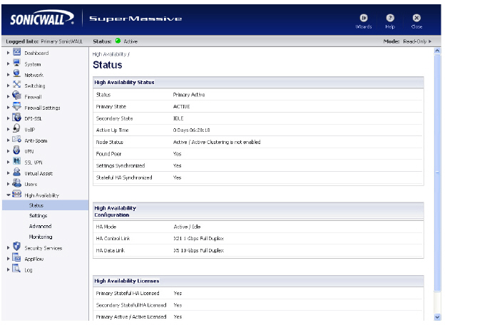
Active/Idle High Availability Status
The High Availability Status table on the High Availability > Status page displays the current status of the HA Pair. If the Primary SonicWALL is Active, the first line in the table indicates that the Primary SonicWALL is currently Active.
It is also possible to check the status of the Secondary SonicWALL by logging into the unique LAN IP address of the Secondary SonicWALL. If the Primary SonicWALL is operating normally, the status indicates that the Secondary SonicWALL is currently Idle. If the Secondary has taken over for the Primary, the status table indicates that the Secondary is currently Active.
In the event of a failure in the Primary SonicWALL, you can access the management interface of the Secondary SonicWALL at the Primary SonicWALL virtual LAN IP address or at the Secondary SonicWALL LAN IP address. When the Primary SonicWALL restarts after a failure, it is accessible using the unique IP address created on the High Availability > Monitoring page. If preempt mode is enabled, the Primary SonicWALL becomes the Active firewall and the Secondary firewall returns to Idle status.
The table displays the following information:
High Availability Status
• Status – Indicates the HA state of the Primary SonicWALL SuperMassive. The possible values are:
– Primary Active – Indicates that the Primary HA appliance is in the ACTIVE state.
– Primary Idle – Indicates that this appliance is in the IDLE state.
– Primary Disabled – Indicates that High Availability has not been enabled in the management interface of this appliance.
– Primary not in a steady state – Indicates that HA is enabled and the appliance is neither in the ACTIVE nor the IDLE state.
• Primary State - Indicates the current state of the Primary appliance as a member of an HA Pair. The Primary State field is displayed on both the Primary and the Secondary appliances. The possible values are:
– ACTIVE – Indicates that the Primary unit is handling all the network traffic except management/monitoring/licensing traffic destined to the IDLE unit.
– IDLE – Indicates that the Primary unit is passive and is ready to take over on a failover.
– ELECTION – Indicates that the Primary and Secondary units are negotiating which should be the ACTIVE unit.
– SYNC – Indicates that the Primary unit is synchronizing settings or firmware to the Secondary.
– ERROR – Indicates that the Primary unit has reached an error condition.
– REBOOT – Indicates that the Primary unit is rebooting.
– NONE – When viewed on the Primary unit, NONE indicates that HA is not enabled on the Primary. When viewed on the Secondary unit, NONE indicates that the Secondary unit is not receiving heartbeats from the Primary unit.
• Secondary State - Indicates the current state of the Secondary appliance as a member of an HA Pair. The Secondary State field is displayed on both the Primary and the Secondary appliances. The possible values are:
– ACTIVE – Indicates that the Secondary unit is handling all the network traffic except management/monitoring/licensing traffic destined to the IDLE unit.
– IDLE – Indicates that the Secondary unit is passive and is ready to take over on a failover.
– ELECTION – Indicates that the Secondary and Primary units are negotiating which should be the ACTIVE unit.
– SYNC – Indicates that the Secondary unit is synchronizing settings or firmware to the Primary.
– ERROR – Indicates that the Secondary unit has reached an error condition.
– REBOOT – Indicates that the Secondary unit is rebooting.
– NONE – When viewed on the Secondary unit, NONE indicates that HA is not enabled on the Secondary. When viewed on the Primary unit, NONE indicates that the Primary unit is not receiving heartbeats from the Secondary unit.
• Active Up Time - Indicates how long the current Active firewall has been Active, since it last became Active. This line only displays when High Availability is enabled. If failure of the Primary SonicWALL occurs, the Secondary SonicWALL assumes the Primary SonicWALL LAN and WAN IP addresses. There are three main methods to check the status of the High Availability Pair: the High Availability Status window, Email Alerts and View Log. These methods are described in the following sections.
• Node Status - Indicates if Active / Active Clustering is enabled or is not enabled.
• Found Peer - Indicates if the Primary unit has discovered the Secondary unit. Possible values are Yes and No.
• Settings Synchronized - Indicates if HA settings are synchronized between the Primary and Secondary units. Possible values are Yes and No.
• Stateful HA Synchronized - Indicates if stateful synchronization settings are synchronized between the Primary and Secondary units. Possible values are Yes and No.
High Availability Configuration
• HA Mode - One method to determine which SonicWALL is Active is to check the HA Settings Status indicator on the High Availability > Settings page. If the Primary SonicWALL is Active, the first line in the page indicates that the Primary SonicWALL is currently Active. It is also possible to check the status of the Secondary SonicWALL by logging into the LAN IP address of the Secondary SonicWALL. If the Primary SonicWALL is operating normally, the status indicates that the Secondary SonicWALL is currently Idle. If the Secondary has taken over for the Primary, the status indicates that the Secondary is currently Active. In the event of a failure in the Primary SonicWALL, you can access the management interface of the Secondary SonicWALL at the Primary SonicWALL LAN IP address or at the Secondary SonicWALL LAN IP address. When the Primary SonicWALL restarts after a failure, it is accessible using the third IP address created during configuration. If preempt mode is enabled, the Primary SonicWALL becomes the Active firewall and the Secondary firewall returns to Idle status.
• HA Control Link – Indicates the port, speed, and duplex settings of the HA link, such as HA 1000 Mbps full-duplex, when two SonicWALL SuperMassives are connected over their specified HA interfaces. When High Availability is not enabled, the field displays Disabled.
• HA Data Link – Indicates the port, speed, and duplex settings of the HA link, such as HA 1000 Mbps full-duplex, when two SonicWALL SuperMassives are connected over their specified HA interfaces. When High Availability is not enabled, the field displays Disabled.
High Availability Licenses
• Primary Stateful HA Licensed - Indicates if the Primary appliance has a stateful HA license. Possible values are Yes or No.
• Secondary Stateful HA Licensed - Indicates if the Secondary appliance has a stateful HA license. Possible values are Yes or No. Note that the Stateful HA license is shared with the Primary, but that you must access mysonicwall.com while logged into the LAN management IP address of the Secondary unit in order to synchronize with the SonicWALL licensing server.
• Primary Active / Active Licensed - Indicates if the Primary appliance has a Active / Active license. Possible values are Yes or No.
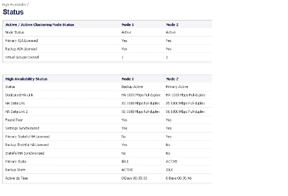
Active/Active High Availability Status
The High Availability > Status page provides status for the entire Active/Active cluster and for each Cluster Node in the deployment. The status for the Active/Active cluster is displayed in the upper table, and status for the each Cluster Node is displayed in the lower table.
Figure 51:14 High Availability > Status Page
For additional information on High Availability status and verifying the configuration, see Viewing FIB routes in the GUI